Marmara Trade Boat, 1:48 , SC brand [COMPLETED BUILD]

Hi Daniel. You are doing great work. I can only imagine that fitting the hull upside down in the jig must have caused a few "choice" words. However, as I have always, patience is the name of the game. Don't rush ANYTHING!
 
Hi Daniel. You are doing great work. I can only imagine that fitting the hull upside down in the jig must have caused a few "choice" words. However, as I have always, patience is the name of the game. Don't rush ANYTHING!

Thank you !!!

I am asking now to myself. If, at the end of the planking, I have to cut all the ribs, SO THEN ...." Why I didn't glue some ribs tips to the old building jig and then used that one upside down after ungluing the bottom section ??????"

Why.... why ..... because again I didn't stop enough time to think.

My brain was fixed with the idea I will be able to plank it outside the jig......WRONG though for my skills level. When I saw that I will need to return her to the building jig she was NOT FITTING on both. Very difficult to position the 32 ribs end tips (x2 sides =64 tips)

So, if I have to fight this battle, I decided to focus on one, of the 2 jigs. And as you wrote, after time, patient and a few "selected words" I was successful.

Now.... let me see if I understand how to plank her.

Planks are all precut with their shape....great !!!.... but...(always a but).... how I place them will be a new challenge. At least for me.

First time I build a model so different of the classical POB simple ships (not like to one you are building).

But as I always say...."for everything we do there is always a first time" and without new challenges you never go out of your confort zone.

Cheers
Daniel
 
Look at the wooden clips which are tightened by means of a butterfly screw. I am not sure, but I think I saw them advertised on ZHL's website under tools. If that fails, I suggest to ask Tom from CAF what he suggests using or anyone of the experienced POF builders.
 
Excellent teaching tip.

May I ask an extra favor. Would it be possible to post here a picture of how the wood grain is seen when it is in the length of the frame.

Thank you !!!!
Daniel
Offcourse, see the frame plate on the top right of the picture.
20200731_162943.jpg
You see the woodgrain running along the plate from the bottom left with a curve to the top right. You can now also see that the grain is crossing the frames at the edges of the frames. The bigger the angle of the grain on the frame the weaker it becomes. Therefore in ship building they select as much as possible wood with a natural curvature.
In shipmodel building you can place the frame on the wood so you get the same effect.
In kits this is not possible because every laser plate is the same but the wood is different, therefore you get frames with a possible cross grain. Solution for this is plywood, multiple layers of wood with the angle of tge grain at 90 deg, thats why plywood is so strong.
Hope it clarifies.
 
Offcourse, see the frame plate on the top right of the picture.
View attachment 171445
You see the woodgrain running along the plate from the bottom left with a curve to the top right. You can now also see that the grain is crossing the frames at the edges of the frames. The bigger the angle of the grain on the frame the weaker it becomes. Therefore in ship building they select as much as possible wood with a natural curvature.
In shipmodel building you can place the frame on the wood so you get the same effect.
In kits this is not possible because every laser plate is the same but the wood is different, therefore you get frames with a possible cross grain. Solution for this is plywood, multiple layers of wood with the angle of tge grain at 90 deg, thats why plywood is so strong.
Hope it clarifies.
There seem to be no end of things to learn to observe and then know how to work with them. THanks for the Goof-Off product photo, separately, how did it affect the frame members themselves after you used the solvent and removed the frame from the jig? PT-2
 
There seem to be no end of things to learn to observe and then know how to work with them. THanks for the Goof-Off product photo, separately, how did it affect the frame members themselves after you used the solvent and removed the frame from the jig? PT-2

When I used it to remove the bean from the ship rib or to remove the jig frame nothing happened to the wood at all or any other structure. It has an applicator tip. Not easy to control .. LOL :-), but at the end the use is localized. The glue stayed there, soft, like gum. From the rib I removed that glue a little with the knife (because the space was to small for my finger) and ir a small file, without any damage to the rib. You can remove it by hand too, if you can access the unglue section.

If you go back to the post with the first picture of the "Goof-off" you can see the rib picture where the bean was glued in detail.

Am I answering correctly your question ? I meant, was this the info you wanted ?

Cheers
Daniel
 
Offcourse, see the frame plate on the top right of the picture.
View attachment 171445
You see the woodgrain running along the plate from the bottom left with a curve to the top right. You can now also see that the grain is crossing the frames at the edges of the frames. The bigger the angle of the grain on the frame the weaker it becomes. Therefore in ship building they select as much as possible wood with a natural curvature.
In shipmodel building you can place the frame on the wood so you get the same effect.
In kits this is not possible because every laser plate is the same but the wood is different, therefore you get frames with a possible cross grain. Solution for this is plywood, multiple layers of wood with the angle of tge grain at 90 deg, thats why plywood is so strong.
Hope it clarifies.

Yes, it is clear.... Thank you !!!!

Daniel
 
When I used it to remove the bean from the ship rib or to remove the jig frame nothing happened to the wood at all or any other structure. It has an applicator tip. Not easy to control .. LOL :), but at the end the use is localized. The glue stayed there, soft, like gum. From the rib I removed that glue a little with the knife (because the space was to small for my finger) and ir a small file, without any damage to the rib. You can remove it by hand too, if you can access the unglue section.

If you go back to the post with the first picture of the "Goof-off" you can see the rib picture where the bean was glued in detail.

Am I answering correctly your question ? I meant, was this the info you wanted ?

Cheers
Daniel
Yes. Now that you have shared your Goof-Off . . . glue -off, I wish that I had a magic way of removing rigging errors made in the past with the same calm assuring manner as the adhesive solvent provides. Chemistry magic where mental control at times fails. PT-2
 
HELP !!!

I need your suggestions.

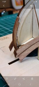
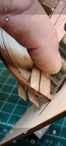
Started the planking to find that planks are larger than expected.

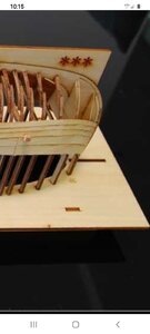
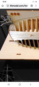
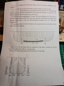
First I will paste a few screen shots from the Chinese forum and SC (kit developer) Facebook site.

Based on these pictures I am doing it correctly

Screenshot_20200809-101515_Chrome.jpgScreenshot_20200809-101552_Chrome.jpgScreenshot_20200809-101609_Chrome.jpgScreenshot_20200809-101325_Chrome.jpg

In the next posting my pictures.
 
Last edited:
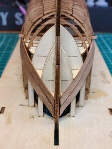
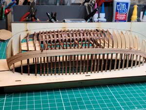
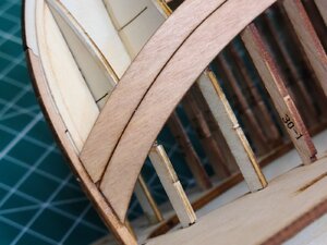
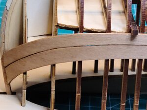
NOW SEE THE ISSUE ON THES PICTURES

View attachment 171860View attachment 171861View attachment 171862

At the bow they are larger than expected

I did some pencil mark at the place that "looks the correct ending".....

Do I try to slowly cut them to the correct length ?

What do you think ?

Thanks
Daniel

hi Daniel
I recommend that the third or last quarter of the boards and with you can more need to reduce their width so that it can be the hundredth to the state of the model in reality. I intend to apply a similar post that we do in the usual planking way. You may be required to stop and evaluate a situation where some of the boards can be disassembled in order to make the necessary adjustments. I believe and am sure that with the help of advice from other friends you will make the right decision and the result will turn out well for you
 
Thank you, but I do not see an ussue with the width. It is with the length.... they are too long.

I believe this is strange in a laser/cut/cumputer shaped planks. They all have diferente shapes and width. Could this happen with such technology ?

Unless I am misunderstanding your comments.

Thanks
Daniel
 
The reason the planks are different widths is so that they will ultimately take up all the space without the need for tapering. The downside of this is they must be precisely laid down (exactly like in the computer drawing) to the millimeter or you may end up with a gap. Even though I am a CAD/CNC/Laser guy I don't particularly care for pre-fabricated hull planking because it is nearly impossible for a human to build precisely to the drawing. I can already see very, very slight variances in the placement of your planks and you are only 2 strakes in. The overall "length" of your plank is not the primary concern - they are typically cut just a little bit long and need to be trimmed to fit into the rabbet - this is normal. Most likely your variances are appearing due to uneven fairing in of the frames/ribs. I notice most of them still have all the laser char. Ideally, all of the laser char would have been removed from the edges during the fairing in process..

Since it is a small model... the placement/positioning of these pre-fabricated planks becomes even more critical. In many ways, a larger model is easier to plank than a smaller one.

Hope this helps some.
 
Back
Top