Price is not an indicator of quality in these days.But in a 1000 pound kit where they are shown in the instructions Not Expected
I thinki can use the ones i havny use in mu AI Victory

-

SUBSCRIBE TO SHIPS IN SCALE TODAY!
The beloved Ships in Scale Magazine is back and charting a new course for 2026!
Discover new skills, new techniques, and new inspirations in every issue.
NOTE THAT OUR NEXT ISSUE WILL BE July/August 2026 -

Win a Free Custom Engraved Brass Coin!!!
As a way to introduce our brass coins to the community, we will raffle off a free coin during the month of August. Follow link ABOVE for instructions for entering.
- Home
- Forums
- Ships of Scale Group Builds and Projects
- Modelship Dockyard PoF HMS Enterprize 1774 - 1/48
You are using an out of date browser. It may not display this or other websites correctly.
You should upgrade or use an alternative browser.
You should upgrade or use an alternative browser.
Modelship Dockyard - New Kit H.M.S. Enterprize 1774 1:48 version by Modelship Dockyard
- Thread starter Modelship Dockyard
- Start date
- Watchers 65
- Joined
- Jul 24, 2016
- Messages
- 571
- Points
- 188

The quality of the kit is amazing its just so disappointing that important bits are not there
Yes agree, MD quality is fine. Have you noticed also that, there are no nails in set? Any nails for detailing, just strange for me.The quality of the kit is amazing its just so disappointing that important bits are not there
I must scratch them from diffrent sets.
- Joined
- Oct 14, 2020
- Messages
- 308
- Points
- 323

The making of these were planned to use the strips from the PE sheet. There were mentioning of this on page 70: "STEP 58 - WELL".while wating for bit of drying i am building the Fore Orlop Platform
Can find any doors or brass hinges surely these are included
Ive built the bulkheads
This is getting stupid
View attachment 552407
But yeah, as this page you shown is on a more previous page, this may do raise some confusion.
I have attached a image of the hinges on the pilot model, they were in a slightly different fasion by the idea of making it would be similar.

- Joined
- Oct 14, 2020
- Messages
- 308
- Points
- 323
I'm sorry for not including the nails in, the nails should be made by brass strips cut and inserted into the planks/parts. The kit have overall potentially over 10000 nails like this: https://drydockmodelsandparts.com/products/tiny-nails-0-3mm-200-bag, and including them would be hard.Yes agree, MD quality is fine. Have you noticed also that, there are no nails in set? Any nails for detailing, just strange for me.
I must scratch them from diffrent sets.
I cannot reveal here the cost for producing these nails, but they are sadly not cheap, so a good and affordable option is to use brass strips.
I understand, it's not a big problem, but it requires a lot of goid nails research.I'm sorry for not including the nails in, the nails should be made by brass strips cut and inserted into the planks/parts. The kit have overall potentially over 10000 nails like this: https://drydockmodelsandparts.com/products/tiny-nails-0-3mm-200-bag, and including them would be hard.
I cannot reveal here the cost for producing these nails, but they are sadly not cheap, so a good and affordable option is to use brass strips.
I was referring to nails used for details and fittings on model, such as capstan, knee, anchor arm.
- Joined
- Jul 24, 2016
- Messages
- 571
- Points
- 188
These would be fine But no instructions or diagramsThe making of these were planned to use the strips from the PE sheet. There were mentioning of this on page 70: "STEP 58 - WELL".
But yeah, as this page you shown is on a more previous page, this may do raise some confusion.
I have attached a image of the hinges on the pilot model, they were in a slightly different fasion by the idea of making it would be similar.
View attachment 553370
now devastated that the DEck Beams are NOT a shown in the Instructions which I downloaded and BOUGHT THE MODEL BECAUSE OF THE DETAIL
Blandford was great with three part sandwich but this model has nothing
If i had bought it in UK I would be demanding my money back
Attachments
- Joined
- Oct 14, 2020
- Messages
- 308
- Points
- 323
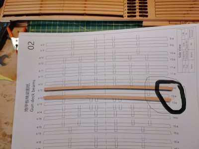
The reference of the deck beams were physical drawings instead of illustration on the instruction. The beams were indeed no longer sandwich style, we did this to make the beams looking more authentic. In beams were not in sandwich style in reality, and to make them that way would cause a clear separation look. We gathered feedback from the Blandford and early release version of the Enterprize in China, many reported that it was not a good style, so we have changed the fasion of the later version.These would be fine But no instructions or diagrams
now devastated that the DEck Beams are NOT a shown in the Instructions which I downloaded and BOUGHT THE MODEL BECAUSE OF THE DETAIL
Blandford was great with three part sandwich but this model has nothing
If i had bought it in UK I would be demanding my money back
The deck beams are not hard to make, there were physical drawings of the beams provided in the kit showing all the grooves and where they should be cut. Each beam have a reference, "a" for bow side and "b" for stern side, mark the grooves and cut them, then the beam is done.
Here I included a image from British National Maritime museum - https://www.rmg.co.uk/collections/objects/rmgc-object-67757
This type of beam could be achieved by using the current method we provided, but not the sandwich style we used to. Second image was the early pilot where we used the sandwich style.


- Joined
- Jul 24, 2016
- Messages
- 571
- Points
- 188
but that has sandwich - Its really the instructions that made me BUY the KIT
Not impressed with Zoltan critisising my building skills My first decent model sold at Sotherby's for 6000 pounds 40 years ago
Must admit I cant do so much now
Its difficult from the instructions to know exactly where to place the various deck parts So everything lines up later
Most of the KIT is Amazing like the frames
LOwer deck beams are great - why not do the same for the upper decks
Its just so disappointing that you have no explanation about the way it is built
I think on your next model you need to put explanations in like you have above
Ok - so removed the edge of D1/D2 and notched it its very easy
Liierally cut the sides of the slot and flicked out the bit between
THeb cleaned it up with a File
But getting the right position and depth would be useful
May i suggest that you mark the next model
It MUST be in the instructions so we know where we are going
When I built my Panart Victory 50 years ago the instruction where virtually non existant
And only Longridge book was available But i managed
![IMG_20251029_094642[1].jpg](https://shipsofscale.com/sosforums/data/attachments/537/537245-5d78e12054f9cb37493c6714f1c9789b.jpg?hash=S1_KdECzKE "IMG_20251029_094642[1].jpg")
Not impressed with Zoltan critisising my building skills My first decent model sold at Sotherby's for 6000 pounds 40 years ago
Must admit I cant do so much now
Its difficult from the instructions to know exactly where to place the various deck parts So everything lines up later
Most of the KIT is Amazing like the frames
LOwer deck beams are great - why not do the same for the upper decks
Its just so disappointing that you have no explanation about the way it is built
I think on your next model you need to put explanations in like you have above
Ok - so removed the edge of D1/D2 and notched it its very easy
Liierally cut the sides of the slot and flicked out the bit between
THeb cleaned it up with a File
But getting the right position and depth would be useful
May i suggest that you mark the next model
It MUST be in the instructions so we know where we are going
When I built my Panart Victory 50 years ago the instruction where virtually non existant
And only Longridge book was available But i managed
Last edited:
- Joined
- Jul 24, 2016
- Messages
- 571
- Points
- 188
so the hinges are not included - very confusing it should nut be in the instructions and at least mentioning not included that illustationThe making of these were planned to use the strips from the PE sheet. There were mentioning of this on page 70: "STEP 58 - WELL".
But yeah, as this page you shown is on a more previous page, this may do raise some confusion.
I have attached a image of the hinges on the pilot model, they were in a slightly different fasion by the idea of making it would be similar.
View attachment 553370
would be helpful
Last edited:

Are you writing about treenails or iron nails? If the latter, where would you use them?Have you noticed also that, there are no nails in set?
Allan
Iron nails. I ordered square small shoe nails for steps, knee arms, anchor arms, capstain itp and micro brass nails for attaching door hinges itp. Just small model detailing, in 1/48 its look amazing.Are you writing about treenails or iron nails? If the latter, where would you use them?
Allan
- Joined
- Jul 24, 2016
- Messages
- 571
- Points
- 188
but it should be explainedThe reference of the deck beams were physical drawings instead of illustration on the instruction. The beams were indeed no longer sandwich style, we did this to make the beams looking more authentic. In beams were not in sandwich style in reality, and to make them that way would cause a clear separation look. We gathered feedback from the Blandford and early release version of the Enterprize in China, many reported that it was not a good style, so we have changed the fasion of the later version.
The deck beams are not hard to make, there were physical drawings of the beams provided in the kit showing all the grooves and where they should be cut. Each beam have a reference, "a" for bow side and "b" for stern side, mark the grooves and cut them, then the beam is done.
Here I included a image from British National Maritime museum - https://www.rmg.co.uk/collections/objects/rmgc-object-67757
This type of beam could be achieved by using the current method we provided, but not the sandwich style we used to. Second image was the early pilot where we used the sandwich style.
View attachment 553435
View attachment 553436
Just what you said above
If youve not had to do it before Its not obvious
- Joined
- Jul 24, 2016
- Messages
- 571
- Points
- 188
if you want tree nails i use small thin square stripsAre you writing about treenails or iron nails? If the latter, where would you use them?
Allan
I pull it through an old tobacco tin from 50 tears ago 7 or 8 different sizes of holes an pull the wood through successive smaller holes
Will try and fid it - i do need it!!
- Joined
- Jul 24, 2016
- Messages
- 571
- Points
- 188
REally Confusing D1 and D2 are 1 LOWER deck
D3 and D4 anre different DEck GUN DECK
Which explains why they are different at ends
Toook me some time to work oit as the first illustation of how they are built id GN DEck
THink ki am ok now!!
![IMG_20251029_105825[1].jpg](https://shipsofscale.com/sosforums/data/attachments/537/537247-5f41e5317f04f49f399ef84896cd4e06.jpg?hash=Io6705dcST "IMG_20251029_105825[1].jpg")
D3 and D4 anre different DEck GUN DECK
Which explains why they are different at ends
Toook me some time to work oit as the first illustation of how they are built id GN DEck
THink ki am ok now!!
Attachments
Last edited:
Interesting solution and I am guessing they would look great. Hope you post some photos when you get them. I have always just gone with copper wire and made nails as I can use these as is, then once in place and wiped clean with some water to get the filings removed, blacken in place with diluted liver of sulfur as it will not stain the wood. I cannot find any contemporary drawings that show square heads so only used round stock, but would love to see drawings that show the square nails.Iron nails. I ordered square small shoe nails for steps, knee arms, anchor arms, capstain itp and micro brass nails
Allan
Sounds like a nice home made draw plate! I just use a regular draw plate with holes down to 0.016" diameter and my own choice of wood at these small diameters has been bamboo most of the time. Bamboo from skewers at found at the grocery store works really well and the color is very subtle. I slit them to a suitable size then start drawing them as you describe going from the larger holes to the smallest required.if you want tree nails i use small thin square strips
I pull it through an old tobacco tin from 50 tears ago 7 or 8 different sizes of holes an pull the wood through successive smaller holes
Allan


Getting the notches cut in the exact right place before the beams are installed is difficult regarding alignment if the beams are not perfectly placed. Many find it better to install the beams, then mark out the notches for the carlings and cut or file a notch so they are properly aligned. Just another way to achieve a perfect result. It is not such a big deal for a cross section model as there are not that many beams and it is pretty much straight line midships, but for a full hull, it can be tricky to have everything lined up.now ive got over the notches not being cut out
Allan
@shota70 took a very interesting approach to this detail and start modeled these nails.Interesting solution and I am guessing they would look great. Hope you post some photos when you get them. I have always just gone with copper wire and made nails as I can use these as is, then once in place and wiped clean with some water to get the filings removed, blacken in place with diluted liver of sulfur as it will not stain the wood. I cannot find any contemporary drawings that show square heads so only used round stock, but would love to see drawings that show the square nails.
Allan
I also want to use it in my MD constructions.
POF L'Amarante Corvette de 12 canons 1744 1:36 (Ancre Monograph- Gérard Delacroix) By Shota
Hey Shota, what else can I say that the other colleagues have already said? Wonderful, breathtakingly beautiful, simply world class? Yes, you're right, I can say it ... Simply marvellous ... Keep it up ... I'm a big fan of your boat and the way you build it. Thumbsup :D
shipsofscale.com
Looking for where to purchase tiny nails with a round head with a square-pointed end?
Hello my dear friends I am asking for your help in locating an online store where you can purchase tiny nails with a round head along with a square or pentagonal end. I am not looking for a round head alone or a square or pentagonal head alone, but a head that combines both shapes together. I...
shipsofscale.com
It would seem (so my research has concluded) that square nails were indeed a part of French ship construction. Perhaps it was used by other nations as well. With that said, proceed with caution on an English ship, my friend ") .
.
Of course, you are the captain and should do what appeals to your eye and brings your model to the look you want! My work is replete with all manner of departures, and no one has ever complained (well, that's not true...I just try to not let it bother me too much ).
).
.Of course, you are the captain and should do what appeals to your eye and brings your model to the look you want! My work is replete with all manner of departures, and no one has ever complained (well, that's not true...I just try to not let it bother me too much
).