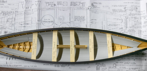
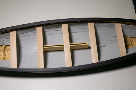
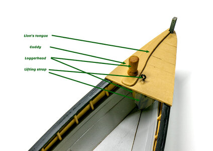
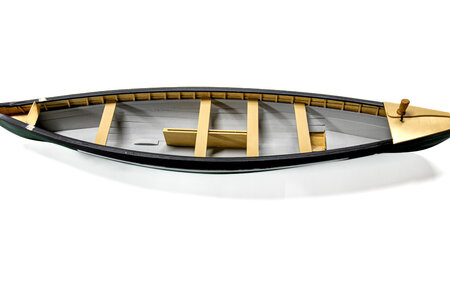
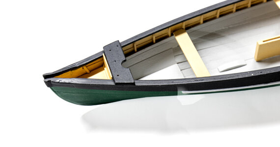
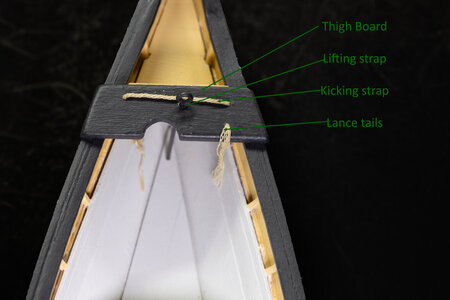
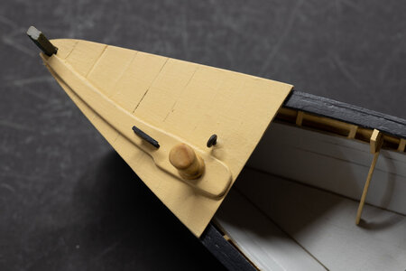
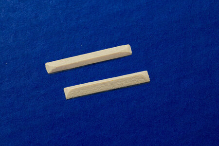
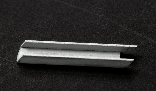
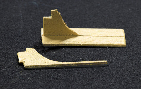
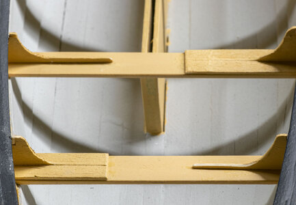
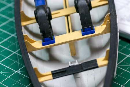
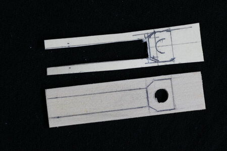
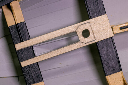
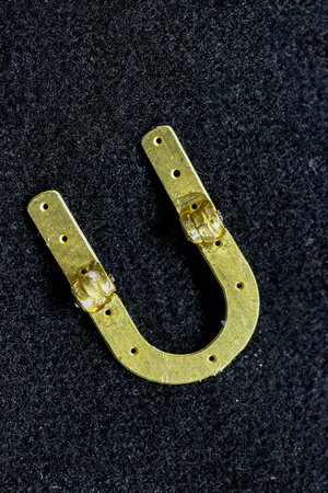
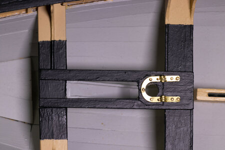
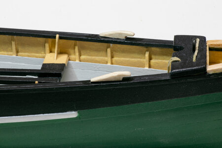
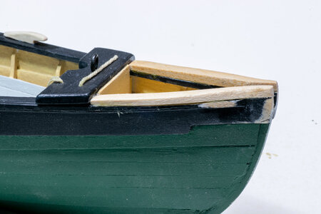
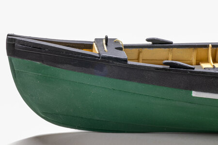
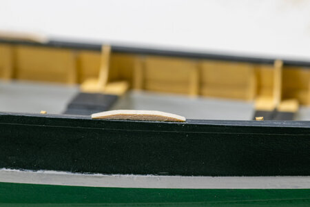
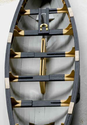
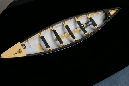
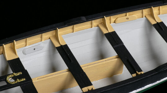
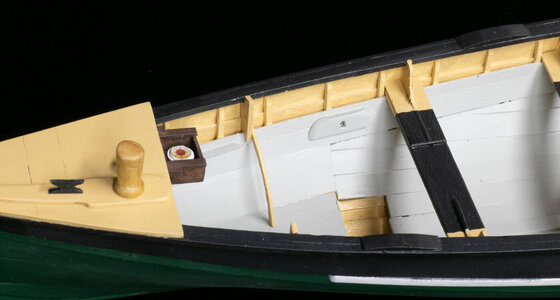
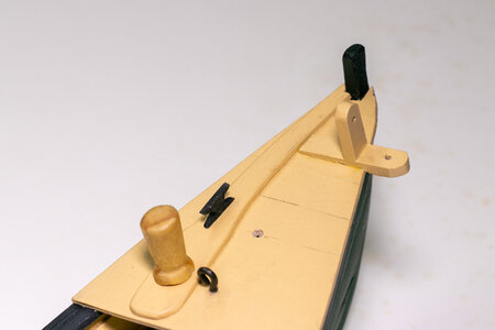
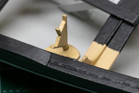
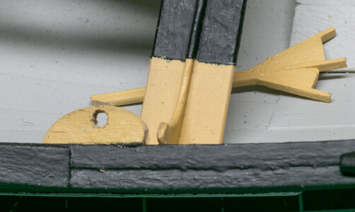
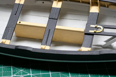
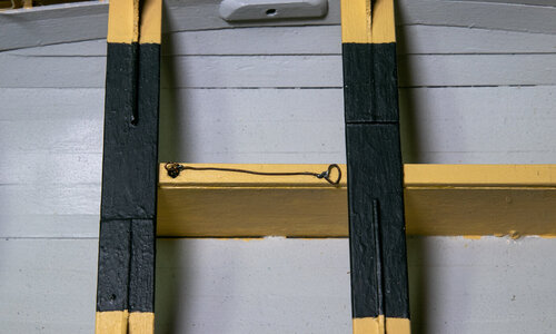
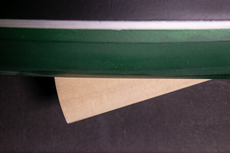
Oar chocks are installed. These parts are used to hold the ends/handles of the oars when the oars are in the oarlocks but not being used. Different heights are required due to equipment or design of the boat. For instance, the one above the thwart riser is there as it has to go over the top of one of the rope tubs that will be placed in the boat later. The other high one is for the bow oar that needs to go over the mast tabernacle.
View attachment 340628
I found a picture of a compass rose online and printed it at an appropriate size. This was glued to the metal compass bowl that is supplied with the kit. The compass drawer is made from stock pieces of boxwood stained and glued in place. The builder has the choice of mounting under the stroke thwart or the cuddy.
View attachment 340629
I chose to make the steering oar brace as per John Fleming's method. Holes were drilled for the rope that holds the oar in place and for the line from the stern that passes into the cuddy area.
View attachment 340630
The harpoon crotch and its chock are constructed as per the MS instructions and plans. The chock is glued to the gunnel and crotch is removable. I still need to add a safety line to keep it from falling out of the boat when not in place.
View attachment 340632View attachment 340633
The top of the centerboard case was constructed after the centerboard is fitted into the case. There is a pin in the lower right corner that holds the centerboard in place. The eye for mounting the handle for raising and lowering the centerboard is seen through the hole in the cover. In other pictures the upper half of the metal strap for lifting/lowering the centerboard is visible and the centerboard in the lowered position (which is how I am going to display the model) is seen. I am still considering whether I will rebuild the metal centerboard strap or not.
View attachment 340634View attachment 340635View attachment 340636
