• LUCZORAMA SHIPWRECK SCAVENGER HUNT GIVEAWAY. 4 Weeks of Fun • 1 Legendary Prize ((OcCre’s Fram Ship)) • Global Crew Welcome!
    **VIEW THREAD HERE**

NHI Kolibri N-3, scale 1:48, scratch build

Finally I convinced myself to seriously work on that thrice darned tank suspension fittings.
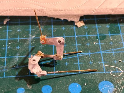
Initially my efforts were aimed at replicating the original suspension. I used some brass sheet, t=0,25mm and started playing around with some ideas I had.
Both the undercarriage cross spars and the bolts of the tank suspension are parallel to one another. To add to the difficulties the fittings should preferably measure 6mm by 2mm.
After some trial and error I came to adopt a producible solution, instead of lifelike representation.
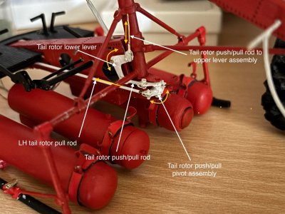
The pictures below show both the front- and rear suspension of the tanks on a dry fit of two of the four tanks.
Now I have to let it sink in and see whether or not I still like this solution after looking at it for a few days.

General view:
View attachment 523948

Front suspension detail:
View attachment 523949

Rear suspension detail:
View attachment 523950

Early prototype front suspension:
View attachment 523953

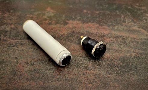
Als some work was done on the LH & RH nav lights.
I used 2mm transparent acryl tube, dia 2mm and inserted an SMD, used some CA to fix the SMD and applied some paint:

The current mess of the center tanks with the necessary wiring:
View attachment 523951

Just to make sure the lights work:
View attachment 523952

Still a lot of issues to solve before I can declare success…
Also, despite having gone from 1:48 to 1:16, even the larger scale doesn’t mean that all parts become easy to make.
Good to see a very nice update of the build, Johan. And as I wrote: The size of the scale is inversely proportional to the details of the parts. The bigger the scale, the more you can deep into the details. But you doing your research and find solution for the Kolibri.
Regards, Peter
 
Finally I convinced myself to seriously work on that thrice darned tank suspension fittings.
Initially my efforts were aimed at replicating the original suspension. I used some brass sheet, t=0,25mm and started playing around with some ideas I had.
Both the undercarriage cross spars and the bolts of the tank suspension are parallel to one another. To add to the difficulties the fittings should preferably measure 6mm by 2mm.
After some trial and error I came to adopt a producible solution, instead of lifelike representation.
The pictures below show both the front- and rear suspension of the tanks on a dry fit of two of the four tanks.
Now I have to let it sink in and see whether or not I still like this solution after looking at it for a few days.

General view:
View attachment 523948

Front suspension detail:
View attachment 523949

Rear suspension detail:
View attachment 523950

Early prototype front suspension:
View attachment 523953

Als some work was done on the LH & RH nav lights.
I used 2mm transparent acryl tube, dia 2mm and inserted an SMD, used some CA to fix the SMD and applied some paint:

The current mess of the center tanks with the necessary wiring:
View attachment 523951

Just to make sure the lights work:
View attachment 523952

Still a lot of issues to solve before I can declare success…
Also, despite having gone from 1:48 to 1:16, even the larger scale doesn’t mean that all parts become easy to make.
I think that works well, just add a band or strap on the back and it will be close enough. And you could even add two triangles on each side of the eye shaft that join the strap. ;)
 
Finally I convinced myself to seriously work on that thrice darned tank suspension fittings.
Initially my efforts were aimed at replicating the original suspension. I used some brass sheet, t=0,25mm and started playing around with some ideas I had.
Both the undercarriage cross spars and the bolts of the tank suspension are parallel to one another. To add to the difficulties the fittings should preferably measure 6mm by 2mm.
After some trial and error I came to adopt a producible solution, instead of lifelike representation.
The pictures below show both the front- and rear suspension of the tanks on a dry fit of two of the four tanks.
Now I have to let it sink in and see whether or not I still like this solution after looking at it for a few days.

General view:
View attachment 523948

Front suspension detail:
View attachment 523949

Rear suspension detail:
View attachment 523950

Early prototype front suspension:
View attachment 523953

Als some work was done on the LH & RH nav lights.
I used 2mm transparent acryl tube, dia 2mm and inserted an SMD, used some CA to fix the SMD and applied some paint:

The current mess of the center tanks with the necessary wiring:
View attachment 523951

Just to make sure the lights work:
View attachment 523952

Still a lot of issues to solve before I can declare success…
Also, despite having gone from 1:48 to 1:16, even the larger scale doesn’t mean that all parts become easy to make.
Your skill at manufacturing small brass pieces is amazing.
 
Good to see a very nice update of the build, Johan. And as I wrote: The size of the scale is inversely proportional to the details of the parts. The bigger the scale, the more you can deep into the details. But you doing your research and find solution for the Kolibri.
Regards, Peter
Thanks, Peter, she's still a very interesting and challenging project.
 
I think that works well, just add a band or strap on the back and it will be close enough. And you could even add two triangles on each side of the eye shaft that join the strap. ;)
That's food for thought. I'll look into that, see if I vpcan obtain a more realistic look.
Thanks for the tip!
 
Very interesting attachment hardware in your design Johan. The aft end of the tanks appears to be able to swing ever so slightly on a hinge point. The overall detail is outstanding.
Thanks Dan, keen eyes for details you still have!
The fwd attachment of the tanks is a straight forward hinge point, whereas the aft attachment is a link, allowing fwd and aft movement. I tried to get this in scale 1:16, but even with pins of 0,5mm (plus subsequent bushings of at least 1,0mm) it leaves no room for a swivel link, so I had to cheat...
 
Your skill at manufacturing small brass pieces is amazing.
Ha Ted, thanks so much for your compliments.
I'll not start about the difficulties in order to try and get those details done. One things for sure, I really miss out on some nice miniature machining capability.
 
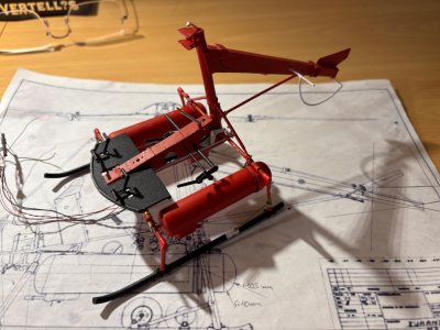
Although at a snails pace, work on this nimble helicopter continues.
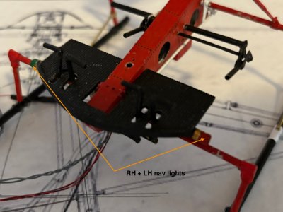
I added the two LH- and RH nav lights, see picture below. I used clear acrylic tube for the housing of the lights and brass tube for the lamp fitting. The housing of the lights are painted in the appropriate colors.
The routing of the wires is also coming together: the wires will run below the floor towards he RH center tank, which also houses the light switch. There is unfortunately very little space to a) connect the wires and b) stow the surplus wires in the RH center fuel tank. Still something to pay attention to.

IMG_1021.jpeg
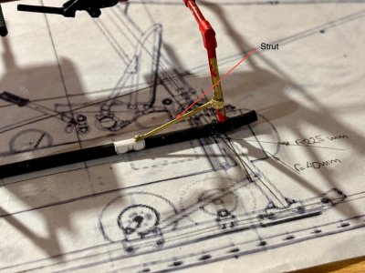
Another tiny detail which still needed to be added were the struts, connecting the skids to the aft cross beam legs. Additional detailing is still required for the wheels attachment, also a lot of touch up is needed...Sick

IMG_1019.jpeg

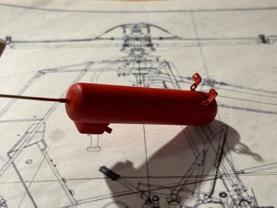
Finally, after dragging my feet for months on end, I could no longer avoid to try and use the airbrush. @Peter Voogt gifted me an airbrush, minus compressor, and after buying a low cost compressor, I postponed any activities concerning using the airbrush for as long as I could. Now getting close to the point where I have to install the fuel tanks I had to start learn ng to use the airbrush.

Below two pictures of one of the fuel tanks after two layers of paint. Not perfect, but I think it's close enough for an airbrush rookie:

IMG_1018.jpegIMG_1017.jpeg
 
Back
Top