-

Win a Free Custom Engraved Brass Coin!!!
As a way to introduce our brass coins to the community, we will raffle off a free coin during the month of August. Follow link ABOVE for instructions for entering.
-

PRE-ORDER SHIPS IN SCALE TODAY!
The beloved Ships in Scale Magazine is back and charting a new course for 2026!
Discover new skills, new techniques, and new inspirations in every issue.
NOTE THAT OUR FIRST ISSUE WILL BE JAN/FEB 2026
- Home
- Forums
- Ships of Scale Group Builds and Projects
- Group Build Archives
- Blandford Cross Section PoF Group Build
You are using an out of date browser. It may not display this or other websites correctly.
You should upgrade or use an alternative browser.
You should upgrade or use an alternative browser.
Kurt Konrath
Kurt Konrath
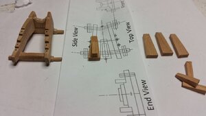
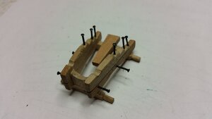
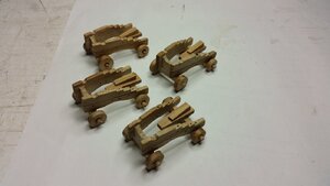
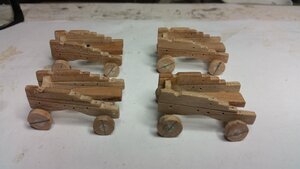
Good work on the gun carriages, I will be watching to see how they look when done and rigged to hull.
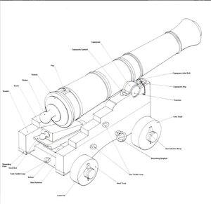
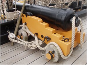
Hello Knut. That's me again, your buddy Jim. By now, you should be already adjusted to my comments, and I really hope you don't mind them. So what's the deal? I am lucky to find a really great picture (with all parts labeled) of an example of the English canon. I don't think this cannon belongs to a specific ship, but it definitely shows some English style (IMHO), and a great way to learn. So...the first photo shows the axletree ready to accept Linch Pin, what happened to the axletree in the last pictures?? They are flush both with Hind fore trucks  I think, with this scale, you can show Linch Pin and even Iron axletree hoop. Come on Man, I know you are capable do it!!!!


Last edited:
In this case I would recommend Chinese ink. I is really cheap an results are wonderfulA little more equipment to test before the bonding of the frames begins.
Drawing plate - 30 days from order until it arrived in the mail, twice as expensive due to customs and fees. is not available for sale in norway.
View attachment 82274
Blackboard paint that gets the appearance of ebony with a top layer of wood oil. I hope.
View attachment 82276View attachment 82275
Dave's needlework technique for nails.
View attachment 82277
Thin black board for spacer deck planks, needles for glue applicator, black ink to make black glue.
View attachment 82278
White wood glue and black ink to make black glue.
View attachment 82279View attachment 82280
I know that old boat builders used tar between all parts when they mounted frames, I want to try with black glue.
And it's just trying.
- Joined
- Dec 3, 2018
- Messages
- 2,451
- Points
- 538

@ Schrader - Chinese ink will be used for later black color needs, thanks for the tip-
@Jimsky - sorry for responding so late, I haven't had much time left over lately.
Very good and informative pictures and drawing, yes, I will do these imitations as you say.
It will certainly be some fiddely work, but it will get a much better look in the end. thanks-
Regards-
@Jimsky - sorry for responding so late, I haven't had much time left over lately.
Very good and informative pictures and drawing, yes, I will do these imitations as you say.
It will certainly be some fiddely work, but it will get a much better look in the end. thanks-
Regards-
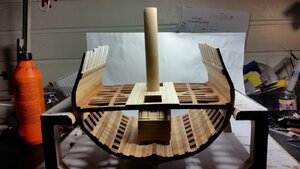
Hi Knut! It may be a photo distortion, but the mast diameter looks to be too large. Did you use 1” as per the plans? Here is a part of a discussion I had with Mike about the mast diameter. 9/16” is correct, not 1”.
Hey Mike!
I didn't want to clutter up the general thread with this question, but there appears to be a discrepancy in the drawings for the mast diameter in 1:32 scale. In the detail drawing of the mast (on the mast and main deck beams sheet) the mast itself has a diameter of 1". There is some narrowing below the main deck, but that portion on the mast visible above the main deck is 1" in diameter. In scale that would be 2ft. 8 in. in diameter. The longitudinal drawings of hull, as well as the plan views of the deck framing (where the holes are for the mast to pass through the decks) make the mast 9/16" in diameter , or 1'-6" in real life. That is pretty close to the 1' 8-1/2" diameter listed in the AOTS book on Blandford. It appears that the 9/16" diameter is correct. The mast would be way too thick at 1". Also, is it necessary to bring the diameter of the mast down below the main deck? The most simple approach would be to take a 9/16" dowel, form a 3/8" tenon on the end for the mast step, drill a 3/8 " hole (mortise) in the step for the tenon and call it done! Am I wrong?
In your 1/1/18 revision of the 1:48 scale plans, the mast diameter is 3/8", which would be 9/16" at 1/32 scale.
Kurt Konrath
Kurt Konrath
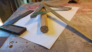
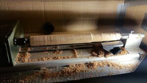
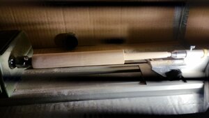
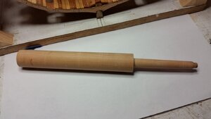
Great lathe work on the mast creation.
Hi Knut! It may be a photo distortion, but the mast diameter looks to be too large. Did you use 1” as per the plans? Here is a part of a discussion I had with Mike about the mast diameter. 9/16” is correct, not 1”.
Hey Mike!
I didn't want to clutter up the general thread with this question, but there appears to be a discrepancy in the drawings for the mast diameter in 1:32 scale. In the detail drawing of the mast (on the mast and main deck beams sheet) the mast itself has a diameter of 1". There is some narrowing below the main deck, but that portion on the mast visible above the main deck is 1" in diameter. In scale that would be 2ft. 8 in. in diameter. The longitudinal drawings of hull, as well as the plan views of the deck framing (where the holes are for the mast to pass through the decks) make the mast 9/16" in diameter , or 1'-6" in real life. That is pretty close to the 1' 8-1/2" diameter listed in the AOTS book on Blandford. It appears that the 9/16" diameter is correct. The mast would be way too thick at 1". Also, is it necessary to bring the diameter of the mast down below the main deck? The most simple approach would be to take a 9/16" dowel, form a 3/8" tenon on the end for the mast step, drill a 3/8 " hole (mortise) in the step for the tenon and call it done! Am I wrong?
In your 1/1/18 revision of the 1:48 scale plans, the mast diameter is 3/8", which would be 9/16" at 1/32 scale.
5/8" diameter main mast at the deck level would be fine. 13/16" or 1" is too wide.
From AOTS:

- Joined
- Dec 3, 2018
- Messages
- 2,451
- Points
- 538

Dave you're right, the mast is way too thick.
I show some pictures of my drawings, scale is similar on all, why is there are different thicknesses in several of the drawings.
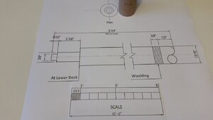
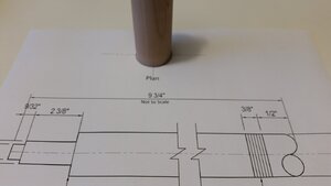
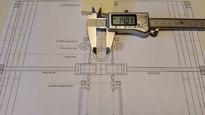
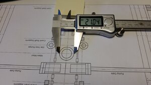
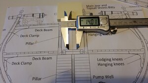
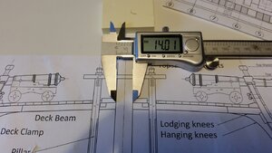
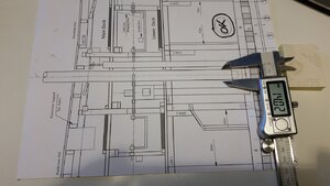
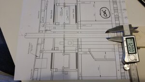
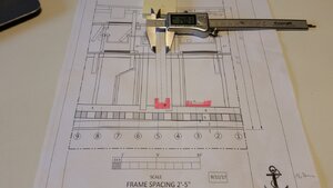
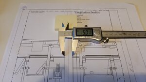
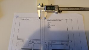
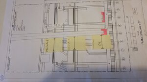
I can fix this error by turning the thickness of the mast down and make the mast rings the same thickness as the mast is now.
Hope you see the problems I have with drawings, but, this can be fixed, I think.
The first two pictures are of the drawing I made the mast after, the lower deck plan had the same thickness of the mast.
..
.
I show some pictures of my drawings, scale is similar on all, why is there are different thicknesses in several of the drawings.


I can fix this error by turning the thickness of the mast down and make the mast rings the same thickness as the mast is now.
Hope you see the problems I have with drawings, but, this can be fixed, I think.
The first two pictures are of the drawing I made the mast after, the lower deck plan had the same thickness of the mast.
..
.
- Joined
- Dec 3, 2018
- Messages
- 2,451
- Points
- 538

Oops, I forgot to ask, the mast should be the same thickness from the lower deck to the top.
And what is the thickness in mm, sorry, but I have not been able to learn, mm / insh, calculator, as Dave has shown me before.
I feel really stupid, wrong with many drawings that I was sure of right.
But, I'm going to clear and cheat this model so it looks reasonably good.
I haven't given up, but, it's just before.
..
Hi Knut!
I was able to catch the error before I made the mast...but I know you can fix it!!
I left the mast one diameter, except for the round tenon on the foot that sits in the mast step. Most of the mast below deck is hidden by the well and the chain pump apparatus.
According to the AOTS book on Blandford, the main mast was 1' 8-1/2" or 20.5" in diameter. or 15.875 mm!
This is what I use! The icon is on my desktop!
 www.rapidtables.com
mm to inches | millimeters to inches converter
mm to inches (in) converter and how to convert.
- Joined
- Dec 3, 2018
- Messages
- 2,451
- Points
- 538

Dave, thank you for the answer / goal, after this I think I will fix the rest of the work whith measuring directly from the drawings and with caliber.
PoulID, If you look at the pictures, there are three for different thicknesses of the mast on the drawings.
The caliber shows Insh / mm, but not, EX-1 '8-1 / 2 "or 20.5", this confuses.
Most of the work goes well with the help of patterns and measurements directly from the drawings.
Thanks again for your help with this issue.
My second project (Rattlesnake), will be something completely different, as I'm sure all the drawings are on the same scale.
Knut-
..
- Joined
- Dec 3, 2018
- Messages
- 2,451
- Points
- 538

@ DST07, thank you for your interest, this is my first build of this type, if you want to start yourself then I recommend you to look through the logs of the other builders in this group, there are many others who have not done so many mistakes like me, good luck, greetings-
- Joined
- Dec 3, 2018
- Messages
- 2,451
- Points
- 538

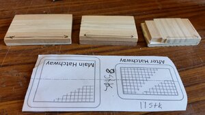
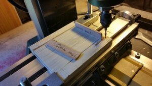
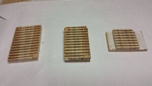
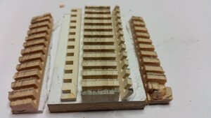
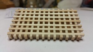
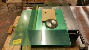
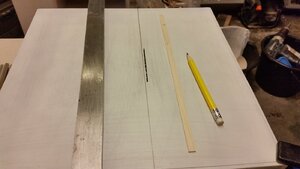
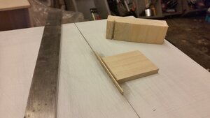
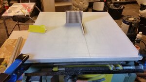
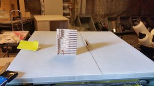
Experiment with FET.
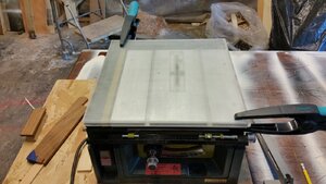
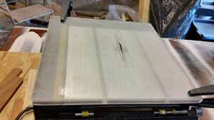
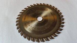
Here I have made a jig with an acrylic plate, the guide board has the same thickness as the saw blade, 1.7mm.
Due to the wrong saw blade with teeth that are a little thicker than the blade itself,
VERY BAD RESULT.
Well, another lesson, result, buy saw blades that are completely flat .
Greeting-
Here I have made a jig with an acrylic plate, the guide board has the same thickness as the saw blade, 1.7mm.
Due to the wrong saw blade with teeth that are a little thicker than the blade itself,
VERY BAD RESULT.
Well, another lesson, result, buy saw blades that are completely flat .


Greeting-

