Oseberg - Ver. 3 - Pavel Nikitin - 1:25

Following up on my order to Pen and Sword for The Oseberg Ship, I received an "invoice" today stating that due to insufficient quantities, the book had been backordered. :oops:

When I ordered it, the web site said it was available. Then sent me an order confirmation. They charged my credit card. I don't know if things work differently in the UK, but around here, unless you are knowingly placing a backorder or special order, your card is not charged if the item is not in stock and usually, for backorders, it is not charged until the product ships.

I sent them an email asking if they are expecting an imminent shipment of the books, and if not, how long they plan on holding on to my money. Sigh.
I received an invoice from them today as well, and they charged my credit card too. When I ordered from them it was listed as available, this is the message I got on my invoice...

1 backorders recorded
There is insufficient inventory to supply this product Temporarily Out of Stock

They gave no mention as to when/if it will be back in stock. It does say on the top of the invoice, payment terms 30 days. I can only hope they'll refund my money if it's not back in stock by then. Disappointing to say the least, frustrating is more like it.

Steve
 
Breaking news! This just in ...

I wrote earlier that I had emailed Dr. Vibeke Bischoff, author of The Oseberg ship, Reconstruction of form and function seeking permission to post illustrations from the book. She did reply, and the bad news is that The Viking Museum (co-publisher of the book) declined to give their permission. :(


Wait for it ...


The book is actually the published version of her doctoral dissertation. I already knew this, but probably failed to mention it here. The good news is that Dr. Bischoff very graciously provided a link to her dissertation and gave her permission for me to share it here! The work is in two parts - the first being mostly text (in Danish) with many supporting photos and illustrations, and the second part is all drawings and illustrations. for example, I was asked earlier which rooms contained deck boards that weren't fastened down. That can be seen in blue in Part 1, page 128. This work contains most, if not all the illustrations used in the book as well as some I didn't recognize (just upon my first skim of the works.)

Dr Vibeke Bischoff's dissertation:
Reconstruction of the Oseberg Ship: Form, Construction and Function


The documents are in PDF format, so you can download them and view them in your favorite PDF viewer (I prefer Sumatra over Adobe). If you view them online, you can highlight passages, right-click and select translate to read it in English (at least in Chrome - if you use a different browser, your mileage may vary.)

Dr. Bischoff also mentioned that while the book is available at the museum, they have stopped shipping it due to the amount of work it takes. She then referred me to Pen and Sword. When I bemoaned the difficulties that Steve and I (and perhaps others) are having with them, she said the museum had about 1000 copies and that she would love for them to find a good home, so she is going to try to light a fire under them and see if they can replenish Pen and Sword's inventories.

Dr. Bischoff's email is available here in case anyone wishes to thank her personally.

In the immortal words of Walter Cronkite, "And that's the way it is..."
 
Last edited:
I just heard from Joanne at Pen and Sword. She said they had at least 10 backorders from people waiting for the book and that the museum is notoriously slow in shipping. Hopefully, Dr Bischoff can get the ball rolling.
 
I just heard from Joanne at Pen and Sword. She said they had at least 10 backorders from people waiting for the book and that the museum is notoriously slow in shipping. Hopefully, Dr Bischoff can get the ball rolling.
Excellent news Russ. I re-ordered the book yesterday and am on their back order list. One would think if they have a 1000 copies sitting there they could use the funds for the new museum. I even tried to buy a Norwegian version from Dr Bischoff last year but no dice.
 
Breaking news! This just in ...

I wrote earlier that I had emailed Dr. Vibeke Bischoff, author of The Oseberg ship, Reconstruction of form and function seeking permission to post illustrations from the book. She did reply, and the bad news is that The Viking Museum (co-publisher of the book) declined to give their permission. :(


Wait for it ...


The book is actually the published version of her doctoral dissertation. I already knew this, but probably failed to mention it here. The good news is that Dr. Bischoff very graciously provided a link to her dissertation and gave her permission for me to share it here! The work is in two parts - the first being mostly text (in Danish) with many supporting photos and illustrations, and the second part is all drawings and illustrations. for example, I was asked earlier which rooms contained deck boards that weren't fastened down. That can be seen in blue in Part 1, page 128. This work contains most, if not all the illustrations used in the book as well as some I didn't recognize (just upon my first skim of the works.)

Dr Vibeke Bischoff's dissertation:
Reconstruction of the Oseberg Ship: Form, Construction and Function


The documents are in PDF format, so you can download them and view them in your favorite PDF viewer (I prefer Sumatra over Adobe). If you view them online, you can highlight passages, right-click and select translate to read it in English (at least in Chrome - if you use a different browser, your mileage may vary.)

Dr. Bischoff also mentioned that while the book is available at the museum, they have stopped shipping it due to the amount of work it takes. She then referred me to Pen and Sword. When I bemoaned the difficulties that Steve and I (and perhaps others) are having with them, she said the museum had about 1000 copies and that she would love for them to find a good home, so she is going to try to light a fire under them and see if they can replenish Pen and Sword's inventories.

Dr. Bischoff's email is available here in case anyone wishes to thank her personally.

In the immortal words of Walter Cronkite, "And that's the way it is..."
Hi Russ, thanks for the link...that's awesome.

I appreciate your diligence in finding and getting permission to post Dr. Vibeke Bischoff's dissertation. Hopefully the museum will get off their rear ends and ship the books needed to Pen and Sword quickly, I can see no reason for them to just sit on them.

Thanks again,
Steve
 
Deck boards (cont'd)

Work continues on preparing the deck boards. Boy, there's a lot of them!

The first step was to get all the "rooms" worth of boards separated, the long edges sanded, pushed together and taped so I could sand the short edges to fit between the bitis. I thought it would be pretty straight forward, but there were a couple of snags I should mention. I put the first room #1 together (the one that I moved forward and turned the ends around) and fit it to the boat, but it came out a little bit short. Oh no, what did I do wrong?

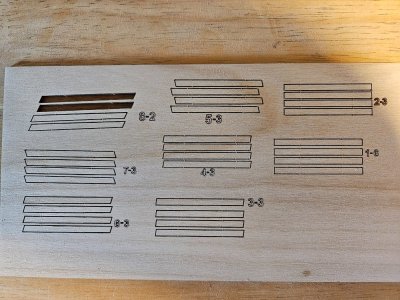
Well, my first mistake was not watching the next installment of Pavel's video. After watching, I had an "a-ha" moment. There's a sheet of parts - little strips - that go right at the ends of each row of boards. This is not documented anywhere in the instructions. Sigh. Moral: WATCH THE VIDEOS!
This is the sheet:

20250330_143458.jpg

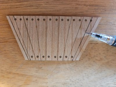
Next I did a row #2, based on the sheet numbers on the instructions and it wasn't even close! I started measuring the parts (there are a few single boards and one with 2 boards that isn't marked) and I couldn't make it work out, so I decided to save those until last. Rows 3 -7 went pretty smoothly. Rows 8 needed some work. They came out significantly too wide, but not by the same amount at the narrow and wide ends of the set. So, I measured the width of each edge of the set, then along the ledges where they sit, subtracted and split the difference. I removed the excess from the first full width board, leaving the edge strips intact.

20250330_143525.jpg

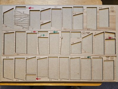
Now, those two row #2 sets. I kept the groups taped together as they popped out of the sprues and then I felt like I was playing with one of those sliding tile puzzles as I shifted pieces around until I found a combination that produced two sets of the same length and that actually fit properly in the boat. Pavel's drawings are confusing at best and I believe the numbering is off. Below are the combinations that worked for me. Notice that one group of two boards is not even marked. The sets marked in red make one row and the green ones make the other.

20250402_180117.jpg

I have not yet done rooms #9, as I'm still undecided as to whether I'm keeping them as provided or matching the original ship more. You can see the difference in Dr. Bischoff's dissertation, part 2, page 57.

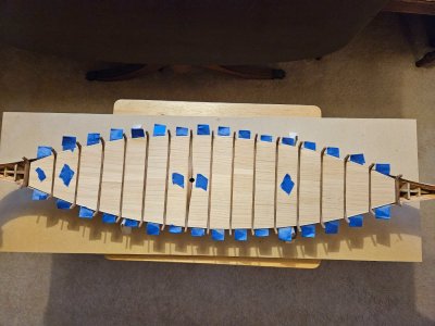
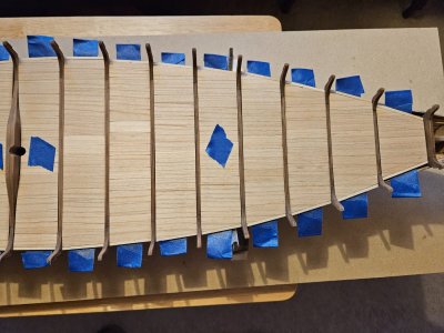
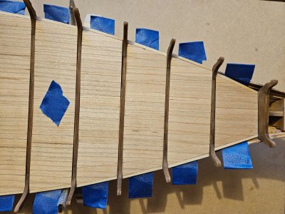
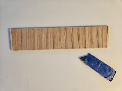
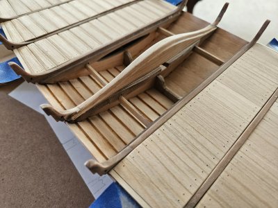
So here's where I am so far. The rooms with the blue tape in the middle are those that don't get treenails if you desire to match the original. Left is forward, right is aft.

20250402_182129.jpg

20250402_182137.jpg

20250402_182142.jpg

20250402_182204.jpg

On to the drilling...
 
Deck boards (cont'd)

Work continues on the deck boards - this is going to take a while.

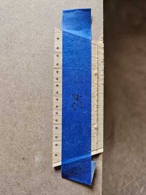
The next step was drilling treenail holes. I had the opportunity to use my new toy - the Arrowmax drill. I mounted it on a piece of plywood to make a larger table. I found that even with a fence, there is just enough play in the spindle assembly that the drill bit tended to wander slightly. Plus, the unit would bind when using the handle to lower the spindle (maybe a bit of wax on the rails would help that), so I had to use a different grip on the spindle to minimize bit wandering and keep it from binding. Once I figured out a good method, drilling went fine. Despite the shortcomings of the drill press frame, I still think the Arrowmax will shine when handheld like a pencil for tight locations. I think it would beat a pin vise, especially with the number of rivet holes in the strakes (yet to come).

20250405_105651.jpg

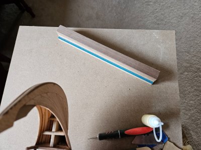
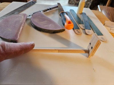
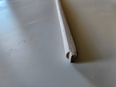
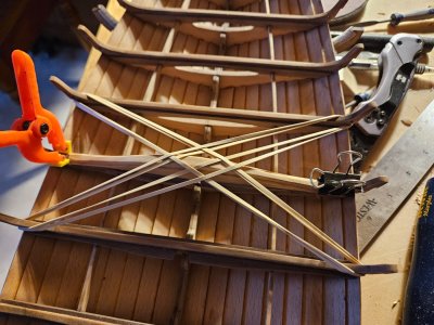
Once all the holes were drilled, the next step was to get the deck boards sitting at the same level with respect to the bitis. Pavel shows doing this in his videos. There is no standard amount to remove, so each set requires repeated test fittings as you sand. Five minutes on a table saw with a piece of scrap created a sanding block that does the trick rather quickly.

20250409_180130.jpg

20250409_180218.jpg

20250409_180300.jpg

To be continued...
 
Mast

@JBB , this one's for you! ;)

Our 14 mo. old great grandson came for a sleepover Friday night - yay! I thought I would take a break from deck boards and do something quick and easy while he napped. (To be honest, though, he's just started walking and after chasing that little rascal around all morning, we're the ones who needed a nap! o_OSleep ROTF)

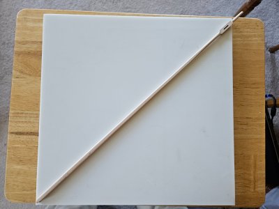
I decided to tackle the mast. It's provide in two pieces because the full length mast wouldn't fit into the box. It's a twice-lasered piece to allow tapering in both dimensions.

20250412_104010.jpg

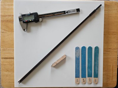
First step was to clean up all the char so I could see pencil marks on it.

20250412_112008.jpg

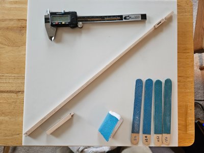
Next get a good fit for the mortise and tenon on the extension and glue it in place.

20250412_140639.jpg

According to Dr. Bischoff, the remains of the mast found in the Oseberg (the lower third or so) had a cylindrical cross section except for the forward face which was flat. The mast likely started out as a square beam, was made octagonal and then rounded, leaving the forward face flat. It is presumed this was dong to give a bit more mass to the forward side, making the mast a bit stronger.

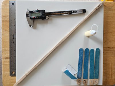
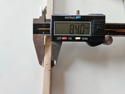
Rather than try to "eyeball" it, I decided to draw some guidelines along the shaft, sand the corners to the lines, making an octagon, then finish by rounding of 7 sides. So, first step - take measurements of the thickness at the joint and just below the sheave block (in both dimensions since the shaft is not exactly square, but a little rectangular - not by much, but enough).

20250412_140920.jpg

Many people think that you can turn a square into a rectangle by dividing each side into thirds and then connecting the diagonal corners. That doesn't work - the diagonal sides will end up wider than the remainder of the original sides. So, you must take the measurement across the face, multiply by 0.707, and mark a line that distance from each corner. If you don't know how I came up with 0.707, let me know and I'll post a little trig 101 lesson. :D

20250412_141147.jpg

20250412_141126.jpg

The extension piece at the bottom doesn't taper, so I could use the same measurements at the joint and at the foot. Then, connect the lines ...

20250412_143136.jpg

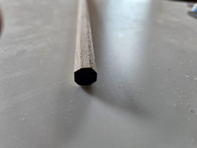
... and sand the corners to the lines, forming an octagonal cross section.

20250412_144921.jpg

After sanding it round, except for the forward face, I sanded the very top portion above the sheave. This I did by eye as it is relative small in diameter. Then I held the flat side of the mast against the table and placed the mast step (glad I hadn't glued it in yet ROTF) on the foot and used it to mark guidelines on the end to make a tenon that would fit into the slot in the step.

20250412_165651.jpg

Using those marks, I cut a tenon to fit and gave the mast a final sanding. I blended the flat face into a completely round section near the top because I figured it should be round to allow the yard to be easily swung from side to side.

20250413_111753.jpg

20250413_111919.jpg

20250413_111738.jpg

It sounds like a lot of work, but was really only about an hour or so. It took me longer to make this entry into the log than it did to shape the mast! ROTF

So that was my diversion - the baby woke up and it was back to chasing!
 
Mast

@JBB , this one's for you! ;)

Our 14 mo. old great grandson came for a sleepover Friday night - yay! I thought I would take a break from deck boards and do something quick and easy while he napped. (To be honest, though, he's just started walking and after chasing that little rascal around all morning, we're the ones who needed a nap! o_OSleep ROTF)

I decided to tackle the mast. It's provide in two pieces because the full length mast wouldn't fit into the box. It's a twice-lasered piece to allow tapering in both dimensions.

View attachment 513461

First step was to clean up all the char so I could see pencil marks on it.

View attachment 513462

Next get a good fit for the mortise and tenon on the extension and glue it in place.

View attachment 513464

According to Dr. Bischoff, the remains of the mast found in the Oseberg (the lower third or so) had a cylindrical cross section except for the forward face which was flat. The mast likely started out as a square beam, was made octagonal and then rounded, leaving the forward face flat. It is presumed this was dong to give a bit more mass to the forward side, making the mast a bit stronger.

Rather than try to "eyeball" it, I decided to draw some guidelines along the shaft, sand the corners to the lines, making an octagon, then finish by rounding of 7 sides. So, first step - take measurements of the thickness at the joint and just below the sheave block (in both dimensions since the shaft is not exactly square, but a little rectangular - not by much, but enough).

View attachment 513474

Many people think that you can turn a square into a rectangle by dividing each side into thirds and then connecting the diagonal corners. That doesn't work - the diagonal sides will end up wider than the remainder of the original sides. So, you must take the measurement across the face, multiply by 0.707, and mark a line that distance from each corner. If you don't know how I came up with 0.707, let me know and I'll post a little trig 101 lesson. :D

View attachment 513479

View attachment 513480

The extension piece at the bottom doesn't taper, so I could use the same measurements at the joint and at the foot. Then, connect the lines ...

View attachment 513482

... and sand the corners to the lines, forming an octagonal cross section.

View attachment 513484

After sanding it round, except for the forward face, I sanded the very top portion above the sheave. This I did by eye as it is relative small in diameter. Then I held the flat side of the mast against the table and placed the mast step (glad I hadn't glued it in yet ROTF) on the foot and used it to mark guidelines on the end to make a tenon that would fit into the slot in the step.

View attachment 513485

Using those marks, I cut a tenon to fit and gave the mast a final sanding. I blended the flat face into a completely round section near the top because I figured it should be round to allow the yard to be easily swung from side to side.

View attachment 513486

View attachment 513487

View attachment 513488

It sounds like a lot of work, but was really only about an hour or so. It took me longer to make this entry into the log than it did to shape the mast! ROTF

So that was my diversion - the baby woke up and it was back to chasing!
His Russ,

That looks great, I've been wondering how to do that.

Steve
 
Deck boards (cont'd)

Work continues on the deck boards - this is going to take a while.

The next step was drilling treenail holes. I had the opportunity to use my new toy - the Arrowmax drill. I mounted it on a piece of plywood to make a larger table. I found that even with a fence, there is just enough play in the spindle assembly that the drill bit tended to wander slightly. Plus, the unit would bind when using the handle to lower the spindle (maybe a bit of wax on the rails would help that), so I had to use a different grip on the spindle to minimize bit wandering and keep it from binding. Once I figured out a good method, drilling went fine. Despite the shortcomings of the drill press frame, I still think the Arrowmax will shine when handheld like a pencil for tight locations. I think it would beat a pin vise, especially with the number of rivet holes in the strakes (yet to come).

View attachment 513446

Once all the holes were drilled, the next step was to get the deck boards sitting at the same level with respect to the bitis. Pavel shows doing this in his videos. There is no standard amount to remove, so each set requires repeated test fittings as you sand. Five minutes on a table saw with a piece of scrap created a sanding block that does the trick rather quickly.

View attachment 513448

View attachment 513450

View attachment 513452

To be continued...
Hi Russ,

I like the sanding block idea, it has to be way better than filing it by hand.

Steve
 
Mast

@JBB , this one's for you! ;)

Our 14 mo. old great grandson came for a sleepover Friday night - yay! I thought I would take a break from deck boards and do something quick and easy while he napped. (To be honest, though, he's just started walking and after chasing that little rascal around all morning, we're the ones who needed a nap! o_OSleep ROTF)

I decided to tackle the mast. It's provide in two pieces because the full length mast wouldn't fit into the box. It's a twice-lasered piece to allow tapering in both dimensions.

View attachment 513461

First step was to clean up all the char so I could see pencil marks on it.

View attachment 513462

Next get a good fit for the mortise and tenon on the extension and glue it in place.

View attachment 513464

According to Dr. Bischoff, the remains of the mast found in the Oseberg (the lower third or so) had a cylindrical cross section except for the forward face which was flat. The mast likely started out as a square beam, was made octagonal and then rounded, leaving the forward face flat. It is presumed this was dong to give a bit more mass to the forward side, making the mast a bit stronger.

Rather than try to "eyeball" it, I decided to draw some guidelines along the shaft, sand the corners to the lines, making an octagon, then finish by rounding of 7 sides. So, first step - take measurements of the thickness at the joint and just below the sheave block (in both dimensions since the shaft is not exactly square, but a little rectangular - not by much, but enough).

View attachment 513474

Many people think that you can turn a square into a rectangle by dividing each side into thirds and then connecting the diagonal corners. That doesn't work - the diagonal sides will end up wider than the remainder of the original sides. So, you must take the measurement across the face, multiply by 0.707, and mark a line that distance from each corner. If you don't know how I came up with 0.707, let me know and I'll post a little trig 101 lesson. :D

View attachment 513479

View attachment 513480

The extension piece at the bottom doesn't taper, so I could use the same measurements at the joint and at the foot. Then, connect the lines ...

View attachment 513482

... and sand the corners to the lines, forming an octagonal cross section.

View attachment 513484

After sanding it round, except for the forward face, I sanded the very top portion above the sheave. This I did by eye as it is relative small in diameter. Then I held the flat side of the mast against the table and placed the mast step (glad I hadn't glued it in yet ROTF) on the foot and used it to mark guidelines on the end to make a tenon that would fit into the slot in the step.

View attachment 513485

Using those marks, I cut a tenon to fit and gave the mast a final sanding. I blended the flat face into a completely round section near the top because I figured it should be round to allow the yard to be easily swung from side to side.

View attachment 513486

View attachment 513487

View attachment 513488

It sounds like a lot of work, but was really only about an hour or so. It took me longer to make this entry into the log than it did to shape the mast! ROTF

So that was my diversion - the baby woke up and it was back to chasing!
Quality work Russ
 
I like the sanding block idea, it has to be way better than filing it by hand

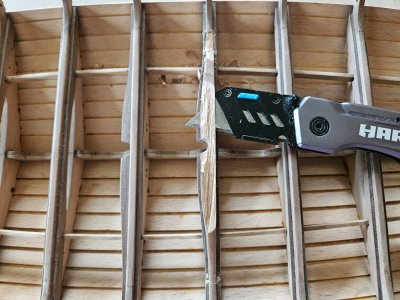
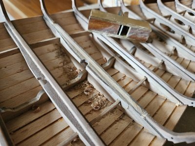
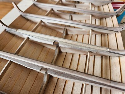
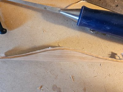
Yes, it worked out well. Even though all the decking ledges were placed down against the stringers, there were still a couple that were so high that I would have had to sand more than half way through the deck boards, so I had to get my 1/8" chisel out and pare the ledges down a bit. Worked out well.

Quality work Russ

Thank you Grant!
 
Back
Top