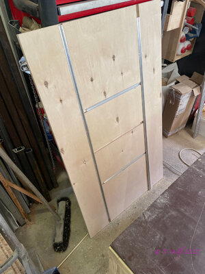
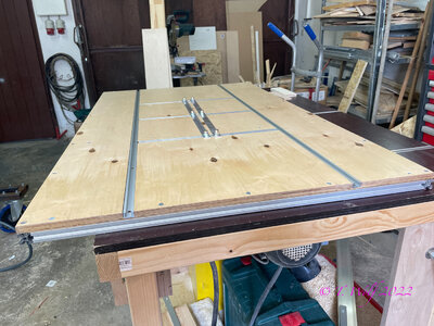
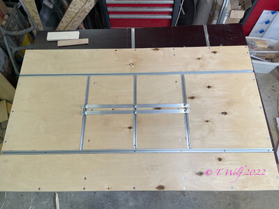
Did you make it, or did you purchase it with the t-slots?Hello Korsar, what exactly do you want to know?
-

Win a Free Custom Engraved Brass Coin!!!
As a way to introduce our brass coins to the community, we will raffle off a free coin during the month of August. Follow link ABOVE for instructions for entering.
-

PRE-ORDER SHIPS IN SCALE TODAY!
The beloved Ships in Scale Magazine is back and charting a new course for 2026!
Discover new skills, new techniques, and new inspirations in every issue.
NOTE THAT OUR FIRST ISSUE WILL BE JAN/FEB 2026
You are using an out of date browser. It may not display this or other websites correctly.
You should upgrade or use an alternative browser.
You should upgrade or use an alternative browser.
POF La Palme (L'Amarante) Corvette 1744 1:36 (Ancre Monograph) by Tobias
- Joined
- Apr 20, 2020
- Messages
- 6,257
- Points
- 738

sorry my mistake
Last edited:
- Joined
- Apr 20, 2020
- Messages
- 6,257
- Points
- 738

Tobias my dear friendHave a wonderful good Sunday evening everyone. A little update, this week I started with the rear, I can tell you it's pretty tricky, well that's how I wanted it. I had to redo frame 52 and 53 on the port side. The following error happened to me with the No. 52: I misinterpreted the plan and milled the notch for the fashion piece a little too deep. For No. 53, I glued the double frames mirror-inverted.
View attachment 293756
View attachment 293755
View attachment 293757
View attachment 293758
View attachment 293762
View attachment 293759
View attachment 293760
View attachment 293761
View attachment 293763
See you soon.
Ps.: Thanks to everyone for your comments and likes.
I need your help
What is the height of the part marked in the pictures with a black line and an arrow? In the drawing it is not clear where exactly it is measured and is it the height of the next four below it?
Many thanks in advance
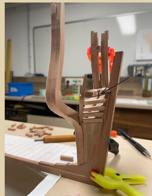
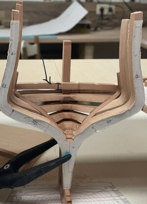
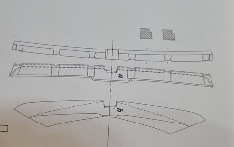
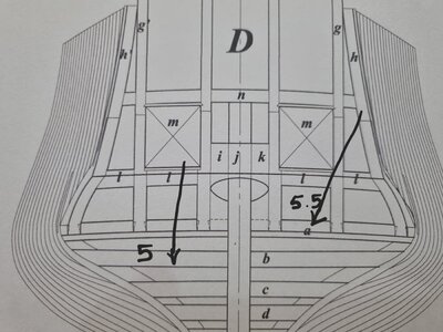
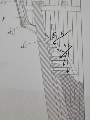
Hi Shota, you can actually take all the measurements from the plan, but I admit that you have to switch back and forth between 2 or 3 plans from time to time.
Maybe a few pictures will shed some light on this.
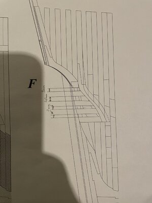
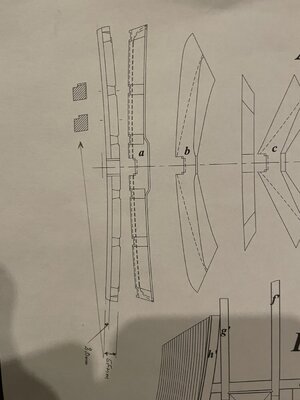
In the ascending wood you have the notches (picture below) for the crossbeams a, b, c, d and e (picture above) and if you have done everything correctly when preparing, you won't be able to get out. Use a piece of 7mm for crossbeam a, then glue it and cut out the top view first.
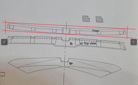
Then cut out the side view and glue it on and then work out the curvature with a sander, e.g. a spindle sander.
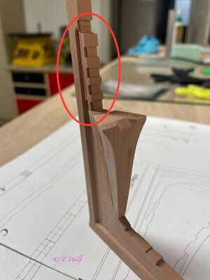
A little hint in the plans you will always find grey shaded pictures (see second picture) this is the cross-section of the component and here you can measure the height and width of the beam, for example.
Here is another picture I think I have not published maybe it helps a little.
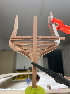
Maybe a few pictures will shed some light on this.


In the ascending wood you have the notches (picture below) for the crossbeams a, b, c, d and e (picture above) and if you have done everything correctly when preparing, you won't be able to get out. Use a piece of 7mm for crossbeam a, then glue it and cut out the top view first.

Then cut out the side view and glue it on and then work out the curvature with a sander, e.g. a spindle sander.

A little hint in the plans you will always find grey shaded pictures (see second picture) this is the cross-section of the component and here you can measure the height and width of the beam, for example.
Here is another picture I think I have not published maybe it helps a little.

- Joined
- Apr 20, 2020
- Messages
- 6,257
- Points
- 738


I will have to sit down and study the data thoroughly and properly plan the work
Dear Tobias, Thank you very much for your detailed answer, I really appreciate itHi Shota, you can actually take all the measurements from the plan, but I admit that you have to switch back and forth between 2 or 3 plans from time to time.
Maybe a few pictures will shed some light on this.
View attachment 408517
View attachment 408518
In the ascending wood you have the notches (picture below) for the crossbeams a, b, c, d and e (picture above) and if you have done everything correctly when preparing, you won't be able to get out. Use a piece of 7mm for crossbeam a, then glue it and cut out the top view first.
View attachment 408526
Then cut out the side view and glue it on and then work out the curvature with a sander, e.g. a spindle sander.
View attachment 408519
A little hint in the plans you will always find grey shaded pictures (see second picture) this is the cross-section of the component and here you can measure the height and width of the beam, for example.
Here is another picture I think I have not published maybe it helps a little.
View attachment 408520
I will have to sit down and study the data thoroughly and properly plan the work
Last edited:
I wish you all a wonderful evening.
I've been very busy in the last few days and couldn't do anything in the shipyard, perhaps some of you will remember this picture.
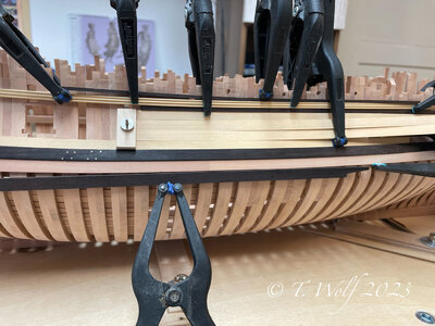
There were a lot of suggestions and constructive criticism about the colouring of the plank between the whales, for which I am very grateful. I thought long and hard about whether to make it black, as most of you suggested.
What can I say, I removed it and I'm glad I took this step. There was one suggestion that I personally really like and I think I will go down that route.
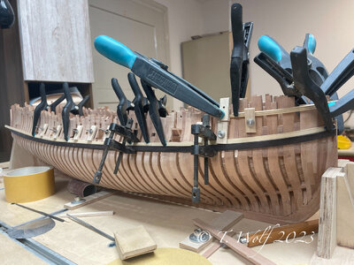
It won't be black like 99% of the L'Amarante built. Here I would like to take Christian @AnobiumPunctatum suggestion and will do it with a boxwood plank.
I'm glad about your feedback, that's what this forum is all about.
I've been very busy in the last few days and couldn't do anything in the shipyard, perhaps some of you will remember this picture.

There were a lot of suggestions and constructive criticism about the colouring of the plank between the whales, for which I am very grateful. I thought long and hard about whether to make it black, as most of you suggested.
What can I say, I removed it and I'm glad I took this step. There was one suggestion that I personally really like and I think I will go down that route.

It won't be black like 99% of the L'Amarante built. Here I would like to take Christian @AnobiumPunctatum suggestion and will do it with a boxwood plank.
I'm glad about your feedback, that's what this forum is all about.
That’s superb work Tobias. Well done.
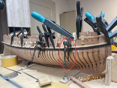
Hi Oliver,As usual great looking work. Will you please let me know if these clamps are hand made or where I purchase them.
thanks!
View attachment 409392
These are called Machinist/Toolmakers Parallel Clamps. While you can certainly make it yourself, here is the link on Amazon (not necessary for you to purchase from there
That was quick! Thanks Jim it really helps when you know the name of a thing in order to search for it!Hi Oliver,
These are called Machinist/Toolmakers Parallel Clamps. While you can certainly make it yourself, here is the link on Amazon (not necessary for you to purchase from there)
Hi Oliver, Jim has already explained everything. I bought them from a German manufacturer, but I would like to build some myself from wood.
Thanks Tobias. I too am deciding on how best to make some. I’ve looked at a bunch of YouTube videos for insight… we’ll see.Hi Oliver, Jim has already explained everything. I bought them from a German manufacturer, but I would like to build some myself from wood.
Here you go everyone who wants to make your own
 www.homews.co.uk
ToolmakersClamps, making. Conventional and Single sided. 1
Method of making, and dimensions for, both conventional and single sided toolmakers clamps.
Attachments
- Joined
- Aug 8, 2019
- Messages
- 5,585
- Points
- 738

I have those toolmaker clamps too, but most of the time I use my homemade clamps of wood.
Post in thread 'Hohenzollernmodell 1660-1670 Scale 1/75 POF build by Stephan Kertész (Steef66)' https://shipsofscale.com/sosforums/threads/hohenzollernmodell-1660-1670-scale-1-75-pof-build-by-stephan-kertész-steef66.11344/post-299974
And I believe Christian @AnobiumPunctatum made some to.
Post in thread 'Hohenzollernmodell 1660-1670 Scale 1/75 POF build by Stephan Kertész (Steef66)' https://shipsofscale.com/sosforums/threads/hohenzollernmodell-1660-1670-scale-1-75-pof-build-by-stephan-kertész-steef66.11344/post-299974
And I believe Christian @AnobiumPunctatum made some to.
- Joined
- Oct 15, 2017
- Messages
- 1,191
- Points
- 443

Hi Tobias, I love your own decision to accent with Boxwood, rather than the black inner wale!
Jim, Tobias and Stephan, I have never seen answers come back so quickly in assisting a member. This IS teamwork! But officially, Jim wins the race!
Jim, Tobias and Stephan, I have never seen answers come back so quickly in assisting a member. This IS teamwork!

It just happens I was near my PC, therefore jumped to answer...but you are certainly correct, it is teamwork! SOS is a unique forum, where we strive to help each other!
Good evening everyone.
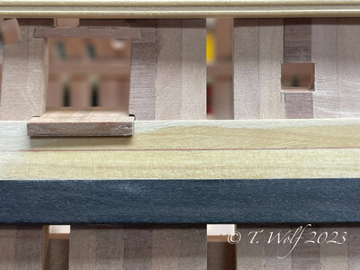
Attaching the top moulding and the first planks, here I use the tissue paper again, this time the red-brown one. To get a contrast between the moulding (boxwood) and the planking (also boxwood) I have attached a 1mm thick strip below the moulding. And now a few pictures with lots of clips and clamps.
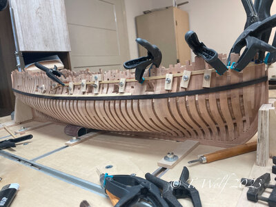
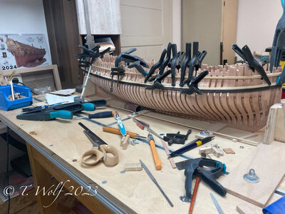
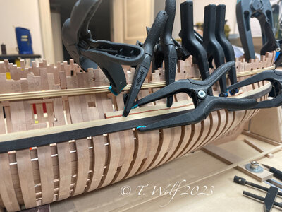
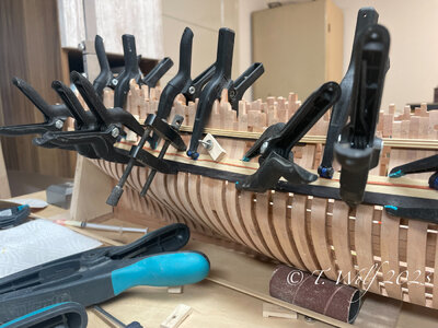
Here is a picture when the paper is removed.
Ken @Hoss6262 , yes Jim did the running, I was busy in the workshop.
Attaching the top moulding and the first planks, here I use the tissue paper again, this time the red-brown one. To get a contrast between the moulding (boxwood) and the planking (also boxwood) I have attached a 1mm thick strip below the moulding. And now a few pictures with lots of clips and clamps.


Here is a picture when the paper is removed.

Ken @Hoss6262 , yes Jim did the running, I was busy in the workshop.
I can only agree with you Jim SOS is a wonderful forum. It's a place to feel good, you get help, constructive criticism, valuable suggestions and the knowledge of builders is gladly shared, last but not least -> good mood and humour.It just happens I was near my PC, therefore jumped to answer...but you are certainly correct, it is teamwork! SOS is a unique forum, where we strive to help each other!


