-

Win a Free Custom Engraved Brass Coin!!!
As a way to introduce our brass coins to the community, we will raffle off a free coin during the month of August. Follow link ABOVE for instructions for entering.
-

PRE-ORDER SHIPS IN SCALE TODAY!
The beloved Ships in Scale Magazine is back and charting a new course for 2026!
Discover new skills, new techniques, and new inspirations in every issue.
NOTE THAT OUR FIRST ISSUE WILL BE JAN/FEB 2026
You are using an out of date browser. It may not display this or other websites correctly.
You should upgrade or use an alternative browser.
You should upgrade or use an alternative browser.
POF La Palme (L'Amarante) Corvette 1744 1:36 (Ancre Monograph) by Tobias
You have a very nice workshop, Tobias. Your models owned such a place.Hello dear friends,
a big thank you to everyone who has been following my build of La Palme over the last few months, leaving great comments and liking it.
Well, the time has come, the little Corvette is going on a longer break and I'm going to devote myself to Le Rochefort again. Finally, a few pictures, my goal of the construction phase has been achieved, as I had planned.
View attachment 428581
View attachment 428582
View attachment 428583
The workshop has been tidied up and Le Rochefort is ready on the left.
View attachment 428584
Regards, Peter
- Joined
- Aug 8, 2019
- Messages
- 5,585
- Points
- 738

I love your work and your workshop. There is enough room to walk around.
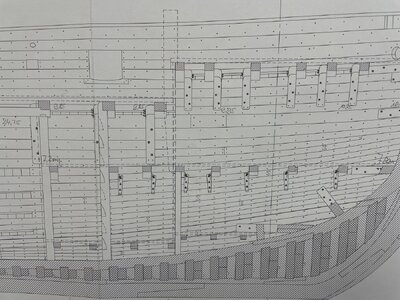
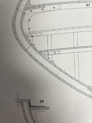
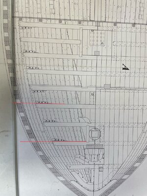
I also have a question about those beams of the floor you're making. I see That those iron brackets end up in the inner planking of the ship, see below.
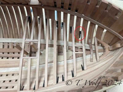
And not attached in the frames. I'm always understood that these bars, beams of this deck (I believe if I'm right, called the orlop deck) are a part of the construction to hold the ship together. On a Dutch ship these deck beams are connected with a dovetail connection because of that. Therefore is it not better to attach them ending in the frame?
I also have a question about those beams of the floor you're making. I see That those iron brackets end up in the inner planking of the ship, see below.

And not attached in the frames. I'm always understood that these bars, beams of this deck (I believe if I'm right, called the orlop deck) are a part of the construction to hold the ship together. On a Dutch ship these deck beams are connected with a dovetail connection because of that. Therefore is it not better to attach them ending in the frame?
Hello Stephan,
in fact it seems extraordinary to me. If we keep the plan in mind, we can see that not all iron angles end on the frames.
A comment from GD.
Quote: The position of these iron arches is not mandatory, it depends on the presence of the partitions, the torques for their anchoring and their opening angle. We just need to find a coherent synthesis regarding these criteria. The first beam is simply doweled, without curvature, and all the others are attached with dowels that are pinned to the clamp to remain removable.

- Joined
- Oct 23, 2018
- Messages
- 886
- Points
- 403

Hi Tobias,
this only make sence if you add some filling peaces between the frames. I would change this.
this only make sence if you add some filling peaces between the frames. I would change this.
Hi Tobias,
this only make sence if you add some filling peaces between the frames. I would change this.
Hello Christian,
your suggestion with the filler pieces is a good idea and will be implemented. When asked about this again at GD, in my case he also recommends the use of filler pieces, he also points out that it is not absolutely necessary that the iron curves are attached to this position as they are “small” loading bars and can be removed or moved are. The original plan was for me to take out a few frames to get a better look inside, so it wouldn't have mattered. However, it was a huge challenge to fit the beams exactly. On the other hand, I was worried about stability because, strictly speaking, a gap would have to remain free. Thank you again for your interest and your tips, you never stop learning.
This is every time the problem, when we modeler are not showing the inner planking on both sides.
These iron angles would be based on and bolted against the inner planking - but if you do not show the planking they are against the air
The same problem you have with the small lighter beams hwich would lay and based also against the planking and not the frames.
Very clean and accurate
In my opinion no filler pieces are necessary.......
No - also english and spanish ships used in later time iron knees - it is nothing else than a knee fixing a beam to the structure - like a hnaging wooden kneeThank you, gentlemen for all these postings and comments. I am learning a lot. So, was this a feature unique to French ships?
- Joined
- Jan 9, 2020
- Messages
- 10,566
- Points
- 938

Thanks Uwe.No - also english and spanish ships used in later time iron knees - it is nothing else than a knee fixing a beam to the structure - like a hnaging wooden knee
This is every time the problem, when we modeler are not showing the inner planking on both sides.
These iron angles would be based on and bolted against the inner planking - but if you do not show the planking they are against the air
The same problem you have with the small lighter beams hwich would lay and based also against the planking and not the frames.
Very clean and accurate
In my opinion no filler pieces are necessary.......
Uwe, you are of course absolutely right that the beams normally rest on the planks. I originally made the beams that way. I am not entirely satisfied with this solution. At Le Rochefort I added planks in the area of the beams. At the moment I don't have a real solution because the plan to open the fuselage isn't completely off the table yet, but I'm sure I'll come up with a solution that also looks aesthetic.
- Joined
- Jan 9, 2020
- Messages
- 10,566
- Points
- 938

Thank you, gentlemen - I appreciate the info. I asked the question, because the French have always been known to do things a little differently - take French cars as an example  - so I was wondering whether the same applied to French shipbuilding.
 - so I was wondering whether the same applied to French shipbuilding.
also the british produced "french cars" - especially when wood gets rare later on
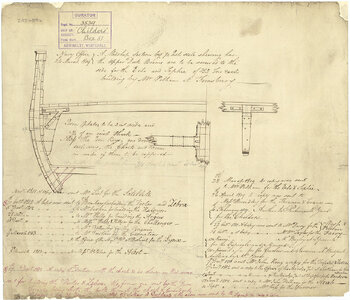
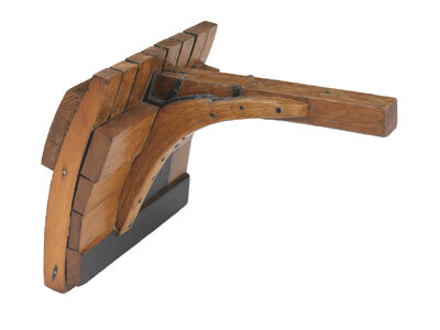
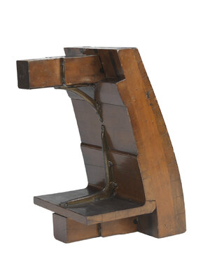
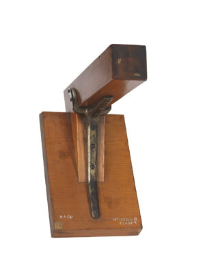
 www.rmg.co.uk


Collection Results | Royal Museums Greenwich
Hi Dan, thank you for taking the time to read my blog. Thank you also for your compliment, much appreciated.Phew, I finished reading Your blog to this point and have to congratulate You on this magnificent build! Not only is this a beautiful ship but the clean and exact work is stunning!!
- Joined
- Dec 3, 2018
- Messages
- 2,451
- Points
- 538

I have re-read this log once more, exciting and instructive.
You talked about a type of brass wire that is too soft when you made bolts/rivets.
Question, how did you solve this, can you recommend a supplier.
I'm thinking of trying this on my Rattlesnake which is 1-48.
I spend a lot more time reading various build logs now that I'm injured and on crutches.
Once again a lot to learn in your build logs.
Greetings Knut-


