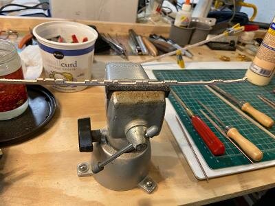
I thought you didn't know when, so I just simply remind you!!! LOLThank you Jim. But my birthday was last week.
Happy Birthday Mike!!!
-

Win a Free Custom Engraved Brass Coin!!!
As a way to introduce our brass coins to the community, we will raffle off a free coin during the month of August. Follow link ABOVE for instructions for entering.
-

PRE-ORDER SHIPS IN SCALE TODAY!
The beloved Ships in Scale Magazine is back and charting a new course for 2026!
Discover new skills, new techniques, and new inspirations in every issue.
NOTE THAT OUR FIRST ISSUE WILL BE JAN/FEB 2026
You are using an out of date browser. It may not display this or other websites correctly.
You should upgrade or use an alternative browser.
You should upgrade or use an alternative browser.
PROTOTYPE - H.M.S. Ontario Cross Section 2.0 [COMPLETED BUILD]
Kurt Konrath
Kurt Konrath
what oil finish do you use on this build?Thanks Jim, that is an oil finish that I use.
Kurt Konrath
Kurt Konrath
Mike you are inspiring me to get going on my Blandford, so I can then think down the road to this project at some point.
Mike - that is A LOT of work - my gosh - a very nice project and something for us to look forward to when this is released from prototyping. This makes my Blandford look like I am playing around with popsicle sticks.
Hopefully Mike gets back to this as soon as the virus goes on vacation Lol
Hopefully, Mike gets back from vacation but the virus sink into the abyss! Amen!!
Kurt Konrath
Kurt Konrath
Mike as silly question on ship design, why let water in just to have to pump out again?Hi Jim,
Thanks, the notches let water run back to the well house to be pumped overboard.
Mike
Otherwise too boring to be sailor LolMike as silly question on ship design, why let water in just to have to pump out again?
Boats leaked! The well, where the pumps are located, is the lowest point on the ship. The idea was to get the water to the well so it could be pumped out. The frames could prevent water from flowing, trapping it between adjacent frames and leading to rot. The notches allow free passage of water despite the frames.Otherwise too boring to be sailor Lol
Last edited:
- Joined
- Aug 10, 2017
- Messages
- 1,706
- Points
- 538

Hi Kurt,Mike as silly question on ship design, why let water in just to have to pump out again?
Both Zoltan and DocBlake are correct, the sailors used it for fill-in work when they finished scrubbing the decks.
Ships are under a lot of stress especially in bad weather, sea water forced it’s way between the planking and oakum caulking and ran down to the keel through notches in the frames to the sump at the low point of the ship. Rain also added to the problem.
- Joined
- Jul 22, 2017
- Messages
- 331
- Points
- 268

Those notches are called limber gates.Indeed, nice to see progress and start of the frames assembled on the kell. I have a question: The middle notch is where the frame goes to the keel. What are other two notches both sides (indicated with red arrows)?
View attachment 114958
Raymond
Thank you Ray, what is the purpose of limber gates?Those notches are called limber gates.
- Joined
- Jul 22, 2017
- Messages
- 331
- Points
- 268

Kurt Konrath
Kurt Konrath
OK, I understand the purpose now, to allow water to flow inside the hull between frames to the well house for pumping out.
For some reason I was thinking the opening were to exterior of hull, not interior of hull.
I see said the blind man to the deaf sailor.
For some reason I was thinking the opening were to exterior of hull, not interior of hull.
I see said the blind man to the deaf sailor.
Kurt Konrath
Kurt Konrath
Any updates on status of the cross section build?
- Joined
- Aug 10, 2017
- Messages
- 1,706
- Points
- 538

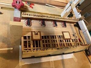
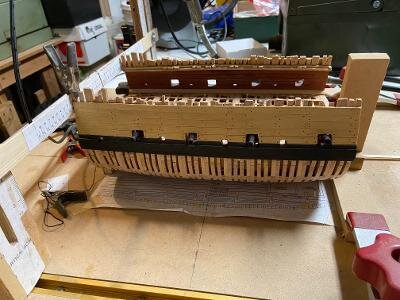
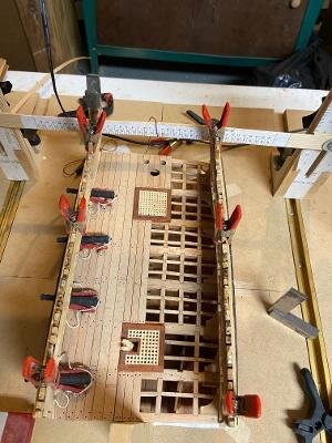
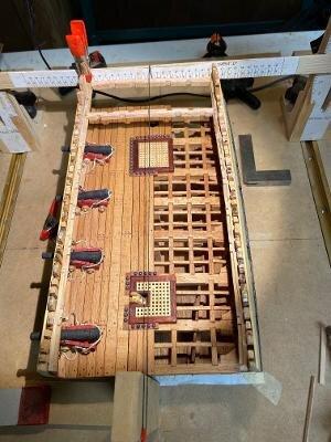
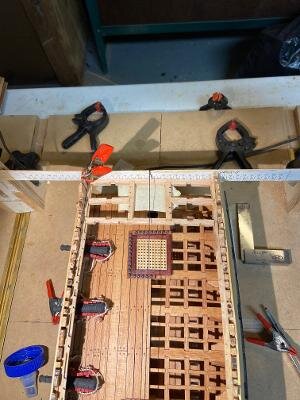
Hi Kurt, the cross-section has been on the shelf for a while, but I have resumed work on the lower deck. The guns were made by Mike Shanks with his CNC machine and the parts fit together perfectly; due to arthritis I just rigged the guns with breaching ropes. The drawings include details to fully rig the guns. They are installed as shown in the following photos. The upper deck clamps are also installed.
feel better , Mike
Glad to see you back at her, Mike! Looks great!
- Joined
- Aug 10, 2017
- Messages
- 1,706
- Points
- 538

Upper Deck Framing
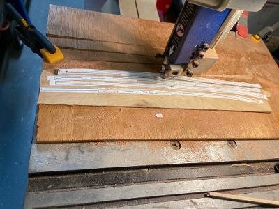
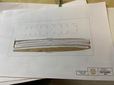
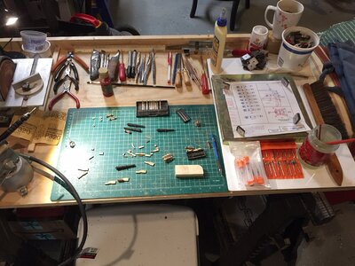
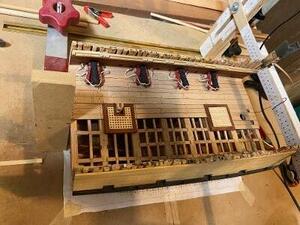
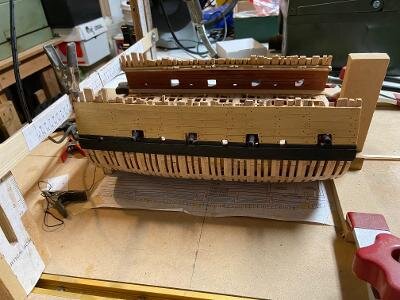
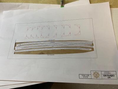
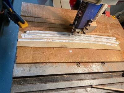
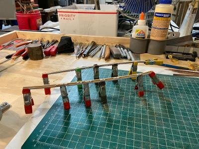
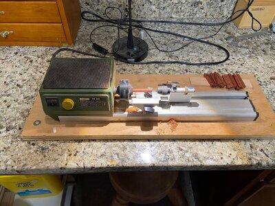
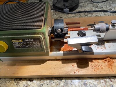
The upper deck framing is a lighter structure than the lower deck, it does not have the weight of the cannons to support. The ten deck beams are shown in the first two photos. The second photo shows the beams being checked for length and fit. The next two pictures show the beams with the notches for the carlings installed I stopped there to make the deck support columns with my Proxxon lathe as shown in the next group of photos along with the currant sate of the framing.
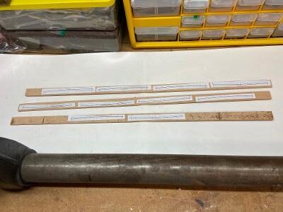
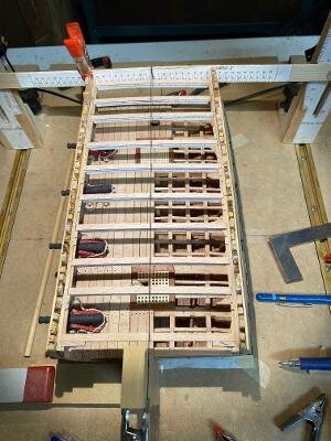
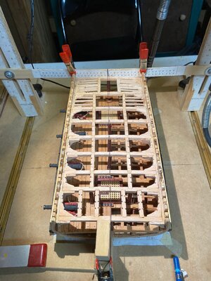
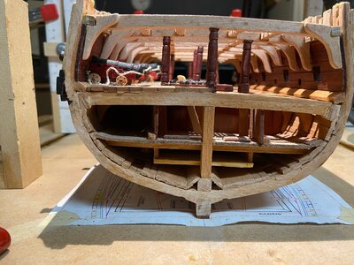
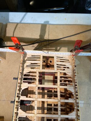
The upper deck framing is a lighter structure than the lower deck, it does not have the weight of the cannons to support. The ten deck beams are shown in the first two photos. The second photo shows the beams being checked for length and fit. The next two pictures show the beams with the notches for the carlings installed I stopped there to make the deck support columns with my Proxxon lathe as shown in the next group of photos along with the currant sate of the framing.


Nice, Mike!


