SAINT PHILIPPE 1693 in 1/64 PoB by Iterum

Today I workt on the deadwood - to be precisely: the dead dead wood ;) I do talk of the thickness under the planking where the distance is narrower than the 6mm of the given birch plywood.

Of intrest is onlv the distance from the keel up until the frame is 6mm of width:

IMG-20200321-WA0037.jpeg
C31 Ar. 37,5mm

IMG-20200321-WA0038.jpeg
C30 Ar. 33,2mm

IMG-20200321-WA0039.jpeg
VIII Ar. 21,5mm

IMG-20200321-WA0040.jpeg
VI Ar. 7mm

At VAr. it is 0mm. So I can draw this line to cut off this narrowpart from the centerboard and add some 3mm plywood what is completly right in thickness.
 
Thanks fot this question, Nigel! I think in terms of practicability...

...hopefully: The hole centerboard is not a very handy pice of wood in particular at a disk sander. The nearly 850mm LONG centerboard will be no so easy to handel than the 200 x 200mm deadwood inlay I do plan to extract from the centerboard.
 
The most intersting question of this plan in my ooint of view shifted to the hight of the UD and QD.

1st idea The hight of the "outside decks"
When I am looking on this contemporary 80 gunnship model I do think the distance between the wales are always the same:

Polish_20200321_230436456.jpg

According to this the upper handrail of the Lemineur SP is too close to the wale below it:
Polish_20200321_230922147.jpg
The distances between the wales are really differend:
from 3nd wale from L.F. to the 3rd wale we have got a distance of 30mm
between the 4th and the 5th wale there are 22mm
between the 6th snd the 7th wale there are only 12mm left.
So my eyesight is bad but my feeling was right, hopefully...

2nd The arkanthus bud under water
On the other hand thsre is an feature below the side gallery I dislike very much iin the Ancre plan:

Polish_20200321_233324211.jpg
The Acanthus bud is 3,2mm below the waterline and will be rotten very fast permanently in the wet.

In the original decoration drawing the bud is clearly over the waterline:
Polish_20200321_233021104.jpg

as the original drawing is scaled about 1/125 the vertical distance from the bud's lower end to the L.F. is about 7mm what gives us 13,67mm in 1/64. Bythis the hole side gallery has to be lifted 3,2mm to get the bud in a first step out of water. Then we have to lift it another 13,67mm to come to the place where the sidegallery had to be.

So we add both figures together (13,67 + 3,2) and by this we get a factor of 16,87mm we have to lift the sidegallery. As thd top of the crone is identical with the top handrail we have to lift this and the hole structure folling its movement, too. So the cemplete rail has to be pushed vertically up.

3rd the sudden idea of an ergonomical solution:

If we look at the lack of hight at the wales (30 - 22) + (22 - 12) = 8 + 10 = 18.
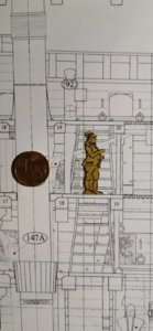
So we would have to rise the MD by 8mm and the UD by 10 to get the equal distance between all wales. There is no reason why the MD is quite lower than the LD. Why should this happen? (It is quite interesting that the only drawibg of the Comte de Échelle (RNguys know him as Mr McScale) is drawn into the very front of the upper deck where no F'c'st'l deck beams to crush his skull. Tomorrow I'll copy him from the pland and cut him out to get an ergonomical proof of the inner hull.

4th the less radical solution.
Not to bee too radical I think about leaving the MD as it is and rising the UD only to the same hight the MD is drawn. By this we get a 10mm lifting of the upper handrail (not any 18mm push).
Due to this we lift the arkanthus but only by 10mm instead of 13,67mm so the bud is definitely out of the flood but not too much and risen in some dramatically brainless way to do so.

5th the follow ups:

I will have also to do the changings to the bodyplan for each single bulkhead...
 
Interesting stuff.I would say though that LF is at maximum theoretical payload.The ship would rarely see this.That is why the depth markings at bow and stern only start below this.The contemporary model can only be taken with a pinch of salt.It shows all the wales of equal scantling,this is incorrect,they reduce in width and thickness as you go up the vessel.

Kind Regards

Nigel
 
Interesting stuff, vey very helpfull Nigel, thank you so much.

I would say though that LF is at maximum theoretical payload.The ship would rarely see this.That is why the depth markings at bow and stern only start below this.
That is were I do clearly agree - but I would change it/draw it down by something like 5mm up when I have got the panked hull on timbers under the rising keel infront of my "hight marker" (here a picture as I am unshure about my translation skills) :
Polish_20200322_110134295.jpg

So I am absoloutly shure about the parallelity of surface and L.F. and can lift it something like 5mm.

The contemporary model can only be taken with a pinch of salt.It shows all the wales of equal scantling,this is incorrect,they reduce in width and thickness as you go up the vessel.

Kind Regards

Nigel
Okay Nigel that is some interesting argument to me because I think you are right - in the part of reducing the distance between the wales. But what about this drawing - it also shows a much higher distance drom the top of the UD gunport framing to the handrail above:
Polish_20200322_115113809.jpg
If we do go closer into the subject - we do find 1/4 of the space between the wales stayes after the cutting out of the gunport:
Polish_20200322_115157362.jpg

At the Lemineur plan you can easily figure out that the gunports do all cut into both wales below and above:
Polish_20200322_115712417.jpg

Polish_20200322_120041013.jpg

The model does show the same charactertistica.

So we do have got two contemporary sources for minimum an additive breadth of (minimum) one plank more between the 5th and the 6th wale. (I am searching around for pictures of contemporary shipmodels or drawings to proof my 4th plank theory but all the decoration plans do not show a elaborated number of planks in the UD of the drawing of the side gallery:
Polish_20200320_235130135.jpg

But I looked at the wrong end - at the
Polish_20200320_235216828.jpg
galleon detailing there I did find planks! So I will do my research in first class ships in here
Polish_20200320_224538730.jpg

Both pictures above were from my beloved 3rd rank ship:
Polish_20200320_234138993.jpg


Okay let's ask our bloodsucking friend from Sesamstreet:
Polish_20200322_121008778.jpg
Polish_20200322_122215572.jpg
at the LD we do count five planks
Polish_20200322_122215572.jpg
at the MD we do count five planks

at the UD we do count

One...

...

... two...

...

...THREE!

ff169223e8e602d2db1a412379425df8.gif


So from five to three is a lot not a very baroque way to do it being harmonic and in touch with mother nature &c...

So what can we do without treaing the hole planset down from the drawing board and jumping on it in full fire of our hate and strange it in a waste paper basket?

I could try to change only a bit of this hull.
What I will try is to copy the side of the hull and adding a fourth plank below those we have got now on frostpaper so we get a higher UD outside appearence between the wales. And by this let us have a look what benefit the hull's shape will have got from adding a width of 4,5mm...

What do YOU think about this @NMBROOK?
@Hubac's Historian You did look on hullsband plans for so many years what is your idea?

Thanks for the intrest - and sorry for the Sesamstreet wit - we need to hire more young modelship builders, don't we??? :D
 
Last edited:
But at SAINT PHILIPPE do touch the upper&lower wale...

Polish_20200322_135230559.jpg
the distance is drawn quite narrow and the top&bottom of the gunports frame

Polish_20200322_134332190.jpg
even at the original decoration design drawing.
 
Last edited:
So at the Les Vausseaux 1650-1850 I did find:
Polish_20200322_132516343.jpg
LE BON 1693 - 56guns

Polish_20200322_132617487.jpg
L'ECLATANT 1721 - 64guns

Polish_20200322_132657112.jpg
LE POMPEUX 1706 -

Polish_20200322_132741390.jpg
LE BOURBON 1720 74guns

Polish_20200322_133926461.jpg
LE TRITON 1728 - 64guns

All do have a heck of space between gunport and and wales...
 
Last edited:
On my walk trough the original and JCL drawings I found an interesting artefact:

There the area at the original drawing:
Polish_20200322_134332190.jpg

Lemineur placed a new gunport in the MD behind the breakhead bulkhead at plate 33
Polish_20200322_135230559.jpg

at Plate 45, too:
Polish_20200322_134726867.jpg

Polish_20200322_135958011.jpg
Plate 17

Polish_20200322_135909998.jpg
Plate 16

Polish_20200322_135752009.jpg
Even in the Framing Elevation

What does happen here? Why this gunport (that isn't shown in 4 of the 5 drawings above!)?
 
Last edited:
I did do it I - i built the "Comte de Échelle" and he walked all over the plan...

I figured out ONE scale figure hidden:
Polish_20200322_194207562.jpg
View attachment 139574
Redrawing it on thin frostpaper:
IMG-20200322-WA0054.jpeg

The Comte de Échelle and his Sovereign an a 1/4 Souscoin:
View attachment 139575IMG-20200322-WA0059.jpeg

A brand new sharp blade has to make it!
View attachment 139576IMG-20200322-WA0064.jpeg

Let's do it the Australien way
IMG-20200322-WA0070.jpeg
View attachment 139577
"Do it! Damnd guy's do it!"
View attachment 139578IMG-20200322-WA0072.jpeg
My end of the level enemy - The nose and face:
View attachment 139579IMG-20200322-WA0074.jpeg
It does work!
View attachment 139580IMG-20200322-WA0076.jpeg
I didnt expect myself to be able to build this small figure due to my thick glasses - but it does work:
View attachment 139581IMG-20200322-WA0080.jpeg
Here the prototype and the copy vis-a-vis:
View attachment 139583 o_O
Polish_20200322_193327536.jpg

You can see the heaviest block in the hole ship decorated with a classical Turk's heads craving:
View attachment 139564Polish_20200322_191018946.jpg
Polish_20200322_191159425.jpg
View attachment 139563
All in all it does fit only the middle artillery deck
View attachment 139582Polish_20200322_193540892.jpg
is sometimes quite dangerous to crush your skull on a beam...

View attachment 139568Polish_20200322_191533359.jpg
Do not touch it is a chimney!

View attachment 139564Polish_20200322_191243686.jpg
I am not really happy with some of the stairs... above is okay but below is a bit doubtfull:
View attachment 139566Polish_20200322_191341097.jpg

This isnt what Lloyds London would call "safty" :
Polish_20200322_200118112.jpg

Polish_20200322_191453058.jpg
View attachment 139569
This does look better - "Bimbim!"

View attachment 139567The figure was at least everywhere and I am quite happy with the result - so time for a short brake in the Mediteranian evening sun:
IMG-20200322-WA0215.jpeg

Have a nice evening all together!
 
And I found SAINT PHILIPPE 1693 - 90 guns again:

View attachment 139491

and let's count the planks between the wales
View attachment 139492

astonishingly THREE!

Hello,
I really think that there is a point when construction must begin: errors will work themselves out and confusion will dissipate.
Yes one must study the plans, etc... this said, the more you look, the more confused you will get.
Furthermore, one should certainly not compare iconography and what amounts to artist's renderings to the set of plans provided in the monograph to determine the number of planks or the spacing between wales.
These artist's renderings were likely projects for the decor of the ship: besides that, they would have very little value in regards to actual ship structure, number and placement of gun-port, number of planks covering the framing, etc....
This is just my opinion, but I do believe you should get started. Problems and questions will arise, solutions and compromises will be found.
There may be errors in drafting, issues with different waterlines: these are actually representing nothing concrete as they are used to work out the volume or shape of the hull in drafting the plans, but the ship can be built as they are not commonly used for the construction of the model.
Using the longitudinal elements patterns (keel, stem, deadwood, rising wood, etc...) and the frame patterns provided will allow you to proceed with the construction.
Model ship building from plans is often about problem solving: whether they are problems with the plans, misinterpretations of the plans as well as other "self inflicted" issues.
Other have built or are building this ship. Every plan, even the best ones (without errors) present challenges to modelers. Ship building from plans also calls for a bit of imagination from the modeler.
I would think that the best approach would be to communicate with other builders in order to find out how they have managed to get as far as they have in the construction of their ship.

Just my 2 cents.
Cordially.
G

PS: will you be building this as a planked of bulkhead or planked on frame ship?
 
Heinrich Gilles can't of beat me to what I was going to say.The planks in the artworks,working from the known size of the lower gunports,are the thick end of 18 inches wide in places.This is impractical.I agree with Giles,the planks are only represented to decorate the drawing rather than factual evidence.The character having to duck under deckbeams on all but the main gun deck and officer's quarters is what I would expect.

Kind Regards

Nigel
 
Gilles,she will be a Pob build

OK!
So in this case, the basic structure of the model is the centerboard to tie the area between stem and sternpost and vertical sections (bulkheads).
As the vertical line-sections / drawings get crowded in some spot and as a result are difficult to use, the bulkheads can be designed/created from the actual frame drawings: taking the deck lines and other levels into account. I may be wrong but I see little use for waterlines.
The centerboard must of course be vertical, the bulkheads must be symmetrical from side to side. My understanding is that the actual waterline is not parallel to the keel so, if it is the case, the bulkheads may have to be set at 90 degrees angle to the waterline, not the keel. This can easily be determined studying the several plates in the set of plans. As far as working out the right volume lines for the hull, one can easily use templates corresponding to the bulkhead profiles. The position of the decks can be worked out from what is shown on the plans, etc.... etc.....

I am certainly not implying that PoB is an easier built, but...
Although the set of plans may contain errors, the ship can still be built. The proof can be seen with the other very fine 2 PoF models being built right here.
I would think that the main reason why Le Saint Philippe is not a popular project has nothing to do with the accuracy of the plans but more because of the complexity of the structure as a PoF built as well as the amount of decor: which in itself is enough of a reason to stay away from such ship for most modelers. This is further confirmed by the fact that building other such ship is not as widespread.

In the end, Yes, there is a time when one needs to take the jump and proceed with the construction.

Again, just my 2 cents.
G.
 
Hello,
I really think that there is a point when construction must begin: errors will work themselves out and confusion will dissipate.(...) .

Just my 2 cents.
Cordially.
G

PS: will you be building this as a planked of bulkhead or planked on frame ship?

Wow & thank you, Gilles, very much!
It will a quite straight forward PoB-Build...

The ideas you bring into the build are very importand I do work with them very seriously.

Thank you very very much.
 
Heinrich Gilles can't of beat me to what I was going to say.The planks in the artworks,working from the known size of the lower gunports,are the thick end of 18 inches wide in places.This is impractical.I agree with Giles,the planks are only represented to decorate the drawing rather than factual evidence.The character having to duck under deckbeams on all but the main gun deck and officer's quarters is what I would expect.

Kind Regards

Nigel
When checking the plan the middle gundeck wasn't so ergonomical too bad designed, Nigel - as we know people were not as tall as we are today something around 1.700 mm (the parade Potsdam "Langen Kerls" of the Prussian Royal Regmt. on Foot were announced to be 1.800mm to join.)
IMG-20200322-WA0193.jpeg

IMG-20200322-WA0196.jpeg
IMG-20200322-WA0156.jpeg

The size of the planks wide will be taken from the JCL drawing...

Thanks Guies - you made my day!

P. S. :
IMG-20200406-WA0005.jpeg
So as this guy is 28,5mm in 1/64 - he will be an impressive guy of 1.824mm. Tall ergonomical reference and due to this the deck's beams are complety okay!!!
 

Attachments

  • IMG-20200322-WA0159.jpeg
    IMG-20200322-WA0159.jpeg
    144.8 KB · Views: 3
Last edited:
At the Moment I do deal with a overscaled variation of
2000px-Coat_of_Arms_of_Kingdom_of_France.svg (1).png
the coat of arms of Royal Francehere as simplifies late version from the time of Louis XVI.(Louis the headless) - also simplified by the artist, too. And as for some of us we do meet this item on the ships hull several times:
IMG-20200406-WA0048.jpeg
Here on the starboard side gallery. As it is a pair of colliers of the nobeles french knight orders:

2112px-Collier_de_chevalier_de_l'ordre_du_Saint-Esprit_et_son_écrin_(Louvre,_OA_11859).jpg
The Ordre of the Holy Ghost

ESPRIT-JOAILLERIE-MUSÉE-LÉGION-DHONNEUR-7.jpg
and the Order of Saint Michael we have to deal with a big amount of details and finest baroque court juwelier's craftmanship.

As both colliers stucked into each other we have to identify the details first. Both do have got an huge amount of irritating detailing work. Screenshot_20200406_132518_com.android.chrome.jpg
H is the letter H as the order was founded by King Henry the letter H is in the flames of the holy ghost...

Screenshot_20200406_132402_com.android.chrome.jpg
the second is the fleur-de-lys. A very fine detailed kind of item with an arcanthus leaf added as decoration.

And the third element is the classical Helmet, Flags and Spears symbol:

Screenshot_20200406_132419_com.android.chrome.jpg
some very complex item I will try to seperate into its single elements.

This is an very early issiue of the collier beautifully done - located at the Louvre/Paris.

Screenshot_20200406_132440_com.android.chrome.jpg
Also the cross is in a finer layout done than the later followers...

The Ordre of St. Michael is in his way an complex task to do, too:

ESPRIT-JOAILLERIE-MUSÉE-LÉGION-DHONNEUR-7.jpg
there I will need my wire bending skills very well.

1538578607.jpg

Here St. Michael kills the Devil that han desintegrated his appearence as a dragon into his ugly person as a fallen angle again tdue to facing his very end ( as in good Siegfried interpreatations the Fafner is again the giant that has changed into a dragon...
Att he moment I do work on an 1:2 or 1:3 model to get some feeling for the forms and problems - and in the very end getting a 1/64resin mould

Here today,'s humble progress:IMG-20200406-WA0032.jpeg
cut out from cards and
IMG-20200406-WA0038.jpeg
soaked with CAglue it is


IMG-20200406-WA0051.jpeg
doubled now and awaiting finescale carving to be ready to get into a mould of silicon...


Keep calm and build modelships.
 
Last edited:
Hello friends, I am still struggeling with the center board and the thickness of the deck's under board layer.

... so the project is still alive but on a non hurrying modus.
 
Back
Top