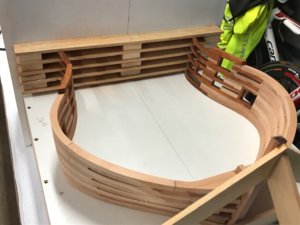
Saint-Philippe 1693-POF to the Monograph by Jean-Claude Lemineur by NMBrook-1/36

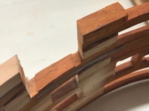
Michel I actually find it straight forward provided all measurements are constantly checked.The last frame was a problem as it had sprung out of shape.I put this down to the mortices being too tight.I assembled a frame this morning and noticed that if these joints are too snug the frame starts moving about so I trimmed a little more off the problem area.
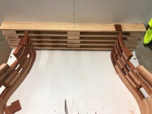
The next frame is now glued in position.No wedging required and everything lines up as it should.Next I have to complete works around the two gunports.The next frame will not be glued,it will be pinned with floating dowels,as this will be one of my movement joints.I plan to use plastic spacers temporally for set up purposes and the joint will be split and these removed before final assembly.
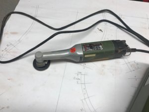
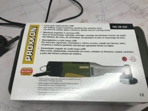
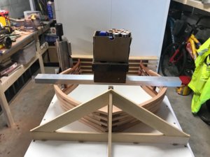
Lastly my new toy was delivered today,this enables me to work on fairing frames on mass,so from now on no fairing other than the area around the floor until a good chunk is assembled.

Kind Regards

Nigel
sp121.jpgsp122.jpgsp123.jpgsp124.jpg
 
Michel I actually find it straight forward provided all measurements are constantly checked.The last frame was a problem as it had sprung out of shape.I put this down to the mortices being too tight.I assembled a frame this morning and noticed that if these joints are too snug the frame starts moving about so I trimmed a little more off the problem area.
The next frame is now glued in position.No wedging required and everything lines up as it should.Next I have to complete works around the two gunports.The next frame will not be glued,it will be pinned with floating dowels,as this will be one of my movement joints.I plan to use plastic spacers temporally for set up purposes and the joint will be split and these removed before final assembly.
Lastly my new toy was delivered today,this enables me to work on fairing frames on mass,so from now on no fairing other than the area around the floor until a good chunk is assembled.

Kind Regards

Nigel
View attachment 115612View attachment 115613View attachment 115614View attachment 115615
Hi Nigel,

Curious how effective this one is. Looking already for some time at it.
 
Hi Maarten

The sander(grinder) is brilliant.I think it would dig in had I have left the guard in place as it's edge sits a couple of mm below the abrasive pad forcing you to have a steep angle of attack.The motor is only 100w and to be honest it is all that is needed with a 50mm disc.I have no intention of grinding metal,I have a 125mm grinder for that so I don't thinkthe motor will ever get hot.
I have used the machine to taper the thickness on one frame so far.I have been using a permagrit block to do this as the taper is 200mm long.It takes me a couple of hours to do this by hand,twenty five minutes with the sander,including fine tuning by hand.

Kind Regards

Nigel
Sounds like a great to to add to my stash for my future scratch project.
 
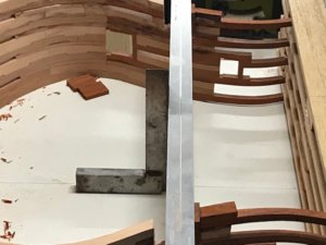
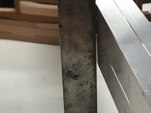
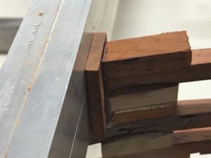
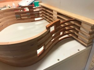
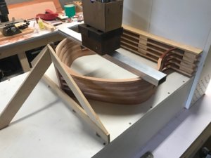
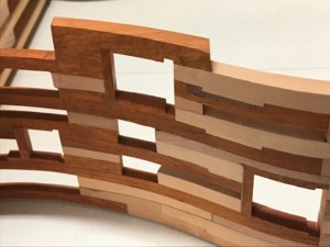
Continuing on the top frame was cut through completely on both sides to produce the gunports.I have found a junior hacksaw well suited to the task.The sturdy type with adjustable blade tension as the frame does not grab the blade like it would a razor saw.The sides are then trimmed with a scalpel.
The gunport heads are fitted as before with the aid of a piece of ali extrusion to ensure they are in line and also following the downward slope like the previous ports on the lower deck.
On a different note I have started planning what to do next.I have chosen to do the hawse timbers as I need to make these and the forward keel to unravel the relationship between keel and the most forward of frames as the drawings are a bit of a car crash in this area.After two hours of headscratching and trying to work out how JC Lemineur had arrived at his sections I finally sussed that the sections were all drawn at 90 degrees to the keel.The keel slopes when in the water and the frames are plumb.His point of reference made no sense to me and I have had to draw in his point of reference so I can lay his patterns on then trim them to suit the first frame :mad:
I have also worked out how to mill these in my big mill(too large for the Proxxon)to get the 1mm in 100mm slope on these wedge pieces.They fan out but nowhere near as much as other vessels.I will go into this in more detail when I start this area in earnest.

Kind Regards

Nigel

sp125.jpgsp126.jpgsp129.jpgsp128.jpgsp127.jpg
 
The more I follow your great build log, the more I have convinced myself that only desire will not be enough to start building a POF model. Without a full understanding of the basic construction of the ship's hull, this makes a really difficult, if not impossible at all. A build like yours definitely helps to gain some knowledge. Many thanks for sharing!
 
The more I follow your great build log, the more I have convinced myself that only desire will not be enough to start building a POF model. Without a full understanding of the basic construction of the ship's hull, this makes a really difficult, if not impossible at all. A build like yours definitely helps to gain some knowledge. Many thanks for sharing!

I amfraid you're exactly right, Jim!
Janos
 
Thank you Jim and Janos.I will be honest I am finding it hard work as there is only myself and Giancarlo building this vessel on the net.We are both forging a new path and the drawings contradict themselves in many areas.Probably the biggest issue is the framing design.Giancarlo has also discussed with me the aft frames are drawn wrong in that they should be double all the way down to the keel.I haven't got to the aft end yet other than working out how I am going to construct the counter timbers.
The problem I have is that the forward frames are shown as not true double frames at their base but the side elevation shows them as if they are.However a lot is dependant on where the side section is sliced through.The lower forward timbers of the frame run close to the false keel,are these shown in the section view?
Normally you would have a line with arrows on the plan showing the exact position the slice was taken through.No such arrows on the birds eye plan.
I remember a discussion about building a model for competition.Naviga rules state the model should follow the drawing no matter what.Even if you believe the drawing is wrong,you must follow the plan or you could loose marks.
I wonder how the judges would go on here,one view says one thing,another view says something different?
One thing you do get with Jean Boudriot monographs that you don't get here is drawings of the individual keel and frame components,none here to help unravel the problem.

Kind Regards

Nigel
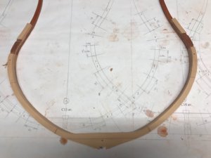
 
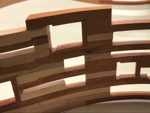
Final update of the weekend.The other sides (or tops as it is in the jig) were milled as I did for the last gunports and bonded in place.Again bottom cills to be inserted much later in the build as they penetrate internal and external planking.This would make final fairing next to impossible to do properly.
I have given the new area a rub over with the new long neck sander but have been mindful to keep away from the gunports or the thin tops of the frames.These areas are best taken care of in the final hand sanding to avoid mishaps and removal of too much stock in these delicate areas.

Kind Regards

Nigel
sp130.jpgsp131.jpgsp132.jpgsp133.jpg
 
NIgel,
This is indeed a PROJECT - your notes and member comments are very informative as well. Yes, you and Janos are building in the most rarified air of this hobby - taking it to its pyramidic top. These are brilliant challenges that you and a few others can achieve this level of skill steeped in indeed much research, and skills (and space haha)

Regards,
 
Michael
Thank you very much indeed for your kind words.You mention space,looking back I do feel I kind of lost my modelling mojo a little when I lost my workshop of 14 years when we relocated due to my job.Now I have regained the workshop and some stability I guess you could say this project is my way of celebrating:D

Kind Regards

Nigel
 
A little bit of a background to explain why I am doing what I am doing next.
Timber Movement;
This is a problem with plank on frame models,the problems get worse as the model gets larger or if the waist is fully infilled.Saint-Philippe's hull will be 1700mm long and is fully infilled along the waist.
Timber swells and shrinks depending on the humidity.It swells and shrinks much more across the grain then it does along it.This is even more prevalent with an absorbent timber like Pear.The issue with a fully framed model is that all the frames have the cross grain running along the model,but keel decks and planking etc all have the grain running along the length of the model.
Basically the different elements are trying to tear each other apart.After a thorough search to see what others have done,I have come across the following:

1-Control the humidity;I own the model not the other way round,I am not going to all the hassle of humidifiers,dehumidifiers etc.To much expense and what happens when the model is moved from one room to another?Move all the gadgets as well as a massive model?I would like to think that the model will outlive me,do I provide a care instruction package:rolleyes:

2-Sort it if it happens;yes this came up in my findings.Removing sections of a frame or running a razor saw through the skeleton to alleviate the pressure that has causing the deformation.Normally this starts with the keel bowing but could even be a crack or broken glue joint somewhere.This is not the way I want to proceed,I want to engineer the problem out best I can.What happens if the planking is on and you can't just run the saw through it!

3-Protect from moisture-Eventually the model will have finishes on but that will be years down the line so not viable.

4-Leave the joint between every 4th to 6th frame unglued.This is getting close to where I want to be but what if humidity increases?The unglued joint only protects against shrinkage.

5-My chosen solution,a movement joint to allow the timber room to swell after construction and also to shrink.Two very prominent professional modellers use these in their models so I am going to follow suit.

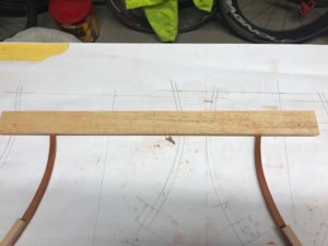
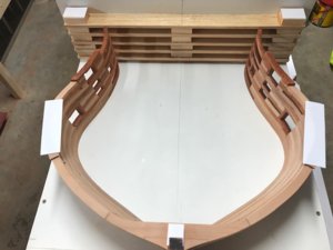
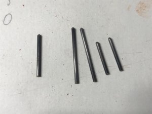
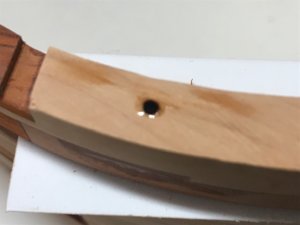
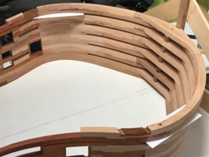
On to what I have done as I have encountered where the 1st movement joint is.Firstly 5 holes 1.5mm diameter were drilled right through the next frame assembly.Three in the frame,two in the temporary jig section.
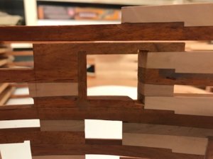
The frame was then placed in position and the holes drilled through 0.75mm plastic packers into the frame below.The frame infills have been made 0.75mm thinner to allow for the packs.The packs will be removed later on leaving a theoretical 0.75mm gap.
Into the holes 1.5mm carbon fibre rod was inserted to dowel these together.No glue was put on these.They need to float to allow movement.I did push them 2mm below the surface and put a drop of Cyano in.this only glues them to one section.
The idea of the dowels is that they hold everything in line during construction and because they still allow movement along the model,will stay in there permenantly.

Kind Regards

Nigel
sp134.jpgsp135.jpgsp136.jpgsp137.jpgsp138.jpgsp139.jpgsp140.jpg
 
Hi Maarten
VERY good question.
The examples of 17th Century Navy Board models I have seen feature a stylised construction rather than historically accurate one.Quite a few I have seen do have splitting in the outer planking in the odd location.Moving to the later English models that did feature the same framing as the prototype,this design did not have the frames touching so they naturally had room to move.
I think the biggest thing is though,that the majority of these are 1/48 and the effects are not as dramatic when you reduce the length.
Gilbert McArdle mentions this movement issue in his Sussex Monograph and his answer was to screw the wales at the bow end with brass screws in slots to give the hull a little room to manoeuvre.
I did see a few photos of Longridge's Victory model in recent years and there were numerous sprung planks.I have his book and he did use proper treenailing on these.This isn't a simple case of glue coming unstuck.More a case of the joints shearing due to movement.This is a large model despite being 1/48 scale.

Kind Regards

Nigel
 
I think I need a lot of patience to see the result by your idea with the use of different timbers. In the moment I am really fascinated by the precision of your build.


Thank you Christian

I think the stripping of the timber as it stands looks a little confusing.None of the stripes will be seen when the hull is planked above the wales inside and out.All you will see is the Red Paduak gunport surrounds and railings on the top of the hull.I could have spliced all the railing uprights at the top of the hull but this would be more work and much weaker than having one piece of timber.

Kind Regards

Nigel
 
Hi Maarten
VERY good question.
The examples of 17th Century Navy Board models I have seen feature a stylised construction rather than historically accurate one.Quite a few I have seen do have splitting in the outer planking in the odd location.Moving to the later English models that did feature the same framing as the prototype,this design did not have the frames touching so they naturally had room to move.
I think the biggest thing is though,that the majority of these are 1/48 and the effects are not as dramatic when you reduce the length.
Gilbert McArdle mentions this movement issue in his Sussex Monograph and his answer was to screw the wales at the bow end with brass screws in slots to give the hull a little room to manoeuvre.
I did see a few photos of Longridge's Victory model in recent years and there were numerous sprung planks.I have his book and he did use proper treenailing on these.This isn't a simple case of glue coming unstuck.More a case of the joints shearing due to movement.This is a large model despite being 1/48 scale.

Kind Regards

Nigel
Hi Nigel,

I have read hms sussex, great model by the way which I is definately on my to build list, indeed there are broken planks on the original and she is build with a full frame structure.
 
Back
Top