Saint-Philippe 1693-POF to the Monograph by Jean-Claude Lemineur by NMBrook-1/36

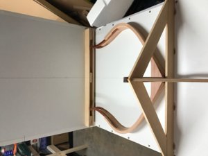
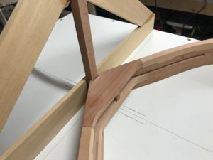
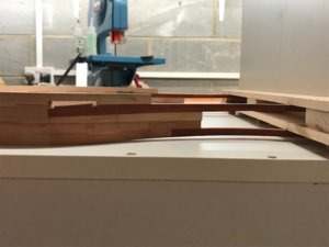
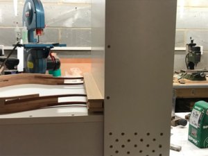
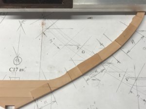
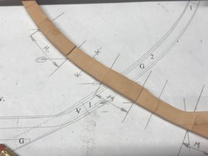
I have still got another weeks holiday before I go back to work and have had another productive day in the shipyard.I have been out and bought the material and constructed the jig to assemble the front bow "chunk".A total of seven frames will be joined together then removed and turned upside down and the remaining frames fitted.The jig is high enough to complete the bow section including the prow.
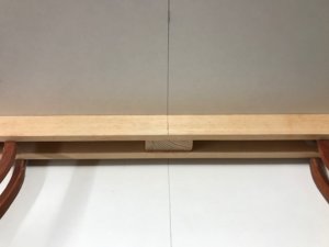
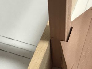
Other than the obvious factor that the jig is huge (will take a pic in the next batch including a Coke can for scale just to illustrate how big this section is)everything else is self explanatory.The dummy false keel follows the drag when the model is horizontal(the base of the keel slopes down towards the stern).The notches for this have been cut 1mm deeper than the plan hence the gap.This is intentional.The notches in the false keel piece will be shallower to compensate.I decided to leave a little more meat on the false keel as it is very thin where these notches are.The finished result will look exactly the same when assembled ;)

Kind Regards

Nigel

sp78.jpgsp79.jpgsp81.jpgsp80.jpgsp82.jpgsp83.jpg
 
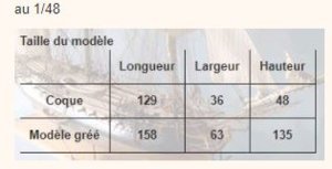
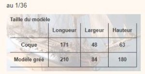
The Saint-Philippe is a really big ship, already a model in scale 1:48, but in 1:36 really huge
These are the dimensions which are mentioned on the web-page of ancre


bbb.JPG aaa.JPG

means the hull by itself is 1,71m long, 48cm wide and 63cm high.

So I am looking forward to see your jig to assemble the front bow "chunk".
We can hope, that you have very often holiday, so you have chance to work on your model and show us the updates.

@NMBROOK
HI Nigel, do you specifically select the individual frame parts on their color to create an even contrast over the complete build of the hull to show the frame construction details.
Fantastic work.

I agree here completely with Maarten, "painting with timber" of the mortice and tenon joints in order to see the frame construction is looking extremely good Thumbs-Up
 
Thankyou Gents for your very kind words:)

Yes Trident Model the construction of this vessel is very complex.I do feel that somethings appear more complex than they actually are though,I think Jean Bordriot's drawings are easier to understand than JC Lemineur's.Many of the sections are sliced through not where you expect them to be so a lot of cross referencing of different sheets is required to understand what you are looking at.There are also some errors where you have conflicting information on two or more views of the same area.
Regarding the tones of the Pear.I cut similar shaped items from one sheet to save material.This means I am working with two or three blanks at the same time which gives the variation in tone.There is some thought as to mixing up the tones but economical cutting results in this mix of colours.
Uwe,unfortuneately I do not get that many holidays:(I am back to work next Monday and have no more time off other than weekends until Xmas.I hope the new mill(which is in transit as I type this) shall speed the process of rebating the frames as I can take much wider cuts off.

Kind Regards

Nigel
 
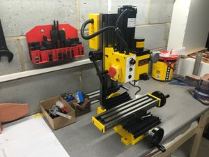
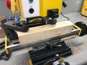
Ok then delivery man has been and I have spent the last few hours firstly tidying up the workshop and sorting the new mill ready for use.Removing the thick anti rust coating took an absolute age.At 56kg it ain't light and I certainly realised I am not 21 anymore lifting it onto the bench on my own.On the face of it,it is very well made,everything is solid metal,the pillar and table are all cast iron.
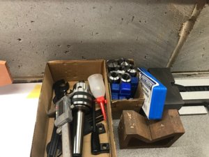
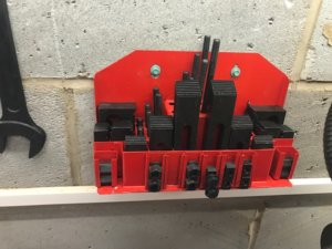
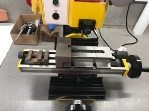
In addition I bought collets and cutters from 4mm to 16mm in 2mm increments,a step clamp set and are rather substantial vice which is designed specifically for this mill and features a quick adjustment function.
Just for a giggle I have put the Proxxon MF70 vise on the table for comparison to the new viseROTF
Don't get me wrong though,the MF70 will still come into it's own for doing small detail work when I need a cutter smaller than 4mm;)

Kind Regards

Nigel

sp84.jpgsp85.jpgsp86.jpgsp87.jpg
 
I am pleased with the mills performance.I have had to be careful on the Padauk though as it coarse grained and splintery.Breakout can occur due to the much lower RPM than the Proxxon.Fine cross grain work in Padauk may have to be done with the Proxxon but this is going to be on the fittings.
One other issue is that the cutter will only go down to within 50mm of the table.This is because I opted for collets that worked direct in the spindle's morse taper and tightened with the draw bolt.I could have gone for a milling chuck that would bring the cutter further down but they a 200 pounds!I have improvised with a timber pack(milled for even thickness) for now.Some pics of some more tenons this time cut with the new mill

Kind Regards

Nigel

sp88.jpgsp89.jpgsp90.jpg
 
Jim I wish I could say to you that you can keep it in a cupboard and get it out when needed.The instructions say you can mount it on a board so you can put it away for storage:rolleyes:Yeah right,I wouldn't want to lift it up and down when I needed it.it is staying bolted to the bench to avoid being on first name terms with the Chiropractor.
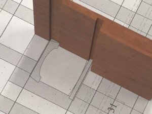
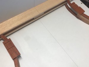
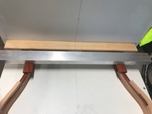
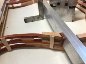
Moving on,whilst glue on the next frame is drying I addressed the side of the top gunport which is on the back of the last frame in the jig.I milled a profile from Paduak big enough to do the ports on both sides.You will notice the cill housings are modified slightly to the drawing.These are to enable easier mass production machining of the cills as these are not plain strips.
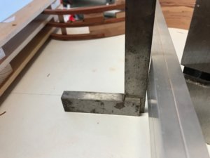
Finally the piece was split in half and the pieces epoxied to the back of the frame with the aid of an aluminium extrusion to ensure both in line and 92.25mm from the reference face.Provided I am vigilant with my measurements when setting all these pieces I should have a nice flowing line to the ports.
The overhangs will be trimmed back flush to the frame later on

Kind Regards

Nigel

sp91.jpgsp92.jpgsp93.JPGsp94.jpg
 
I have a similar Mill. It's a Seig X2, they're sold under a ton of brand names all over the world. You can use the drill chuck that came with it to hold the end mills. That will get you down to the table. I know real machinists will cringe but I've done it with brass, aluminum, and Acetal mostly out of laziness. I haven't done wood yet, but I'm sure it would work fine. For steel I definitely use collets because the shorter distance to the quill makes them much more rigid. Don't want to hijack your thread but there's a US company that makes a belt drive for it that increases the spindle speed by 1800 rpm. PM me if you'd like more info on that. I've done tons of mods on my mill.

Fantastic work on the model.
 
Thankyou Jim,what I would say though is that I am not infallible.Must have been having an "alpha"moment and glued the two gunport sides 8mm out of position,however it was exactly 8mm ROTF As I am using Epoxy,only option was to sand them down to nothing and clean the area up.Replacements remade and fitted in the CORRECT position:rolleyes:
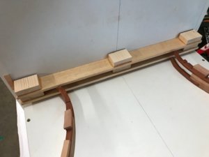
Moving forward I fitted the infills to frames in the jig overthickness and then sanded them down to the required thickness.This is a time consuming job but doing it like this minimises gaps.The third frame was continually trial fitted and total running thickness of the three frame assembly checked using the depth gauge on a digital Vernier.The keel chock was also fitted.Finally the third frame was bonded in place.You will notice I have cut through the back of the second frame to expose the gunport.I have started to Epoxy some temporary supports in place in readiness for cutting though the top frame into the gunports.

Kind Regards

Nigel

sp95.jpgsp96.jpgsp97.jpgsp98.jpgsp99.jpgsp100.jpg
 
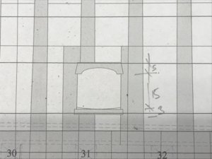
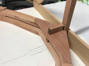
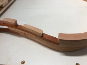
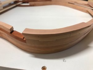
I have cut the main deck gunports out through the frames.When I milled the side of this gunport into the Paduak futtock I deliberately made the notches oversize.They should have been 4mm wide but my Paduak sheet was around 4.2mm so I made them 4.5.The bottom gunport cills piece through the spirketing and also the outer planking(not sure about that yet due to my timber choices).This means the cills have to be fitted later after the hull is faired.I wanted to make sure these would slide into place easily and would rather shim them than loose all the glue as the joint would be too tight.
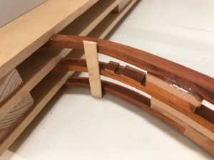
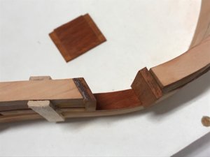
The pictures show the assemble process,I have to use 0.5mm Pear veneer to shim the head as when I had sanded the head to the required finish the thickness ended up being 4mm.The heads are epoxied in position using the Ali box to line everything through.Note the lean.The gunport slopes down 0.5mm across it's width in relation to the waterline.
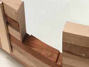
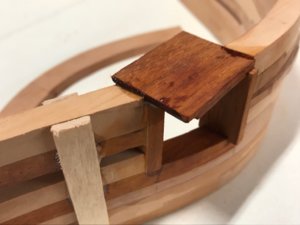
Once set the other gunport jamb is epoxied on top using a temporary spacer in place of the cill.It is left well oversize and will be profiled later.You will see that this slopes across the flat of the frame.This is because the port is on an angle as it is near the bow.This is why I had to pack the futtock to an angle to mill the face and slots.
The last picture is of the timber spacer that will sit across the gunport,its underneath notched to fit over the Paduak insert.

Kind Regards

Nigel

sp101.jpgsp102.jpgsp103.jpgsp104.jpgsp105.JPGsp106.jpg
 
Back
Top