• Win a Free Custom Engraved Brass Coin!!!
    As a way to introduce our brass coins to the community, we will raffle off a free coin during the month of August. Follow link ABOVE for instructions for entering.

School for Shipmodel Building School for model ship building

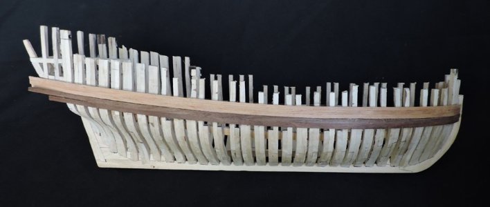
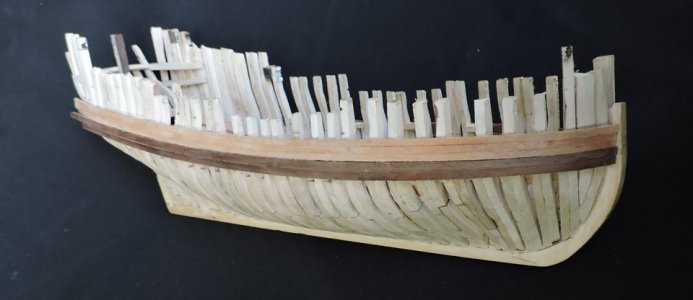
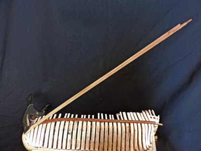
Building the bulwarks i am applying all 3 strakes at once to the hull starting at the bow.

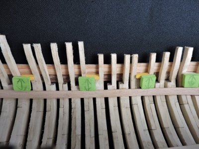
NOTE: you will see in these pictures i put the bulwark planks below the wales then took the pictures. After the picture set up i went back and added the planks. when i went back to check the pictures i noticed the error in setting up the photo shots. At that point it was too late to redo the pictures because i already glued the planks to the hull.
bulwarks4.jpg

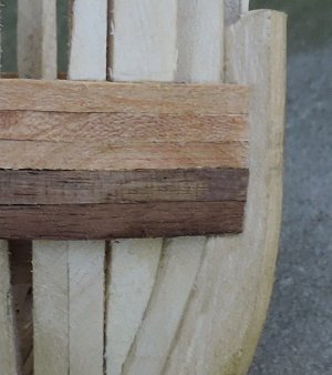
I like to glue the ends of the planks at the bow first to avoid and movement when clamping and maker sure everything is tight and even. Once the glue is dry then i will bend the planking. The planks are bent dry no soaking the planks or using heat the Cherry bent with no problem.

bulwarks.jpg
 
Last edited:
You can see i applied the bulwark planking in long strips rather than chop up the planking and applying it in pieces between the gun ports. My reasoning to do this is to make sure i maintain that sheer. It is easier to sweep one continues plank along the hull than to chop it up. The gun ports are open at the top so cutting the planking to the edge of each gun port is no problem.

Thinking ahead is a big part of model ship building. Those top timbers are prone to breaking especially if you are handling the hull while you're building. By adding the outside bulwark planks, it protects the top timbers. You see the wales and the bulwark planking just runs off the stern. There is a molding that goes at the stern and we will get to that later.

bulwarks6.jpgbulwarks7.jpg
 
This finishes the outside bulwarks except for cutting in the gun ports. The next time we meet in class there is a lot to talk about. The next step in the construction of a hull is the deck.
 
I like to glue the ends of the planks at the bow first to avoid and movement when clamping and maker sure everything is tight and even. Once the glue is dry then i will bend the planking. The planks are bent dry no soaking the planks or using heat the Cherry bent with no problem.
I like the idea of gluing the ends first, but when bending the planks as you go lower they are going to lift unless pre-shaped for the edge bend or are spiled planks.
I did a test piece with cherry and it lifts. This is assuming the planks breadth are reduced so they all land on the rabbet as they should, not like the pointy end planking many kits propose.
Allan
 
I like the idea of gluing the ends first, but when bending the planks as you go lower they are going to lift unless pre-shaped for the edge bend or are spiled planks.
I did a test piece with cherry and it lifts. This is assuming the planks breadth are reduced so they all land on the rabbet as they should, not like the pointy end planking many kits propose.


below the wales the planking is shaped and tested on the hull Spiled to fit. Once i have a fit and ready to glue to the hull then i will secure the ends against the stem or in a rabbit. Speaking of a rabbit years ago talking to a real boat builder he said they do not cut in a rabbit they are built in like this

rabbit.jpg


at the stem an example of no rabbit cut in

bul2.jpgbul3.jpg

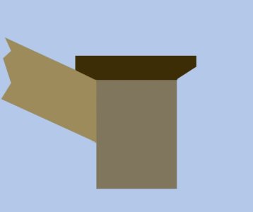
the planking butt against the stem and backed up by a heavy frame timber

knight1.jpg
 
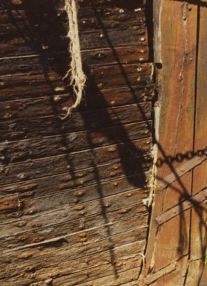
There are a variety of ways plank butts can land on a stem. A rabbet can be cut in the stem, which is frequently the case in smaller, lighter craft, or the plank ends can be fastened to the side of the stem and cut flush at the forward face of the stem and a cap piece installed over the "sandwich" of planks on either side of the stem. Alternately, a timber can be attached inboard of the stem with edges shaped to form a rabbet. The popularity of various options varies from vessel to vessel and period to period and depending upon whether the plank is carvel hung or lapstrake hung. Also, in determining the method to be used, consideration must be given to the most effective one for locating the stopwaters.
 
back in the day around the 1970s 1980s i use to hear from model builders "i used the standard ship building practices" now years later i realize there is no such thing as a "standard" each shipwright, shipyard, nation, time period, type of vessel all had different ways of building.
 
back in the day around the 1970s 1980s i use to hear from model builders "i used the standard ship building practices" now years later i realize there is no such thing as a "standard" each shipwright, shipyard, nation, time period, type of vessel all had different ways of building.

There's a lot of truth to the old shipbuilder's saying that, "Every boat is a collection of compromises."
 
The Deck

Sir William Burnaby was the commander and chief of the Jamaica station at Kingston. In his letter to the Admiralty, he requested the schooners to be built 100 tons each, to carry ten 4 pounders, and to draw feet 10 feet of water. If the Lordship approves of the vessels i propose they be built at New York or New England.

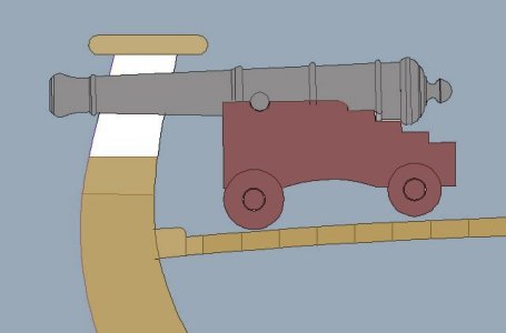
what is interesting with the request is the mention of the size of the cannons. I have noticed in contracts for armed ships they will include the size of the cannons the ship is to carry which suggest the cannons played a part in how the ship was built. Armed ships were not just built willy nilly and later the cannons were added. Let me show you why

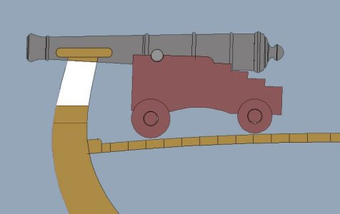
The Hawke was built to carry 4 pounder guns so if it was designed for the 4 pound cannons you could not change the cannons to say 9 pounders because they will not fit unless you rebuild the bulwarks and or lower the deck. The cannon is to big and hits the cap rail

Capture cannon5.JPG

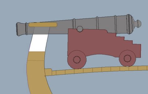
Even going up from a 4 to a 6 pounder you are faced with the same fit problem


Capture cannon4.JPG

The two schooners were built to carry 4 pound cannons and only 4 pound cannons

Capture cannon3.JPG
 
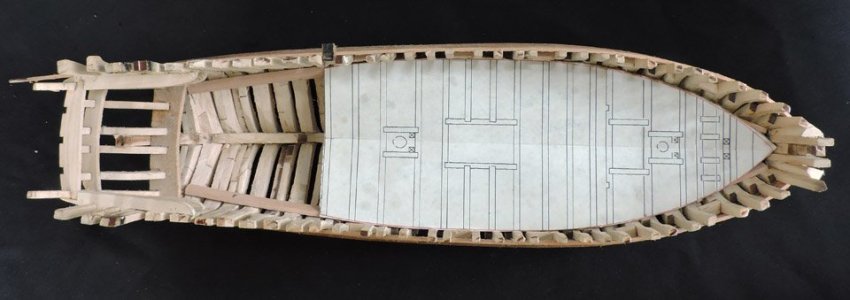
In an earlier class on installing the deck clamps spacer blocks were cut to the measurement from the top of the gun port sills to the top of the deck clamp. This is important measurement to get just right and to make sure the deck clamp is where it should be.

deck1.jpg

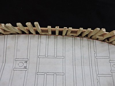
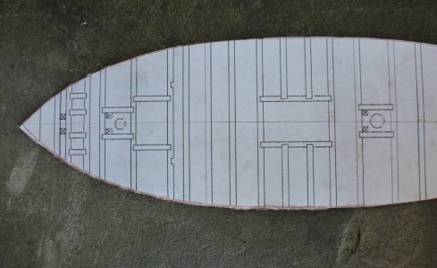
The first thing i did was to print out the main deck drawing then glue it to a piece of cardboard the type cereal boxes are made of. Then i cut out the shape and dropped it into the hull.


deck2.jpg

The deck drawing fit just about right to the hull except for a slight difference at the bow. i am not a purist and i will not rip out the bow to redo it. At this point in the build you are now building to the structure and not to the plans, so you make the deck fit the hull.

deck3.jpg
 
The following method for building the deck is to build it outside the hull which is so much easier than building the deck into the hull. Then drop in finished sections of the deck.

Sometimes you cannot build a deck outside the hull and you have to build it piece by piece in the hull. the reason is some hull shapes have a tumble home where the deck is wider than the distance between the cap rails so there is no way to drop a constructed deck into the hull.

005.JPG
 
ok now shop class

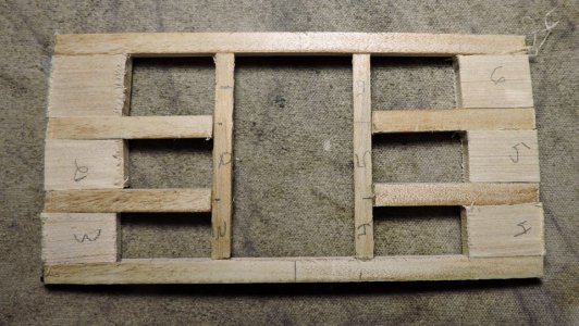
i first had to prep up the deck beams if you are building by hand then just rubber cement the deck pattern to a sheet of wood and cut out the beams. I laser cut the beams which some will say i took the easy way but what is the difference if i cut the beams with a scroll saw or laser both are power tools. Actually using the laser, you have to have a computer software to draw the beams and convert the drawing to a cutting file as opposed to just gluing a pattern to a piece of wood and start cutting away.
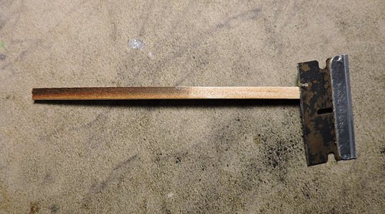
From time to time i come across discussions on removing the laser char and by doing that you are changing the size of the piece. What i did with the beams is to use a razor blade and scrape off the char.

deck4.jpg


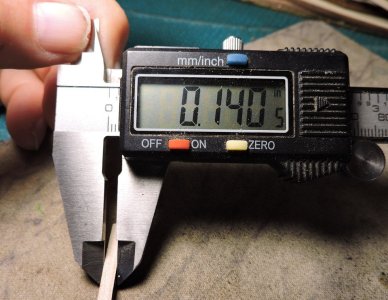
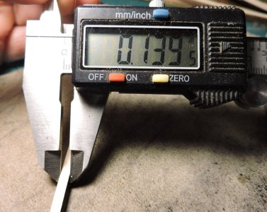
about changing the size of the piece is just not true i measured before and after i scraped off the char and it was a whopping one thousandth of an inch. if your concerned about that then good luck

deck5.jpgdeck6.jpg

now that the char is scraped off i lines up the beams and drew a line down the center. You need to know where center is because
of the camber which is (a measure of lateral main deck curvature in naval architecture). I cut the beams a little longer and all the same size so you have to work from the center out.

deck7.jpg
 
Using the printout of the deck as a template

deck8.jpg


setting up the first beam center mark on the beam to the center of the template the using a square block which can be anything that is square. i line up one side against the beam and the other edge to the outside of the carling

deck9.jpg

Now i can place the carling square to the beam, notice a piece of wood under the carling that is to raise the carling to match the top of the beam. Carlings are smaller than a beam.

deck10.jpg

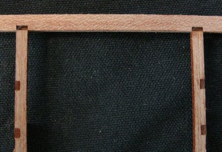
If you were paying attention to details you may of notice on the drawing the end of the carling is half way through the beam but the carling in the build butts against the side of the beam. what is going on here? am i cutting corners or got lazy? Yes the carling sits in a notch and on models i did go the extra mile to do the correct joinery. I did that because the model was not planked and built to show the joinery.
In this built that joinery will be covered up by the coamings so why bother to include it?

deck26.jpgnk10.jpg
 
Last edited:
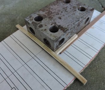
Both carlings are glued to the first beam and the next beam is set in place. Once again using a piece of wood to lift the carlings to match the upper edge of the beams.

deck11.jpg

Success of construction a deck is everything has to be exact and square.

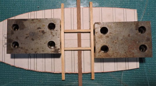
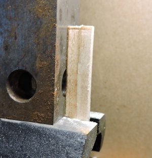
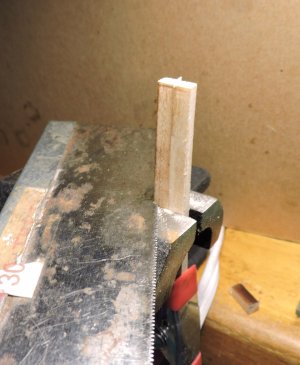
i like using a vice, i lined up two pieces of wood to the length of the carlings making sure they are square to the surface of the vice and cut then with a razor saw.


deck12.jpg

deck13.jpg

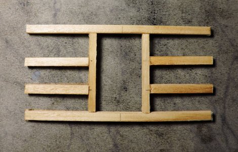
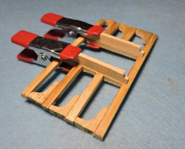
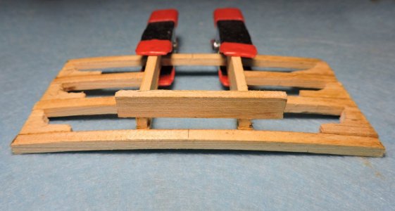
and final assembly

deck14.jpg
 
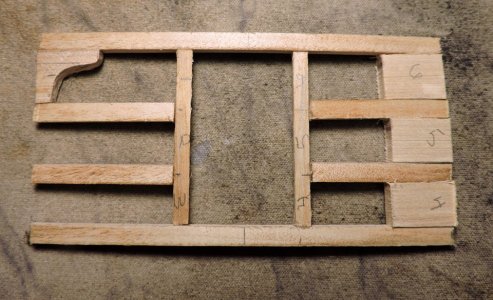
Next comes the lodging knees which start out as blocks fit between the beams

deck15.jpg

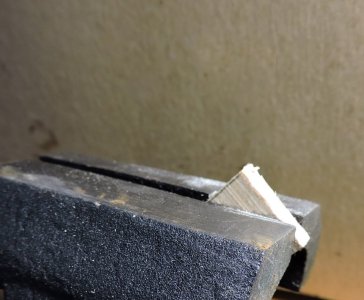
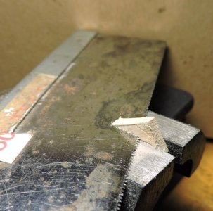
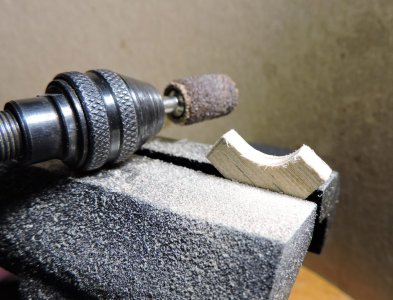
Each block is put in the vice and the corner is cut off


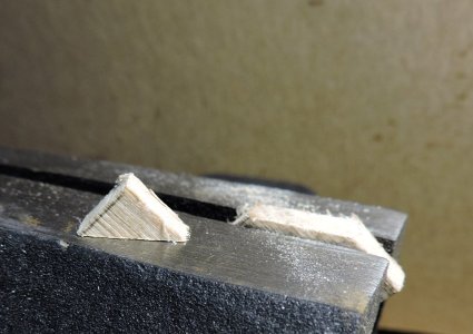
deck16.jpgdeck17.jpgdeck18.jpg

moving the wood up and using a Dremel the knee is shaped.

deck19.jpg

one done and 5 to go

deck20.jpg
 
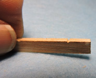
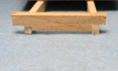
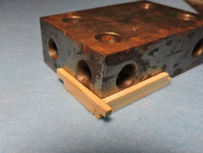
What is needed next are hatch coamings i cut two pieces so they are the length so the end at the center of the beans then cut notches in the ends

deck21.jpg

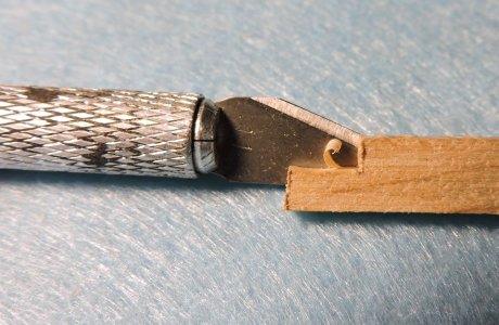
the end pieces are cut a little longer than the width of the hatch and i cut a mark at the inside edge. Then i cut a V so the saw blade falls in the notch
.

deck22.jpgdeck23.jpg

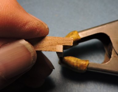
Fitting the end pieces is a matter of creeping up to the fitting of the notches. Here you see the gap between the bottom of the piece and the surface.

deck26.jpg

what it takes for that perfect fit is taking very thin cuts at a time

deck25.jpg

Until the fit is perfect, now you may hear you need a very hard wood to maintain sharp edges. This is Soft Maple and it works just fine.

deck24.jpg
 
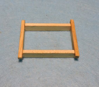
Time to assemble the hatch coamings again using a square in very important.

deck28.jpg

The ends are longer, and they are sanded to match the outside face of the sides

deck29.jpg

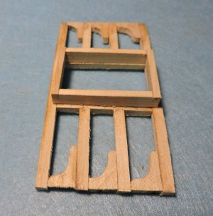
the finished coaming is now glued to the deck section

deck30.jpg


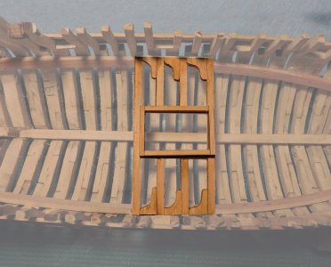
The finished section can be dropped into the hull sitting on the deck clamp

deck31.jpg
 
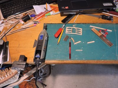
this ends todays class on the deck we do have a lot more to do so this will be continued. I would like to mention building the model does not require a mill or fancy tools. Looking at my work area all i have is a vice, a Dremel tool, razor blade and a knife a sanding stick and a razor saw.

deck32.jpg
 
Last edited:
Back
Top