-

Win a Free Custom Engraved Brass Coin!!!
As a way to introduce our brass coins to the community, we will raffle off a free coin during the month of August. Follow link ABOVE for instructions for entering.
-

PRE-ORDER SHIPS IN SCALE TODAY!
The beloved Ships in Scale Magazine is back and charting a new course for 2026!
Discover new skills, new techniques, and new inspirations in every issue.
NOTE THAT OUR FIRST ISSUE WILL BE JAN/FEB 2026
You are using an out of date browser. It may not display this or other websites correctly.
You should upgrade or use an alternative browser.
You should upgrade or use an alternative browser.
Steam powered wooden Drifter trawler, Formidable LT100, 1/20 scale by neptune
Hi John,View attachment 283527
the handles needed to be filed a little bit for a nice tight fit as in the top handle,
View attachment 283529
then they were tapped in place with a small light hammer, I then pulled them back out and applied a touch of CA glue and replaced them back in place,
View attachment 283531
all the handles in place,
View attachment 283533
and approx where they will sit on the fore deck,
View attachment 283534
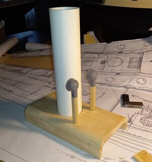
approx where the funnel will sit, it has of course to be trimmed to size yet,
thanks again for all the comments and the likes,
best regards John,
.
Fish hatches and lids look great.
Cheers,
Stephen.
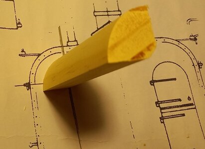
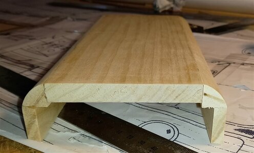
Next up is preparing for the superstructure, both the sides of the engine room and also the galley are rounded at the top, so I bought some wood quad of the right size for the Galley which was 22.5mm quad, the shortest length I could buy was 2.4m so I cut the amount needed for the top of the galley and then cut some of what was left down to the right size for the top of the engine room,
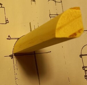
sitting over the plan, just the right size,
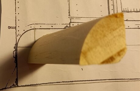
so I had to cut this quad down to 12mm to fit for the engine room top,
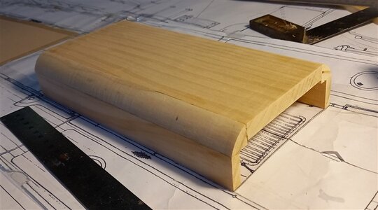
this is the base for the engine room structure, pretty straight forward construction,
and another view,
best regards John.
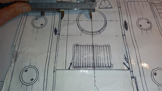
Just another warning about these plans, they look great but make sure you check everything, this is the top of the engine room, the vernier is measuring from the centre of the funnel to the outside of the casing, 60mm, the next line out from the vernier is the hand rail that runs along side the engine room casing,
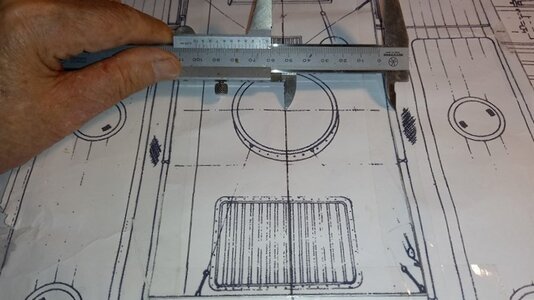
but when I measure the other side it is 60mm to the hand rail,
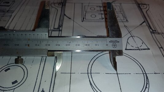
Here is a closer clearer look,
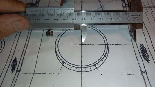
and the other side, so just be careful,
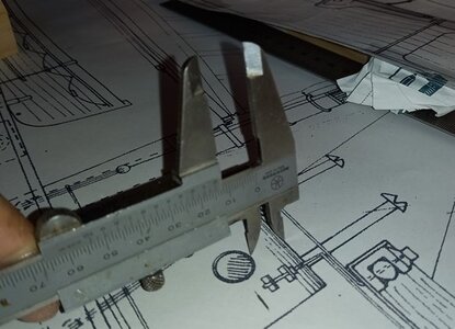
another thing that I noticed was the port hole for the galley, they show the top of the port 15mm below the galley roof line,
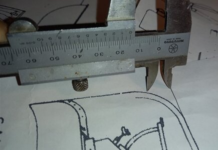
but 15mm down from the roof there is still a curve in the side wall, so I will have to lower the port to fit, there have been another few instances of these discrepancies,
.
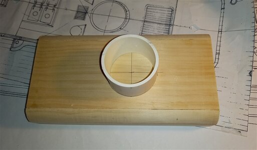
marking out for where the funnel will go,
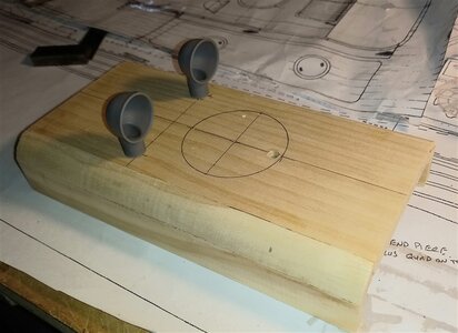
and also the two vents for the engine room,
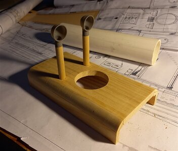
I made two supports for the vents, I'm not really happy with these as they are too small, so I may have to make a pair a bit bigger, and also cut the hole for the funnel,
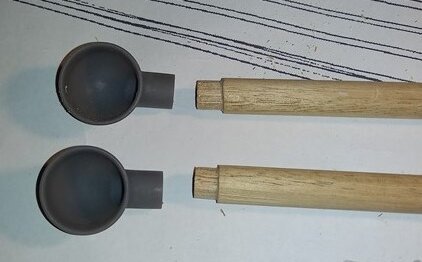
I just trimmed the tops of the dowells to allow the vents to slip on the supports,
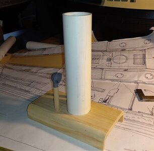
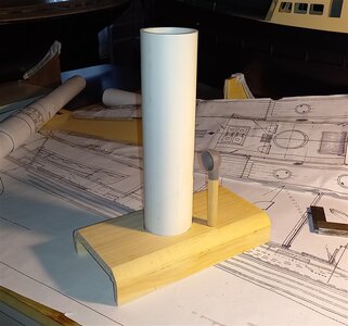
a few pics of the funnel and vents, I'm going to have to make some new vents these ones are just too small,
thank you for looking in,
best regards John.
Hi John,View attachment 283875
Just another warning about these plans, they look great but make sure you check everything, this is the top of the engine room, the vernier is measuring from the centre of the funnel to the outside of the casing, 60mm, the next line out from the vernier is the hand rail that runs along side the engine room casing,
View attachment 283876
but when I measure the other side it is 60mm to the hand rail,
View attachment 283877
Here is a closer clearer look,
View attachment 283878
and the other side, so just be careful,
View attachment 283879
another thing that I noticed was the port hole for the galley, they show the top of the port 15mm below the galley roof line,
View attachment 283881
but 15mm down from the roof there is still a curve in the side wall, so I will have to lower the port to fit, there have been another few instances of these discrepancies,
.
I agree the plans do leave you scratching your head and wondering.
Cheers,
Stephen.
Great idea with the quad John, lovely work.View attachment 283870
Next up is preparing for the superstructure, both the sides of the engine room and also the galley are rounded at the top, so I bought some wood quad of the right size for the Galley which was 22.5mm quad, the shortest length I could buy was 2.4m so I cut the amount needed for the top of the galley and then cut some of what was left down to the right size for the top of the engine room,
View attachment 283871
sitting over the plan, just the right size,
View attachment 283872
so I had to cut this quad down to 12mm to fit for the engine room top,
View attachment 283873
this is the base for the engine room structure, pretty straight forward construction,
View attachment 283874
and another view,
best regards John.
Cheers,
Stephen.
Love your woodworking, and many thanks for sharing the step-by-step tutorial.
Thank you Jim, I appreciate your comments and encouragement, thank you for following my build,
Best regards John,
Very ingenious way of making and fitting the handles, John. They look great!
Thank you Heinrich, on reflection maybe I should have used 1.2mm rod, but I am happy with them, thank you for following my build and also your encouragement,
Best regards John,
Great idea with the quad John, lovely work.
Cheers,
Stephen.
And also a big thank you to you Steve for all the support idea's and lovely photos of your LT100, you have helped me enormously, LT100 is a beautiful ship to build but there have and will be frustrations along the way, but that is all part of the journey and the fun of the build.
I hope you are feeling rested and relaxed I look forward to seeing you back at your LT100 soon,
Best regards John,
Thank you Brian for dropping in and viewing my LT100 and your supportive comments,Hello John, just catching up on your build log, and its coming along nicely.
best regards john,
Also a very big thank you to all those who are following my build and have left me likes, your support is fantastic, I am hoping that in the very near future I will have a chance to catch up on all your builds, at the moment thing's are a little bit hectic due to personal reasons and the builds keep me focused,
Best regards John
Best regards John
Thanks John,And also a big thank you to you Steve for all the support idea's and lovely photos of your LT100, you have helped me enormously, LT100 is a beautiful ship to build but there have and will be frustrations along the way, but that is all part of the journey and the fun of the build.
I hope you are feeling rested and relaxed I look forward to seeing you back at your LT100 soon,
Best regards John,
I have taken a bit of a side step and re-started work on my rope making and serving machine that was started over 30 years ago, i will post some info in the near future.
Cheers,
Stephen.
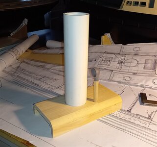
As I said in my last post I was not happy with the two vents, on checking the pics in the book and also the plans it was obvious that the vent itself wasn't too bad but the trunk needed to be thicker,
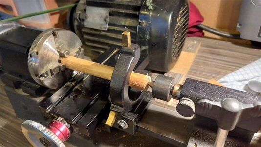
so I set up some thicker dowell in my sherline and centered it,
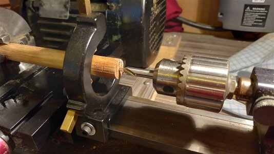
then center drilled it,
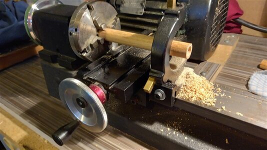
then drilled it out with a 10mm bit,
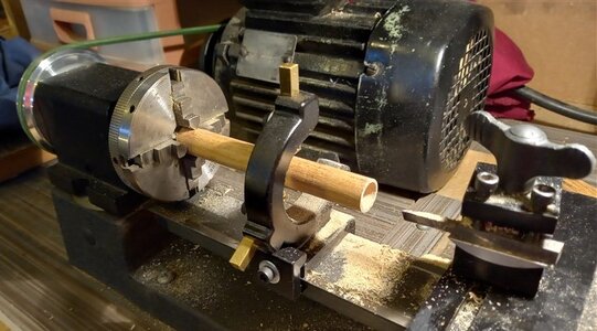
I needed the hole to be 12.5mm so I had to bore it out,
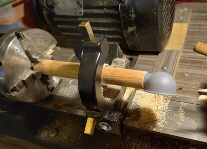
and the shaft of the vent fit just nice,
Continued in next post,
.
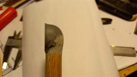
a little bit of filler to bridge the two parts, this was after I had CA glued the vents in place,
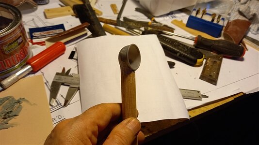
and a few pics while sanding it to shape,
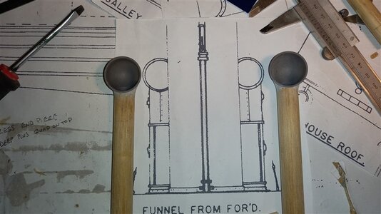
and next to the plan, I still have to attach the handles for turning the vents and also join where the trunk swivels,
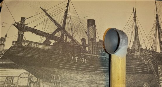
and compared against a drawing of the ship, not perfect but not too bad, on ce they have been painted they should look OK,
best regards John.
Great progress John,
I have also bought 3D printed cowls I will have to check how they look again, your vents look great.
Cheers,
Stephen.
I have also bought 3D printed cowls I will have to check how they look again, your vents look great.
Cheers,
Stephen.
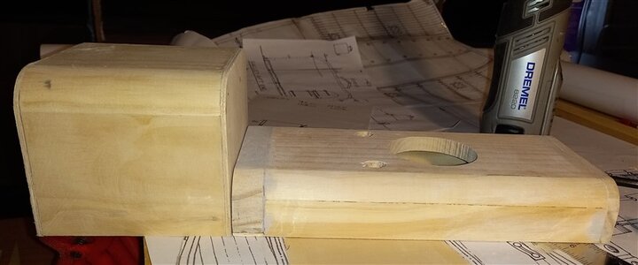
This is the carcass that will be the galley aft of the engine room casing,
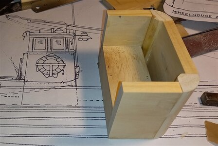
and this is the start of the wheel house,
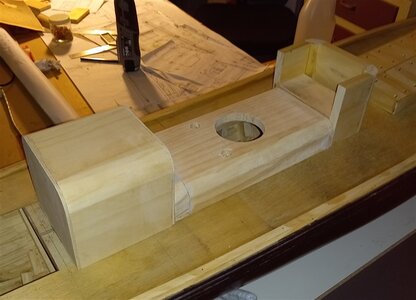
how the three will look when glued together,
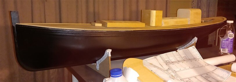
and a couple of pics of where it all will go,
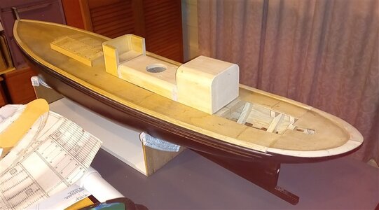
lots to do yet, and I have to decide whether I will just be painting the superstructure or plating it showing the rivets,
best regards john.
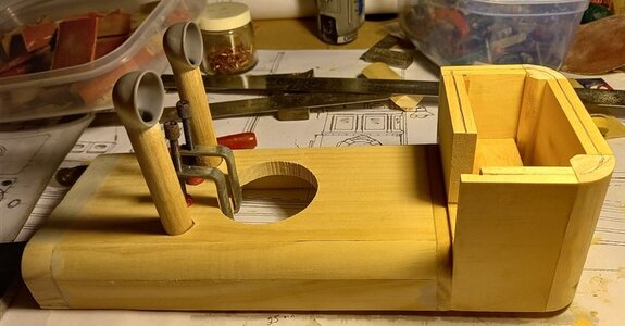
I've resized the holes for the trunk of the vents to go through and added reinforcing pieces under the engine room casing,
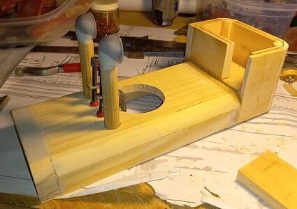
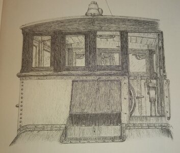
I've also added the back section to the wheel house, the wheel house up to where I am now is steel plating along with the engine room casing and the galley as well, the top part of the wheel house is timber and windows, see pic below,
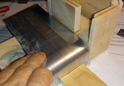
This is how I will do the steel plating showing the rivets, this is just a quick mock up,
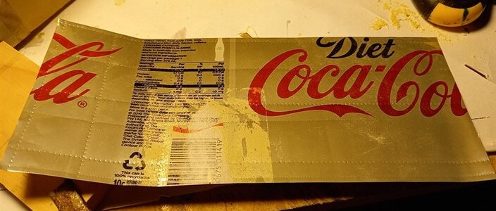
and this is what I used for the mock up,
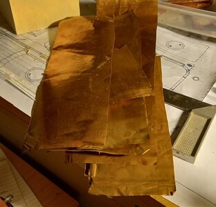
I will probably use these copper sheets that I have as long as i can smooth the sheets out so they look OK,
.
Hi John,
Great idea and progress, I was thinking of using thin card for simulating the plates, the old Coke can is probably an easier way.
Cheers,
Stephen.
Great idea and progress, I was thinking of using thin card for simulating the plates, the old Coke can is probably an easier way.
Cheers,
Stephen.


