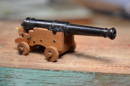
Not out of mind when you/we/I try to present things correctly and not pass over them. That is the frustration that I have with my small blackpowder muzzle loading ~6 inch cannon. The capsquares are just bent copper without a proper breach end hinge and muzzle end locking pin assembly which would withstand the large firing recoil. The small RH brass screws work but are not correct. Maybe I can with some effort and not the forming and solid soldering skill/equipment work something out between times on the range where I am working out the elevation bolsters and impacts at varying ranges. I need a large remote calm pond to see what the actual range is. The devil is in the details! Rich (PT-2)Thanks for noticing that Rich. The whole time I was creating those capstocks I was wondering if anyone would ever appreciate them!! And I still have 14 more to build. Yes they are complete. The actual cap squares are made of .018" brass. I machined 2 little pieces of scrap bronze into a stamp that I can use in a vice to squeeze a strip of .018" brass into the shape desired. The pins lying on top at the front and back of each cap are 22 gauge wire that I soldered in place with Stay-Brite solder. I kept the wire long until it was successfully soldered. Then cut it off and filed/sanded the final shape to the cap squares. the hinge is completed by bending the same 22 gauge wire into a tack shape. On the aft hinge side of the cap, there is only one hole needed to slip the tack over the pin and form the hinge -- pretty easy that one. The fore-locking mechanism is two holes rather than the proper slot. Here I drilled holes for a much narrower tack that could be a close fit for a thin metal key. Once everything was superglued in place, I squeezed a bit of wire and filed it into the L-shape of a retainer key and dipped it into a tiny bit of superglue before pressing it into the fore-lock.
You'll think you are out of your mind if you go to these extremes, but I think the result will make you grin.
View attachment 193235
-

Win a Free Custom Engraved Brass Coin!!!
As a way to introduce our brass coins to the community, we will raffle off a free coin during the month of August. Follow link ABOVE for instructions for entering.
-

PRE-ORDER SHIPS IN SCALE TODAY!
The beloved Ships in Scale Magazine is back and charting a new course for 2026!
Discover new skills, new techniques, and new inspirations in every issue.
NOTE THAT OUR FIRST ISSUE WILL BE JAN/FEB 2026
You are using an out of date browser. It may not display this or other websites correctly.
You should upgrade or use an alternative browser.
You should upgrade or use an alternative browser.
The Inspiration & Challenge that is "La Salamandre" 1:48
- Thread starter Jimmy
- Start date
- Watchers 31
-
- Tags
- 1:48 ancre la salamandre salamandre
Oh yes. . . your turning of the barrels is well detailed and executed. The challenge is a turned metal barrel of actual firing size is getting the trunions square and secure. That is partly explained in my copy of The Art of Ship Modeling. RichThanks for noticing that Rich. The whole time I was creating those capstocks I was wondering if anyone would ever appreciate them!! And I still have 14 more to build. Yes they are complete. The actual cap squares are made of .018" brass. I machined 2 little pieces of scrap bronze into a stamp that I can use in a vice to squeeze a strip of .018" brass into the shape desired. The pins lying on top at the front and back of each cap are 22 gauge wire that I soldered in place with Stay-Brite solder. I kept the wire long until it was successfully soldered. Then cut it off and filed/sanded the final shape to the cap squares. the hinge is completed by bending the same 22 gauge wire into a tack shape. On the aft hinge side of the cap, there is only one hole needed to slip the tack over the pin and form the hinge -- pretty easy that one. The fore-locking mechanism is two holes rather than the proper slot. Here I drilled holes for a much narrower tack that could be a close fit for a thin metal key. Once everything was superglued in place, I squeezed a bit of wire and filed it into the L-shape of a retainer key and dipped it into a tiny bit of superglue before pressing it into the fore-lock.
You'll think you are out of your mind if you go to these extremes, but I think the result will make you grin.
View attachment 193235
Thanks danielw! Those are very kind words, and much appreciated.
Thanks Ted. It's just one step at a time and lots of patience. Not to mention fun.
and fun we have (most of the time)Thanks Ted. It's just one step at a time and lots of patience. Not to mention fun.
Hallo @Jimmy
we wish you all the BEST and a HAPPY BIRTHDAY
Enjoy your day

Are you still working on the Salamandre? Would be great to see an update of your progress....
Thanks Uwek for the birthday wishes! It's now 4 pm, and I can truly say that today was a memorable and fun day.
I haven't quit on the Salamander. Will have much more time for it as winter approaches. But I do have some progress to share with the group when I can find time to organize the photos into a postable form.
I haven't quit on the Salamander. Will have much more time for it as winter approaches. But I do have some progress to share with the group when I can find time to organize the photos into a postable form.
After a year-and-a-half, I'm finally getting back to my build log on my La Salamandre model. Picking up exactly where I left off -- PT-2 (Rich) had asked for more detail regarding the capstocks/cap squares on these long guns. So I want to start out with a few photos and words that may help to explain how I produced those parts.
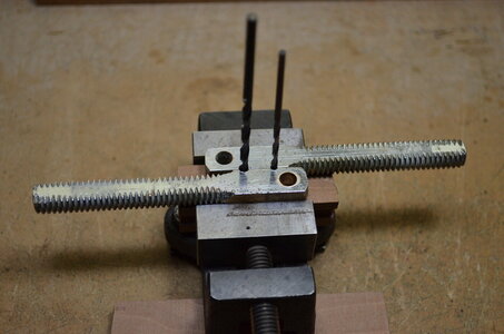
The following 2 photos show how I made a crude die for forming the arched part of the cap squares. NOTE: the difference between the radii of the 2 drills must be as close as possible to the actual thickness of the brass strip used to make the cap squares. The threads and the large hole in the 2 bronze pieces I used to make the die are of no consequence. These were just a couple of discarded bronze hold-downs from an old sailboat hatch I once had.
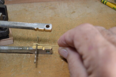
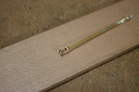
The rounding at each end of the cap square starts out as bits of brass wire bent into a staple shape and inserted into a piece of wood so that it holds the brass strip in the exact position for soldering. Look closely at the left end of the strip in this photo and you will just see the staple pressed into the wood and ready for solder. I used a low-temp - high silver content solder for this.
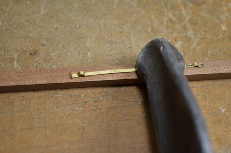
After soldering, it just needs the vertical parts of the staple to be ground or filed off, and the solder cleaned up with a file.
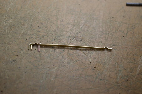
The cap square on the left end of the strip, along with its hinge U-bolt and fore lock & pin are ready to be cut from the strip, blackened, and installed.
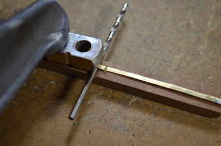
When soldering the rounding on the other end of the cap square, one needs a heat sink to avoid melting the other solder joint. This photo shows how I did that.
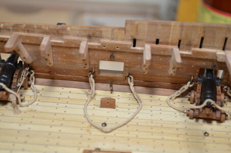
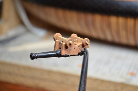
I spent quite a bit of time thinking about a way to mount the long guns that would allow me to install and remove them as many times as I might wish, until I was absolutely certain that they were ready for their final permanent installation. It needed to be invisible once the guns were in place, and very strong. The solution will hopefully be well explained by the following photos. In the first photo you see the 2 parts of the mounting system that are attached to the ship. Note the 1/16 inch brass pin with rounded end sticking out below the center gun port, and the odd-shaped little block fastened to the deck which has a small hole through it horizontally.
This photo shows the parts of the mounting system that are installed on the gun. The 1/16 inch hole in the forward axletree engages the brass pin below the gunport in the previous picture. And you can just see the small brass pin poking out of the front of the rear axletree which engages the small hole in the block of wood on the deck. The face of the rear axletree presses right up to the wood block, so all that is needed to make the mounting permanent is a bit of glue on each side of the smaller pin. Once the gun is fully rigged, none of these mounting elements are visible.

The following 2 photos show how I made a crude die for forming the arched part of the cap squares. NOTE: the difference between the radii of the 2 drills must be as close as possible to the actual thickness of the brass strip used to make the cap squares. The threads and the large hole in the 2 bronze pieces I used to make the die are of no consequence. These were just a couple of discarded bronze hold-downs from an old sailboat hatch I once had.


The rounding at each end of the cap square starts out as bits of brass wire bent into a staple shape and inserted into a piece of wood so that it holds the brass strip in the exact position for soldering. Look closely at the left end of the strip in this photo and you will just see the staple pressed into the wood and ready for solder. I used a low-temp - high silver content solder for this.

After soldering, it just needs the vertical parts of the staple to be ground or filed off, and the solder cleaned up with a file.

The cap square on the left end of the strip, along with its hinge U-bolt and fore lock & pin are ready to be cut from the strip, blackened, and installed.

When soldering the rounding on the other end of the cap square, one needs a heat sink to avoid melting the other solder joint. This photo shows how I did that.

I spent quite a bit of time thinking about a way to mount the long guns that would allow me to install and remove them as many times as I might wish, until I was absolutely certain that they were ready for their final permanent installation. It needed to be invisible once the guns were in place, and very strong. The solution will hopefully be well explained by the following photos. In the first photo you see the 2 parts of the mounting system that are attached to the ship. Note the 1/16 inch brass pin with rounded end sticking out below the center gun port, and the odd-shaped little block fastened to the deck which has a small hole through it horizontally.

This photo shows the parts of the mounting system that are installed on the gun. The 1/16 inch hole in the forward axletree engages the brass pin below the gunport in the previous picture. And you can just see the small brass pin poking out of the front of the rear axletree which engages the small hole in the block of wood on the deck. The face of the rear axletree presses right up to the wood block, so all that is needed to make the mounting permanent is a bit of glue on each side of the smaller pin. Once the gun is fully rigged, none of these mounting elements are visible.


GReat that you show us further progress on your Salamandre......After a year-and-a-half, I'm finally getting back to my build log on my La Salamandre model. Picking up exactly where I left off -- PT-2 (Rich) had asked for more detail regarding the capstocks/cap squares on these long guns. So I want to start out with a few photos and words that may help to explain how I produced those parts.
View attachment 303150
The following 2 photos show how I made a crude die for forming the arched part of the cap squares. NOTE: the difference between the radii of the 2 drills must be as close as possible to the actual thickness of the brass strip used to make the cap squares. The threads and the large hole in the 2 bronze pieces I used to make the die are of no consequence. These were just a couple of discarded bronze hold-downs from an old sailboat hatch I once had.
View attachment 303158
View attachment 303172
The rounding at each end of the cap square starts out as bits of brass wire bent into a staple shape and inserted into a piece of wood so that it holds the brass strip in the exact position for soldering. Look closely at the left end of the strip in this photo and you will just see the staple pressed into the wood and ready for solder. I used a low-temp - high silver content solder for this.
View attachment 303173
After soldering, it just needs the vertical parts of the staple to be ground or filed off, and the solder cleaned up with a file.
View attachment 303174
The cap square on the left end of the strip, along with its hinge U-bolt and fore lock & pin are ready to be cut from the strip, blackened, and installed.
View attachment 303178
When soldering the rounding on the other end of the cap square, one needs a heat sink to avoid melting the other solder joint. This photo shows how I did that.
View attachment 303179
I spent quite a bit of time thinking about a way to mount the long guns that would allow me to install and remove them as many times as I might wish, until I was absolutely certain that they were ready for their final permanent installation. It needed to be invisible once the guns were in place, and very strong. The solution will hopefully be well explained by the following photos. In the first photo you see the 2 parts of the mounting system that are attached to the ship. Note the 1/16 inch brass pin with rounded end sticking out below the center gun port, and the odd-shaped little block fastened to the deck which has a small hole through it horizontally.
View attachment 303181
This photo shows the parts of the mounting system that are installed on the gun. The 1/16 inch hole in the forward axletree engages the brass pin below the gunport in the previous picture. And you can just see the small brass pin poking out of the front of the rear axletree which engages the small hole in the block of wood on the deck. The face of the rear axletree presses right up to the wood block, so all that is needed to make the mounting permanent is a bit of glue on each side of the smaller pin. Once the gun is fully rigged, none of these mounting elements are visible.
View attachment 303182
View attachment 303183
Highly interesting photos showing your preparation of the metal works on the carriages.
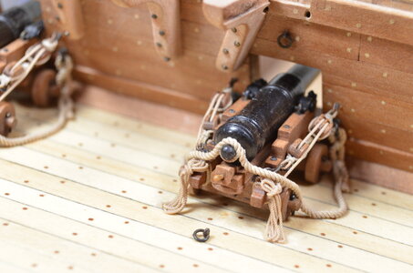
I love the photo of the finished tackled gun - with the rope ends not laying as a ring / sloop on the deck, but correctly hanging at the carriage
amazing details and accurate execution - a quality I would reach maybe in 1:8, but definitely not smaller
- Joined
- Apr 20, 2020
- Messages
- 6,239
- Points
- 738

excellent work, it's looks beautiful and accurateAfter a year-and-a-half, I'm finally getting back to my build log on my La Salamandre model. Picking up exactly where I left off -- PT-2 (Rich) had asked for more detail regarding the capstocks/cap squares on these long guns. So I want to start out with a few photos and words that may help to explain how I produced those parts.
View attachment 303150
The following 2 photos show how I made a crude die for forming the arched part of the cap squares. NOTE: the difference between the radii of the 2 drills must be as close as possible to the actual thickness of the brass strip used to make the cap squares. The threads and the large hole in the 2 bronze pieces I used to make the die are of no consequence. These were just a couple of discarded bronze hold-downs from an old sailboat hatch I once had.
View attachment 303158
View attachment 303172
The rounding at each end of the cap square starts out as bits of brass wire bent into a staple shape and inserted into a piece of wood so that it holds the brass strip in the exact position for soldering. Look closely at the left end of the strip in this photo and you will just see the staple pressed into the wood and ready for solder. I used a low-temp - high silver content solder for this.
View attachment 303173
After soldering, it just needs the vertical parts of the staple to be ground or filed off, and the solder cleaned up with a file.
View attachment 303174
The cap square on the left end of the strip, along with its hinge U-bolt and fore lock & pin are ready to be cut from the strip, blackened, and installed.
View attachment 303178
When soldering the rounding on the other end of the cap square, one needs a heat sink to avoid melting the other solder joint. This photo shows how I did that.
View attachment 303179
I spent quite a bit of time thinking about a way to mount the long guns that would allow me to install and remove them as many times as I might wish, until I was absolutely certain that they were ready for their final permanent installation. It needed to be invisible once the guns were in place, and very strong. The solution will hopefully be well explained by the following photos. In the first photo you see the 2 parts of the mounting system that are attached to the ship. Note the 1/16 inch brass pin with rounded end sticking out below the center gun port, and the odd-shaped little block fastened to the deck which has a small hole through it horizontally.
View attachment 303181
This photo shows the parts of the mounting system that are installed on the gun. The 1/16 inch hole in the forward axletree engages the brass pin below the gunport in the previous picture. And you can just see the small brass pin poking out of the front of the rear axletree which engages the small hole in the block of wood on the deck. The face of the rear axletree presses right up to the wood block, so all that is needed to make the mounting permanent is a bit of glue on each side of the smaller pin. Once the gun is fully rigged, none of these mounting elements are visible.
View attachment 303182
View attachment 303183
After a year-and-a-half, I'm finally getting back to my build log on my La Salamandre model. Picking up exactly where I left off -- PT-2 (Rich) had asked for more detail regarding the capstocks/cap squares on these long guns. So I want to start out with a few photos and words that may help to explain how I produced those parts.
View attachment 303150
The following 2 photos show how I made a crude die for forming the arched part of the cap squares. NOTE: the difference between the radii of the 2 drills must be as close as possible to the actual thickness of the brass strip used to make the cap squares. The threads and the large hole in the 2 bronze pieces I used to make the die are of no consequence. These were just a couple of discarded bronze hold-downs from an old sailboat hatch I once had.
View attachment 303158
View attachment 303172
The rounding at each end of the cap square starts out as bits of brass wire bent into a staple shape and inserted into a piece of wood so that it holds the brass strip in the exact position for soldering. Look closely at the left end of the strip in this photo and you will just see the staple pressed into the wood and ready for solder. I used a low-temp - high silver content solder for this.
View attachment 303173
After soldering, it just needs the vertical parts of the staple to be ground or filed off, and the solder cleaned up with a file.
View attachment 303174
The cap square on the left end of the strip, along with its hinge U-bolt and fore lock & pin are ready to be cut from the strip, blackened, and installed.
View attachment 303178
When soldering the rounding on the other end of the cap square, one needs a heat sink to avoid melting the other solder joint. This photo shows how I did that.
View attachment 303179
I spent quite a bit of time thinking about a way to mount the long guns that would allow me to install and remove them as many times as I might wish, until I was absolutely certain that they were ready for their final permanent installation. It needed to be invisible once the guns were in place, and very strong. The solution will hopefully be well explained by the following photos. In the first photo you see the 2 parts of the mounting system that are attached to the ship. Note the 1/16 inch brass pin with rounded end sticking out below the center gun port, and the odd-shaped little block fastened to the deck which has a small hole through it horizontally.
View attachment 303181
This photo shows the parts of the mounting system that are installed on the gun. The 1/16 inch hole in the forward axletree engages the brass pin below the gunport in the previous picture. And you can just see the small brass pin poking out of the front of the rear axletree which engages the small hole in the block of wood on the deck. The face of the rear axletree presses right up to the wood block, so all that is needed to make the mounting permanent is a bit of glue on each side of the smaller pin. Once the gun is fully rigged, none of these mounting elements are visible.
View attachment 303182
View attachment 303183
Lovely work, especially the gun caps
Ted
Thank you , dear Jimmy for a detail post and technology. My best regards, Alexander
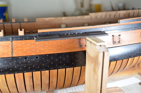
With the guns still removable, it's time to make and install the gun port lids. The port hinges were the most work. Basically the hinge parts were just tiny tubes and pins that were turned on the unimat. Then they were soldered to the straps using a similar arrangement to that used in making the cap squares for the guns. Also you will note that the ebony channels have been made and installed.
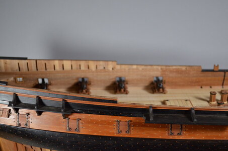
Proof that the lids do open, including the stern lids.
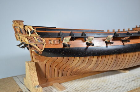
This simple jig was a great help for accurate positioning of the channels during glueing. The rectangular pieces laying on top of the channel are spacers for positioning the knees - which will be added as soon as this glue sets.
Salamander has only 6 knees per side under the quarter deck. Thankfully only one of them is canted. It's time to cut out some beams.
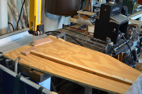
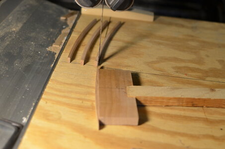
I show this way of making beams earlier in this build log, but for convenience, here it is again. Boudriot's drawing depict La Salamandre's beams as being circular rather than oval. Or they are so close to circular that I could not detect otherwise with my measuring equipment. These quarter deck beams have a shorter radius than the gun deck beams did.
At the right end of the wooden arm (it's hard to see in this photo) there is a row of precisely spaced holes and a steel pin protruding up through one of them. At the left you can see a batch of beams that have been cut by rotating the arm so as to pass a piece of pear wood through the blade and then advancing the arm by moving from hole to hole on the steel pin.
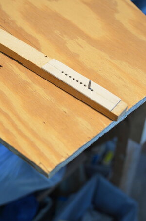
At this point, the pear wood has produced all the beams it can, so to get more, I would break off the last of it and glue on a new piece of pear.
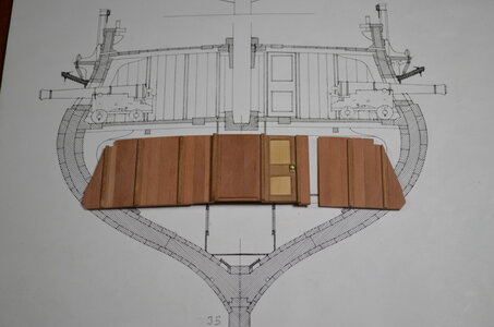
Another important structure needs to be installed with the beams. That's the removable great cabin bulkhead. I've been simply calling it the captain's wall.
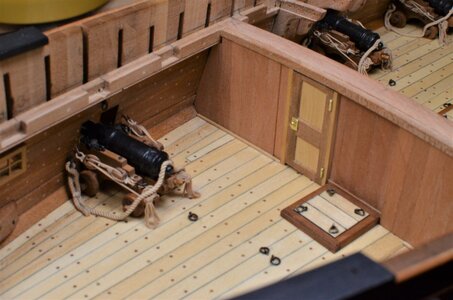
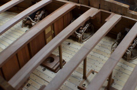
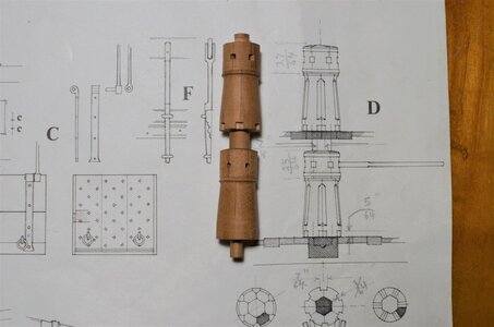
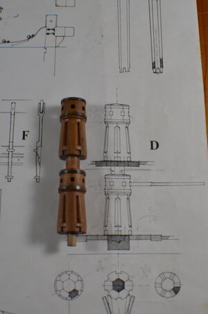
Another interesting project that goes with beam installations is the ship's windlass. I do wish I had taken more photos while building this.
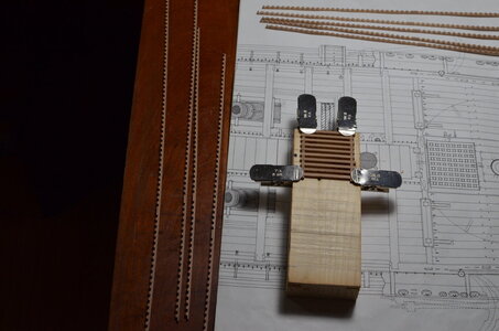
Also a good time to figure out the 2 gratings that will need to be framed up in conjunction with the quarter deck beam work. The wood block that the grating is clamped to is actually the same curvature as the deck. I use full half-lap joints in my gratings just because it makes them come out so nice and uniform.
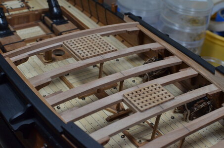
Trial fitting of gratings. Also note the completed cap rails and waterways port and starboard. None of these could be installed until the deck beams were in place.
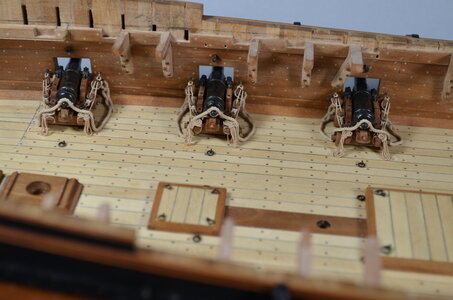
Now we can construct and install the chains. Is this fun or what? And finally we were able to tackle that cute little nautilus carving in ebony wood to the right on the cap rail. And as if that wasn't enough, we can now install the gun port lid tackles.
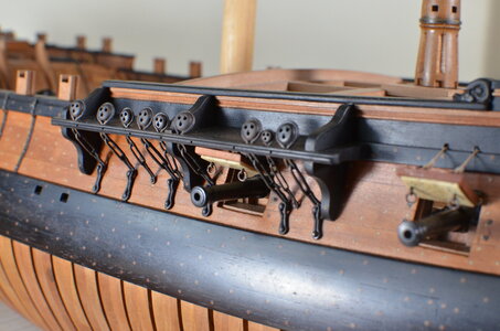
Here you can see the inboard elements of the gun port tackles.
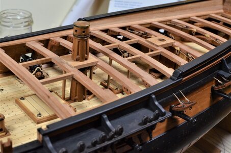
These riding bits have been in place for a long time, but I was playing with some camera lenses and got this great shot that really surprised me.
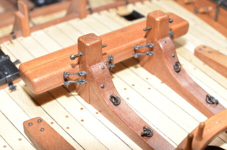

Proof that the lids do open, including the stern lids.

This simple jig was a great help for accurate positioning of the channels during glueing. The rectangular pieces laying on top of the channel are spacers for positioning the knees - which will be added as soon as this glue sets.

Salamander has only 6 knees per side under the quarter deck. Thankfully only one of them is canted. It's time to cut out some beams.

I show this way of making beams earlier in this build log, but for convenience, here it is again. Boudriot's drawing depict La Salamandre's beams as being circular rather than oval. Or they are so close to circular that I could not detect otherwise with my measuring equipment. These quarter deck beams have a shorter radius than the gun deck beams did.
At the right end of the wooden arm (it's hard to see in this photo) there is a row of precisely spaced holes and a steel pin protruding up through one of them. At the left you can see a batch of beams that have been cut by rotating the arm so as to pass a piece of pear wood through the blade and then advancing the arm by moving from hole to hole on the steel pin.


At this point, the pear wood has produced all the beams it can, so to get more, I would break off the last of it and glue on a new piece of pear.

Another important structure needs to be installed with the beams. That's the removable great cabin bulkhead. I've been simply calling it the captain's wall.


Another interesting project that goes with beam installations is the ship's windlass. I do wish I had taken more photos while building this.


Also a good time to figure out the 2 gratings that will need to be framed up in conjunction with the quarter deck beam work. The wood block that the grating is clamped to is actually the same curvature as the deck. I use full half-lap joints in my gratings just because it makes them come out so nice and uniform.

Trial fitting of gratings. Also note the completed cap rails and waterways port and starboard. None of these could be installed until the deck beams were in place.

Now we can construct and install the chains. Is this fun or what? And finally we were able to tackle that cute little nautilus carving in ebony wood to the right on the cap rail. And as if that wasn't enough, we can now install the gun port lid tackles.

Here you can see the inboard elements of the gun port tackles.

These riding bits have been in place for a long time, but I was playing with some camera lenses and got this great shot that really surprised me.

Last edited:
One of the best or maybe the best Salamandre I have every seen !
Very good work in all the details
I love the idea with the jig for curved cutting !!!!
Very good work in all the details
I love the idea with the jig for curved cutting !!!!
I can't believe I have missed this build log until today. HOW???
Wow what a project, perfectly executed, with so many images and techniques. Congratulations Jimmy.
I'm following now at this late stage.
Wow what a project, perfectly executed, with so many images and techniques. Congratulations Jimmy.
I'm following now at this late stage.
I can only agree Uwe, sensational work.One of the best or maybe the best Salamandre I have every seen !
Very good work in all the details
I love the idea with the jig for curved cutting !!!!
Hallo @JimmyWhen I was a youngster in the '50's, the old "James Bliss" catalog contained a kit to build a naval mortar. At the time I couldn't afford anything in that catalog, but that mortar, and the sailing ships that used it, absolutely intrigued me. So it seems odd that it has taken this long for me to finally build one. Certainly, the emergence of Boudriot and Berti's monograph and plan set had a lot to do with my decision to take on this project. I started building "Salamandre" in January of 2017. The scale is 1:48.
View attachment 137926
Before I even knew what ship I was going to build next, I had to cut down a pear tree in the corner of my yard where it was threatening my neighbor's fence. All I knew was that I wanted to build an admiralty board style ship (which I'd never done before), and that this pear wood should be be ideal for such a project. The logs were left to season for 2 years while I searched for a project to build. After initial seasoning, these photos show the first step of cutting up the logs into pieces. These pieces were then left to season for a few more months during which they underwent their final warping and twisting and became stable. Then I can just square them up and began slicing off finished model building timber as needed. I do my final processing of miniature lumber with a Proxxon table saw and a Jim Byrnes thickness sander.
View attachment 137929
View attachment 137930
This is 6 months into the build and all frames and the bow structure are built and have undergone initial fairing. The building jig is visible to the left. Somehow I did not retain any photos of the keel assembly and the associated stem and stern post. The little dowel pins in each frame where it meets the keel were my idea. obviously no one will ever see them in the model. However they provided absolute accuracy in the thwartship direction as I was constantly inserting and removing them during the initial assembly and construction work.
View attachment 137936
View attachment 137937
View attachment 137938
So here is a good look at the stern post and at least part of the keel. The carving of the rabbet is complete here.
View attachment 137942
One can finally see the shape of Salamander's bow at this point. I certainly wasted more than an hour or two admiring the shape of it. Oops! there is another ship in the background shadows here. I promise a full build log on that one in the near future.
View attachment 137948
The first piece of ebony wood was a thrill. Inboard, the gun deck clamps are in as well so the structure is becoming quite stable now. The little spacers that you see at the turn of the bilge are temporary.
View attachment 137961
Gun ports and stern timbers. Oh yeah !
View attachment 137962
View attachment 137963
View attachment 137964
View attachment 137965
View attachment 137966
View attachment 137967
View attachment 137968
View attachment 137969
View attachment 137970
View attachment 165836
View attachment 165837
View attachment 165835
View attachment 137971
we wish you all the Best and a HAPPY BIRTHDAY

Thanks for the birthday wish, Uwek -- and everyone!
With cooler weather on the way now, I expect to be having more time to spend working on Salamandre. And one of the best parts of that will be sharing the progress with all of you through additions to this build log. Any successful project requires some inspiration from time to time. My biggest source of inspiration, for this ship model, is all of you.
With cooler weather on the way now, I expect to be having more time to spend working on Salamandre. And one of the best parts of that will be sharing the progress with all of you through additions to this build log. Any successful project requires some inspiration from time to time. My biggest source of inspiration, for this ship model, is all of you.


