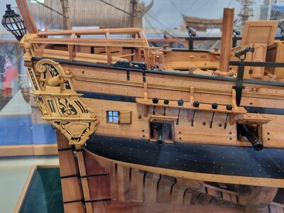
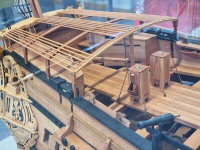
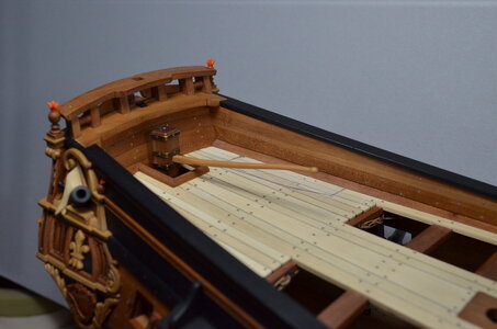
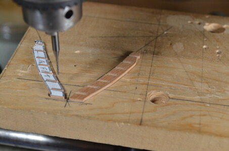
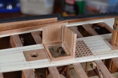
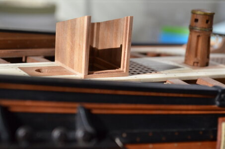
The Inspiration & Challenge that is "La Salamandre" 1:48

Hello to everyone! It's obviously winter time again in the northern hemisphere. No yard work. The full-sized boat is winterized. Too cold to leave the house unless I really must. So I have time to work on La Salamandre again!
My first thought (and second) was, give her a rudder. An interesting challenge, certainly. But not extremely worrisome.

DSC_0009 (5).JPG


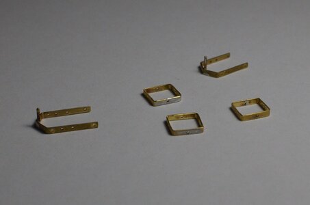
Simple rudder irons, gudgeons, and pintles. Brass strip, wire, and rod. Formed using simple hardwood jigs for uniformity. The strip was hand cut in order to get it this narrow. Everything silver soldered.

DSC_0007 (5).JPG


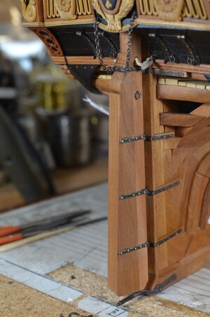
The snag protection device below the rudder was a fun little project all by itself!

DSC_0018 (5).JPG
 
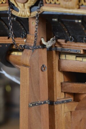
Closeup of finished rudder installation. Getting pretty busy here at the top of the rudder, but there will be even more hardware here when the emergency steering lines are installed.

DSC_0018 (6).JPG


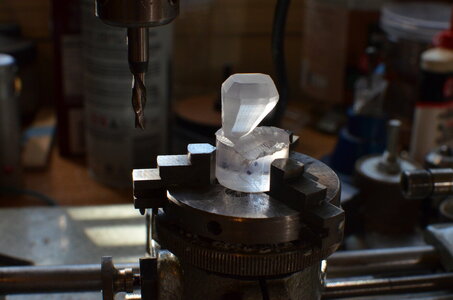
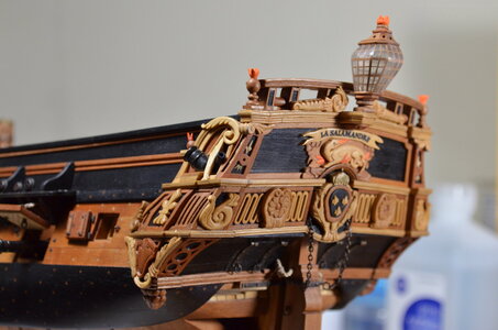
When I started this build a few years ago, I felt certain that one particular part of this ship was beyond my ability to scratch build. That was the stern lantern. There was just no way! So I've been searching on line for one, but was not really pleased with anything I found. I had some nice 3/4 inch diameter clear plastic rod stock, so I cut off a piece, set up the Unimat for vertical milling, with an indexing mount, and figured I would just see how far I could get. If this thing was a uniform crystal shape, I thought it would be difficult enough, but since it has to be skewed aft by about 14 degrees, I knew that I would soon prove what I already knew -- I won't be able to do this!

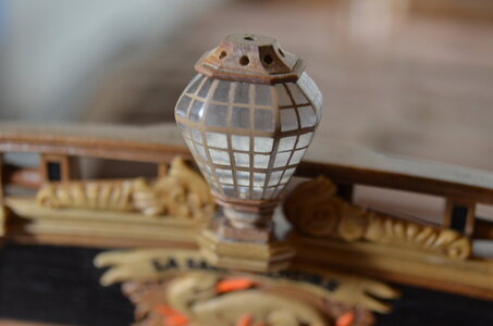
So I spent some long hours thinking, taking measurements off the several drawings of this light by Boudriot, and figured out how to cut a few faces of this crystal shape. But then I was stumped again. I repeated many times this process of thinking, measuring, calculating, and subsequently cutting another face or two. This went on for about 3 days. When I got to the result in the picture below, I was ecstatic! But I also realized that I had never even considered the challenge of creating the actual complex framework that seems to hold all of these window panes together. I understand that the original construction was probably a wood frame with mica windows. I found photos of HMS Victory's lanterns to be especially inspiring. But it took at least 2 more weeks of step-by-step processing to work out a way to accomplish it. The truth is I couldn't stop, but still felt quite certain that this piece would end up in the trash bin.

DSC_0011 (2).JPG


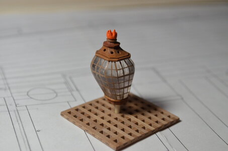
But here is the proof that sometimes it pays to just not quit, even if you don't know what you're doing! Now I will show you how I did it, but I truly hope that some of you will put me on to some much easier ways that this might be done.

By the way, those 2 ornamental carved bombs flanking the taffrail are also new additions to the model.

DSC_0002 (5).JPG


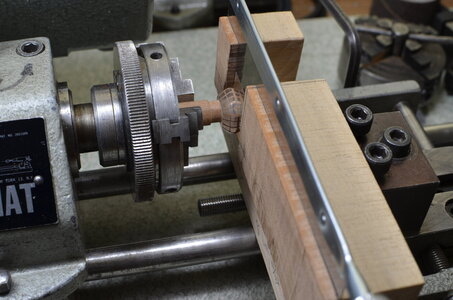
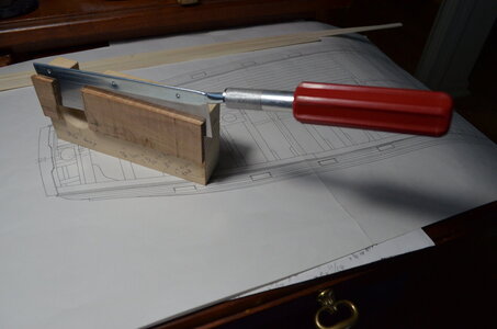
Hopefully, the next 3 photos will help the viewer to understand how this fixture I made for the Unimat is simply a guide for a common little handsaw that most of us use in our model making. The handle of the saw is just out of the photo at the bottom. The teeth of the saw are cutting accurate grooves in the plastic crystal. However, this setup can only cut the horizontal parts of the window frames. The chuck is rotated only by hand. No power is used at any time. The guiding fixture is attached to the lathe tool post so it can be accurately placed as needed to cut grooves for framing. A shallow groove is cut, and then the crystal is rotated 1/8 of a turn to the next face on the crystal where the groove is continued. And so it goes, face by face until the grove rejoins with itself. Then the fixture is moved to the next level of framing and process is repeated.

The tan color you see is actually paint which fills the grooves. It takes several coats. Scraping and very fine sanding subsequently removes the dried paint from the window panes, but strips of paint remain in the grooves, as you can see. This takes days to do, so I also was working on other things at the same time.

DSC_0024 (2).JPG


DSC_0002 (6).JPG


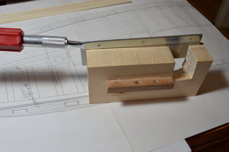
Here you can see how the fixture is secured in the basic block-style tool post of the lathe. Note the 2 indentations where the tool holder's screws have gripped the fixture.

DSC_0010 (3).JPG


Here the painted area has enough coats to fill its grooves. It's ready for scraping and sanding. If you are following this description closely, you will be wondering how I cut the vertical elements of the frame. Those were cut with nothing more than my less-than-ideal manual dexterity and a good pair of magnifying glasses.

DSC_0021 (2).JPG


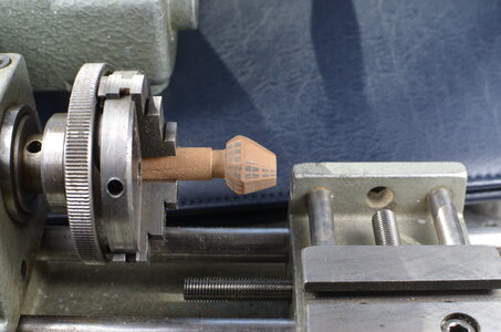
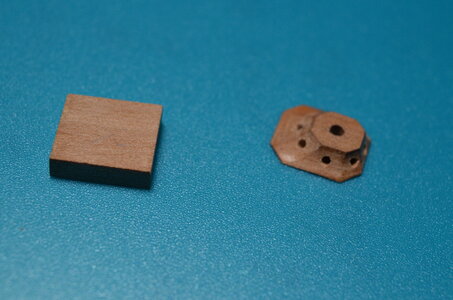
Part of the wooden top cap of the lantern. This is sort of a before-and-after view. This was done on the Unimat milling setup.

DSC_0028 (1).JPG


DSC_0032 (2).JPG


DSC_0009 (4).JPG


The main topsail sheet bits -- Was so focused on these that I forgot to take more photos.

DSC_0043 (2).JPG


DSC_0044 (2).JPG


Here I placed the 2 quarter deck breastwork panels just so I could take their picture. They have to wait for some decking to be laid before they can be permanently installed.

DSC_0045 (2).JPG


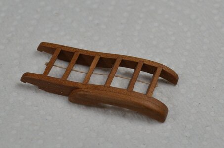
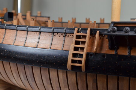
Anyone who has built this style of boarding ladder knows they are more challenging than they look.

DSC_0034 (3).JPG


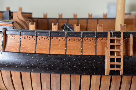
Ladder installed, and the u-bolts for tying down the midship coverings are being installed.

DSC_0035 (2).JPG


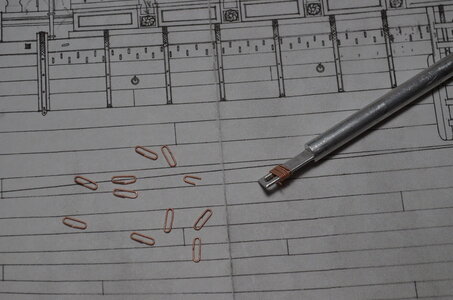
Making lots of u-bolts. Each loop makes 2.

DSC_0041 (1).JPG

DSC_0037 (2).JPG


The secret to making anything with repeatable uniformity is a good accurate jig. I made 3 of these before I got one good enough to use.

DSC_0040 (2).JPG
 
Closeup of finished rudder installation. Getting pretty busy here at the top of the rudder, but there will be even more hardware here when the emergency steering lines are installed.

View attachment 352043


When I started this build a few years ago, I felt certain that one particular part of this ship was beyond my ability to scratch build. That was the stern lantern. There was just no way! So I've been searching on line for one, but was not really pleased with anything I found. I had some nice 3/4 inch diameter clear plastic rod stock, so I cut off a piece, set up the Unimat for vertical milling, with an indexing mount, and figured I would just see how far I could get. If this thing was a uniform crystal shape, I thought it would be difficult enough, but since it has to be skewed aft by about 14 degrees, I knew that I would soon prove what I already knew -- I won't be able to do this!

So I spent some long hours thinking, taking measurements off the several drawings of this light by Boudriot, and figured out how to cut a few faces of this crystal shape. But then I was stumped again. I repeated many times this process of thinking, measuring, calculating, and subsequently cutting another face or two. This went on for about 3 days. When I got to the result in the picture below, I was ecstatic! But I also realized that I had never even considered the challenge of creating the actual complex framework that seems to hold all of these window panes together. I understand that the original construction was probably a wood frame with mica windows. I found photos of HMS Victory's lanterns to be especially inspiring. But it took at least 2 more weeks of step-by-step processing to work out a way to accomplish it. The truth is I couldn't stop, but still felt quite certain that this piece would end up in the trash bin.

View attachment 352044


But here is the proof that sometimes it pays to just not quit, even if you don't know what you're doing! Now I will show you how I did it, but I truly hope that some of you will put me on to some much easier ways that this might be done.

By the way, those 2 ornamental carved bombs flanking the taffrail are also new additions to the model.

View attachment 352045


Hopefully, the next 3 photos will help the viewer to understand how this fixture I made for the Unimat is simply a guide for a common little handsaw that most of us use in our model making. The handle of the saw is just out of the photo at the bottom. The teeth of the saw are cutting accurate grooves in the plastic crystal. However, this setup can only cut the horizontal parts of the window frames. The chuck is rotated only by hand. No power is used at any time. The guiding fixture is attached to the lathe tool post so it can be accurately placed as needed to cut grooves for framing. A shallow groove is cut, and then the crystal is rotated 1/8 of a turn to the next face on the crystal where the groove is continued. And so it goes, face by face until the grove rejoins with itself. Then the fixture is moved to the next level of framing and process is repeated.

The tan color you see is actually paint which fills the grooves. It takes several coats. Scraping and very fine sanding subsequently removes the dried paint from the window panes, but strips of paint remain in the grooves, as you can see. This takes days to do, so I also was working on other things at the same time.

View attachment 352046


View attachment 352049


Here you can see how the fixture is secured in the basic block-style tool post of the lathe. Note the 2 indentations where the tool holder's screws have gripped the fixture.

View attachment 352050


Here the painted area has enough coats to fill its grooves. It's ready for scraping and sanding. If you are following this description closely, you will be wondering how I cut the vertical elements of the frame. Those were cut with nothing more than my less-than-ideal manual dexterity and a good pair of magnifying glasses.

View attachment 352051


Part of the wooden top cap of the lantern. This is sort of a before-and-after view. This was done on the Unimat milling setup.

View attachment 352054


View attachment 352056


View attachment 352057


The main topsail sheet bits -- Was so focused on these that I forgot to take more photos.

View attachment 352058


View attachment 352060


Here I placed the 2 quarter deck breastwork panels just so I could take their picture. They have to wait for some decking to be laid before they can be permanently installed.

View attachment 352061


Anyone who has built this style of boarding ladder knows they are more challenging than they look.

View attachment 352062


Ladder installed, and the u-bolts for tying down the midship coverings are being installed.

View attachment 352068


Making lots of u-bolts. Each loop makes 2.

View attachment 352069

View attachment 352070


The secret to making anything with repeatable uniformity is a good accurate jig. I made 3 of these before I got one good enough to use.

View attachment 352075
Truly Amazing work, well done :) Thumbsup
 
Great work nad highest Quality - I am very happy, that it is outside winter and cold - so you are able to work and show us your progress
Hope, that the winter will stay ..... ;)
BTW: Are you sure that your model is in scale 1:48 - your accuracy looks more than 1:24
BRAVO, especialy for the metal works - BRAVO
 
Thank you so much - all of you! Those comments are powerful encouragement!

Here's a question someone will be able to answer:
I recently realized that the Salamandre's tiller is only about 18 inches above the deck at it's highest point (which is the tip). The helmsman would not be able to stand up to steer this vessel. In very light sailing conditions one might actually be able to sit flat on the deck with legs extended under the tiller, but in a wind gust you would need skid-proof pants, or something to brace your feet against, so you could put your back into the task.

Did they use ropes to control the tiller? I notice that the two snatch blocks on the cap rail (meant for controlling 2 stern anchors) just happen to line up exactly to port and starboard of the tip of the rudder.
I guess they fixed the tiller in a certain position with the help of a rope, but not used a rope for changing the position of the tiller / ruder.
For me the height of the tiller shown in the Boudriot drawings is too low. Often the tiller had a curved form upwards, in order to get the end point to a higher and more workable position.
Take a look at the Salamandre model of a german friend of mine (scale 1:24) - his tiller is higher compared to Boudriot

20220528_102601.jpg 20220528_102701.jpg

 
Thanks for digging into the tiller question, Uwe. The tip of that tiller is definitely higher than the Boudriot drawings. The drawings show the tiller only half as high as the binnacles, which are about 1 meter high. But your friend's tiller is almost as high as the binnacles. And that is a comfortable height for a standing helmsman.

Boudriot's work is awesome, but he does have his share of errors, too. I will continue to watch for more evidence that this is merely a drawing mistake. But, thanks to you, Uwe, I already know that I am going to raise my tiller higher when I make it.

By the way -- your friend builds a very nice ship model!

Thanks very much
Jimmy
 
Last edited:
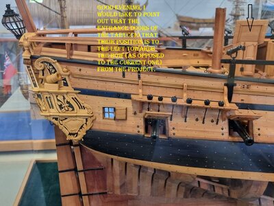
Good evening, I would like to point out that the entrance doors of the tabuccio that their position is to the left towards the bow (as opposed to the current one) from the project.

20220528_102601.jpg
 
Thanks for mentioning this, Frank. I have noticed that this feature seems to be oriented with it's door facing to port in some sources and to starboard in others. Is it possible that it was fitted both ways during the service life of La Salamandre?
 
Thanks for mentioning this, Frank. I have noticed that this feature seems to be oriented with it's door facing to port in some sources and to starboard in others. Is it possible that it was fitted both ways during the service life of La Salamandre?
Hello Jimmy, Thanks for answering me, the position that is planned is that position but, I don't think it should be repositioned differently, the sources are those of Maestro Boudriot.Frank
 
Good evening, I would like to point out that the entrance doors of the tabuccio that their position is to the left towards the bow (as opposed to the current one) from the project.

View attachment 352346
Sorry .... but it is correct on the model compared to the Boudriot drawings

Screenshot 2023-01-20 105203.png
(here Boudriot made a mistake with the hinches of the lid, which are on all other drawings on the outside and not like here in the inside)

Screenshot 2023-01-20 105221.png

Screenshot 2023-01-20 105447.png

Screenshot 2023-01-20 105515.png

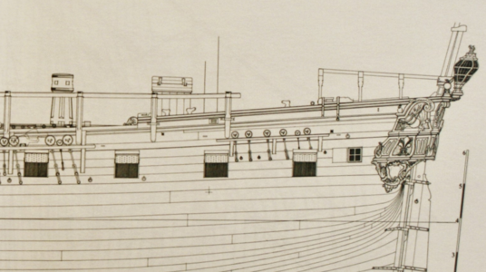
So Boudriot is showing the doors towards the right side looking towards the bow

Sorry @Jimmy to highjack your building log for this, but I think it is important to clarify
 
Sorry .... but it is correct on the model compared to the Boudriot drawings

View attachment 352469
(here Boudriot made a mistake with the hinches of the lid, which are on all other drawings on the outside and not like here in the inside)

View attachment 352470

View attachment 352471

View attachment 352472

So Boudriot is showing the doors towards the right side looking towards the bow

Sorry @Jimmy to highjack your building log for this, but I think it is important to clarify
for the position of the tab, the one on the model is exact, I did an informative research just to be coherent, there is something in the drawing
which is not clear, sorry for the mistake, Frank
 
Thank you, Walterone, for the "Wow" from Moscow!

And Uwe -- even though this is my build log, I very much appreciate that my post has stimulated this discussion about the orientation of the quarterdeck companionway doors. And I hadn't even noticed the discrepancy with the hinges! This kind of interaction benefits all of us. Thanks for starting it Frank!
 
So today is March 20th, which means that the winter of 2022-23 actually draws to a close today. And this seems like a good time to share my most recent progress on La Salamandre.

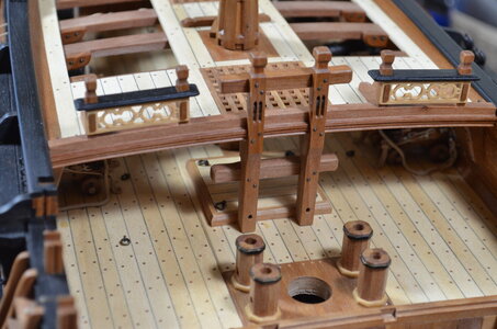
One of the most obvious features is the completion of the quarterdeck planking. Also the quarterdeck breastwork is permanently installed along with its supporting knees.

DSC_0001 (10).JPG


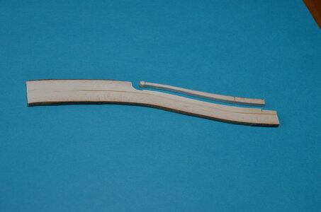
After our recent discussion about how high above the deck La Salamandre's tiller should be, I made an interesting discovery. Since the tiller fits into a square socket in the rudder head, it can be inserted in two different ways -- either curving upward or curving downward. Since the tiller has a slight "S" shape, it's easy to see that Uwe's friend installed his tiller curving upward, whereas Jean Boudriot drew the tiller curving downward. Next I noticed that some other model builders have also chosen to install their tillers in the much more practical elevated position.

When I began to consider what might be the best way to build this rudder at 1:48 scale, I first realized that it is an extremely skinny (therefore breakable) piece of wood. To simply saw it to the "S" shape out of a straight-grained piece of boxwood or pear would not have the best strength or appearance. I first considered soaking and bending, but also remembered that I had saved some pieces of a boxwood bush that we'd dug up in our yard a few years ago. Sure enough, I found a piece almost perfectly shaped and the picture below tells the whole story better than words can. Yes, that's wood bark on the edges.

DSC_0047 (1).JPG


Voila! The happy result. And again much thanks Uwe for helping to solve it's mysteries.

DSC_0055 (2).JPG
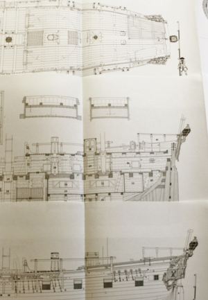

Here I am at an early stage of making the quarterdeck companionway ladder by milling slots in the ladder rails for the steps. I like this method especially since there is only one of these ladders to be made and the slots are supposed to stop before reaching the back of the rails. Gluing a photocopied pattern from the drawing to one rail establishes the accurate "S" shape and locates the step positions. The 2nd rail is simply traced from the 1st one. I attached a wooden surface to the milling table. Then I used a couple of tiny droplets of white carpenter's glue to fasten the rails onto the wooden surface at the correct angle (see pencil lines).

DSC_0014 (3).JPG


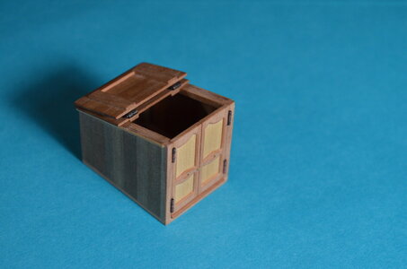
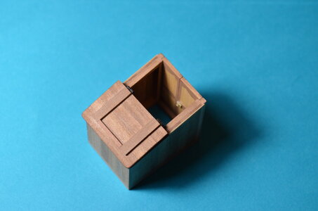
Here you can just make out the finished quarterdeck ladder down below the deck. And I have begun construction on the housing above deck which is referred to in the monograph as the "berthing or hood of the after ladder." At this point the hood can still be lifted off the model as I work on it. In fact I did not glue it in place until it was completely finished in every detail.

DSC_0018 (7).JPG


Close inspection here will reveal that both deck camber and sheer need to be accounted for if this hood is to be plumb and level with the keel as shown in the drawings. Left in this photo is aft, and right is forward. You can just see that the horizontal base timber below the hood doorway is slightly thinner in the aft direction. This may be more obvious in some other photos that will follow.

DSC_0022 (3).JPG


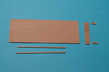
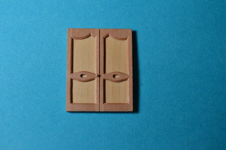
Now I'm getting into the construction of the doors for the after ladder hood (I'll refer to it as the companionway). To make these 2 perfectly symmetrical doors look good, many little parts must fit together snugly. I definitely spent some time thinking about how to make this easy to do, and I came up with the following:

The paneling on the doors consists of 10 pieces. There are 4 tall narrow vertical pieces and 6 short horizontal pieces. In each piece the direction of the wood grain should correspond to the direction of the piece itself. That's not in the drawings, it's just standard cabinetry! So I started with a 1/32 inch thick piece of pear wood. I cross-cut a piece off the end of it that was exactly the width of the 6 short horizontal panels. Hopefully the photo makes this clear there on the right side where 2 of the horizontals have already been cut out. At the bottom of the photo 2 pieces of narrow vertical paneling have also been ripped parallel to the grain from the same piece of pear wood.

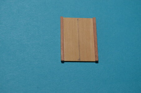
When you move through the next several photos, it should be obvious that the dimensions of all these pieces have to combine, when they are assembled together, so as to add up to the actual finished width of the two doors in their closed positions.

DSC_0029 (2).JPG


Here 2 of the vertical pear pieces have been glued to a boxwood panel. The boxwood is cut and squared to the exact dimensions I need for the finished pair of companionway doors.

DSC_0031 (2).JPG


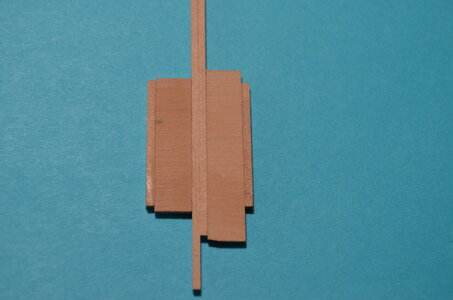
Here I am checking the fit of the inner pieces of pear from which all the inner panels will be cut. Keep in mind that only the left and right outer verticals are glued. The 2 inner verticals are identical widths, and the 2 horizontal grain pieces are also identical widths. There is enough extra stock that I can even afford to ruin a couple of horizontal panels in my efforts to make decent ones.

DSC_0032 (3).JPG


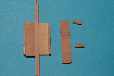
From here on I will assume that the process is fairly obvious. After all six little horizontal pieces are cut and glued in, I saved the 2 center verticals for the last gluing. That was important because I wanted them fit snugly but remain removable. That way they served to clamp the horizontals snugly against the outer verticals while gluing. But I could still remove the inner verticals at the end in order to sand their edges and give the appearance of a very slight but realistic gap between the doors when completed.

I fear I might be putting you guys to sleep with all this detail. So enough already! On to the final results.

DSC_0033 (3).JPG


The chamfer just takes lots of patience. Please don't look too close. Also, I did put these doors through the thickness sander some more to make the pearwood panels significantly thinner and closer to scale before completing the chamfering.

DSC_0041 (2).JPG

DSC_0046 (3).JPG


I used a straightedge and the back of a #11 blade to score the inner (imaginary) seam between the 2 doors.

DSC_0044 (3).JPG


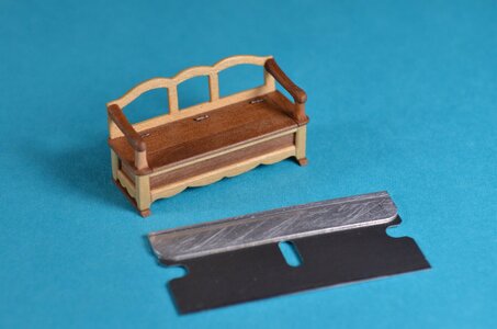
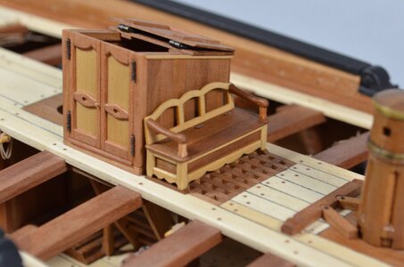
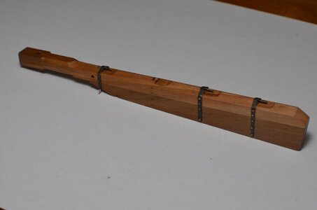
I decided to build just one more piece of deck furniture before submitting this report to you guys. However, I didn't anticipate that it would require almost an entire week to finish it. Unfortunately I don't think anyone will ever see the swords and pistols I put inside this small arms bench --- because I accidentally glued it shut!

only kidding of course.

DSC_0052 (2).JPG


There seems to be some controversy over whether the grating should be replaced with a standard hatch when this bench is placed forward of the companionway. The bench feet can get caught in the grating. I decided that the ventilation for the gun deck is more important, and therefore ordered the ship's carpenter to add skids to the feet of the bench. They are visible in both photos of the bench.

DSC_0053 (3).JPG
 
just beautiful - I love your "style"
Extraordinary quality

Maybe you showed us already once, how you make these little hinches - they are so realistic -
would be great if you can can show us the way and method your are making such hinches and how you install them
 
Maybe you showed us already once, how you make these little hinches - they are so realistic -
would be great if you can can show us the way and method your are making such hinches and how you install them
Okay. Let's see if I can explain it. Some of the hinges, like the ones on the gun ports and the ones on the flip-back companionway top on the quarter deck, are working hinges. I'll be making a few more of those for the doors on the deck sleeping cabins at the helm. I will take copious photos of those when I make them (hopefully soon). But right now I'll do a rough & fast demonstration of the really tiny simulated hinges that I made for the quarter deck companionway doors and the seat-lid of the small-arms bench.
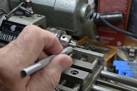
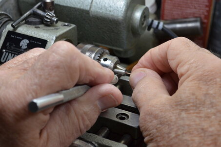
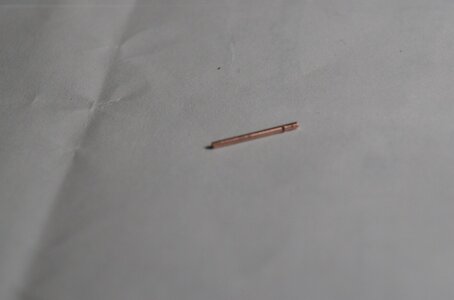
Below I am starting a hinge that will be less than 3mm wide when finished. I am using 20 gauge copper wire. I'm spinning it at a moderately high speed in my small lathe with a drill chuck mounted to the head stock. One could do this with other common tools. For example the Proxxon rotary tool mounted to the Proxxon universal bench mount would be great for this. Or any drill mounted in a vice might be workable.

Before mounting the selected piece of wire in your chuck, it needs to be rolled perfectly straight between to flat pieces of metal. Then I mount it in the chuck and spin it while pinching some very fine (maybe 400 grit) abrasive paper around it to thorough brighten the metal and remove any coatings from the wire.

Next, as shown in the photo below, I chuck the wire close to it's end (there is only 3 or 4 mm of wire in the chuck in this photo). I hold a very sharp #11 blade right against the end of the chuck while starting the motor. Normally with this first cut, I will press until I cut all the way through, and will have to grasp and hold the wire with my other hand so I don't lose it.

This gives me a perfectly trimmed and square end. Next I turn the piece of wire end-for-end in the chuck and position it so I can make my first partial cut (these are deep scratches really). For each scratch, I position the wire so I can place my blade against the tip of the chuck again. This prevents any wandering of the knife.


DSC_0001 (11).JPG


If you look closely you can see that I have cut one groove already and slid the piece out to where I can cut the next groove. This hinge will only require 2 such grooves. After this 2nd groove is cut, I will push the wire further into the chuck -- to the point where I can part off the excess wire with my blade.
Often I will make marks on the wire with a very fine marker (or whatever works) at the exact locations where I want the grooves and cut-off points to be.

The grooves might not be very noticeable at first, but after you put this hinge into your favorite blackening solution, the grooves will emerge darker than the rest of the piece.

DSC_0002 (8).JPG


I'm really putting this together fast and dirty! This picture below shows an overdone groove on the left and a pretty good one on the right. But I will go ahead and finish it. This is a good time to mention that all of these cuts and grooves need a touch with a very fine while spinning. That is partly what you see in this photo. The cut-off end to the right and the groove on the right have both been lightly filed. The left groove would look much better if it had gotten the file too.

DSC_0003 (10).JPG


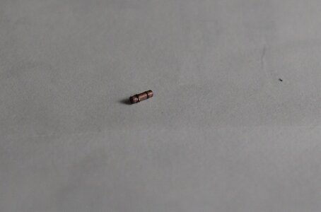
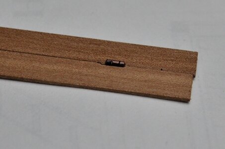
Now the hinge is cut off and has been given a quick blackening treatment (mostly rubbed off except in the grooves). The left groove and the left cut-off have not been filed -- you can see how important it is to do that. But notice how good and natural the right groove (and end) appears after some blackening. So I wouldn't put this one in my model, but my intention, of course, is for this to only be a helpful demo.

DSC_0004 (9).JPG


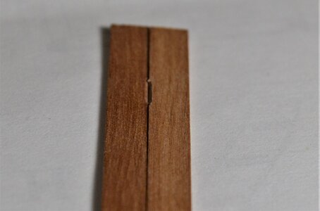
Next we must prepare the place where this hinge will live. Note that these are 2 separate pieces of wood. I used a swiss file to create a 45 degree chamfer on each piece. These are sloppy ones. To do this well a small blade or chisel is needed to provide this feature with sharp and square ends. It should not be longer than the hinge itself (this demo is not so great on either of these requirements.) If you're wondering how deep into the wood this feature should go -- the answer is "Not very." I like to see the hinge nesting in this little hammock only up to roughly 1/4 of it's diameter (maybe less).

DSC_0006 (8).JPG


A bit of CA glue is stroked into the wooden groove with a toothpick, and the hinge is dropped into the groove with a trusty pair of forceps. You don't want it to make that horrible {PING) sound at this point -- followed by a tiny click at the far end of the room. (and it's only 1/8 inch long!)

Just make sure its lined up nicely with the wooden parts and press it gently into place.

Now simply imagine that the groove in the wood on the left side is snug up against the hinge like it is on the right side. And if a file had been applied to the left end of the hinge before removing it from the chuck.

Fortunately these are pretty fast and cheap to make. An hour or two spent practicing should produce results you'll be completely proud of.

Now I'm thinking about some of you guys out there who have carried this process to levels I haven't even imagined yet...................................

DSC_0008 (10).JPG
 
Back
Top