• Ships of Scale has incorportated an extra level of security when you log In. Please follow on-screen prompts to acknowledge that you are not a robot via a "Check Box" or a "Pictorial Check Box Puzzle". This is needed due to higher level of AI Activity Security.
  • SUBSCRIBE TO SHIPS IN SCALE TODAY!

    The beloved Ships in Scale Magazine is back and charting a new course for 2026!
    Discover new skills, new techniques, and new inspirations in every issue.

    NOTE THAT OUR NEXT ISSUE WILL BE July/August 2026
  • Win a Free Custom Engraved Brass Coin!!!
    As a way to introduce our brass coins to the community, we will raffle off a free coin during the month of August. Follow link ABOVE for instructions for entering.

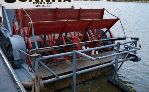
The Juanita Sternwheeler 1/24

The Pilot House Console​

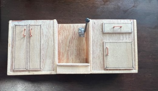
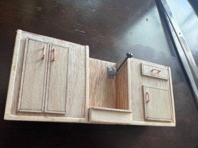
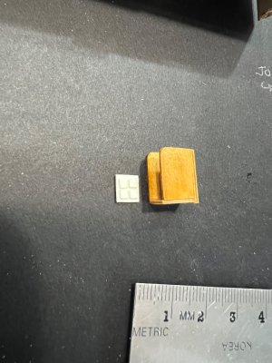
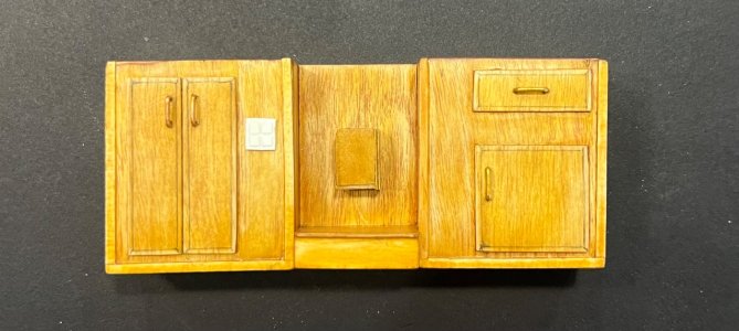
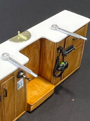
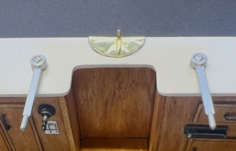
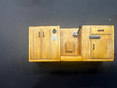
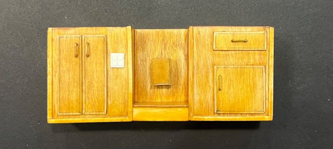
This tiny 4¼-inch-wide console has been the most detailed scratch-built assembly of the entire Juanita project. The challenge was not the woodworking—it was the research. As far as I have been able to determine, there is only one photograph of the actual Juanita pilot house console available on the internet, and it was taken from an angle that hides many of the details.

Recreating it became a true detective project. By enlarging the original photograph, studying every shadow, comparing it with modern towboat controls, and using AI to help interpret hidden details, I slowly pieced together what the console must have looked like. Every handle, cabinet door, switch, and fitting had to be designed and fabricated from scratch.

Construction Sequence​

  • Studied the only known reference photo of the real Juanita console, enlarging it repeatedly to identify every visible feature.
  • Designed the cabinet layoutbased on proportions visible in the photograph, including:
    • Port storage cabinet with double doors.
    • Starboard drawer and lower cabinet.
    • Center opening for the operator.
    • Raised footrest beneath the center opening.
  • Scratch-built the entire cabinet from basswood sheet and strip stock.
  • Added individually framed doors and drawer fronts to duplicate the recessed panel construction of the original.
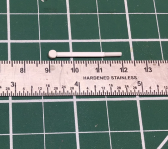
  • Installed handmade copper wire door pulls bent to identical shapes.
  • Built the center document holder mounted on the rear panel.
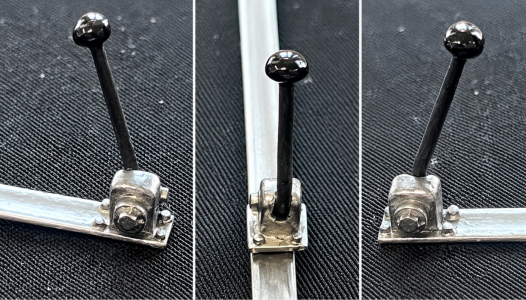
  • Designed and fabricated the throttle control assembly, including:
    • Cast-looking mounting block.
    • Pivot housing.
    • Four simulated mounting bolts.
    • Pivot bolt detail.
    • Black control lever.
    • Rounded control knob.
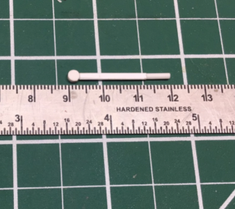
  • Scratch-built both steering tiller arms, carefully shaping them to match the profile seen in the original photograph.
  • Finished the steering arms in aluminum with weathered metallic highlights.
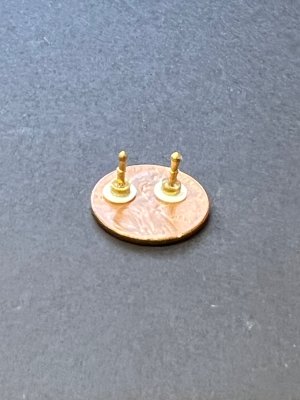
  • Turned two miniature brass control knobs for the compass compensator using brass fittings, then mounted them on insulating white bases exactly like the prototype.
  • Fabricated the brass compass compensator plate, polishing it to a mirror finish before installation.
  • Installed the electrical switch panel, reproducing the four-button appearance visible in the reference photograph.
  • Added the ignition/key switch on the port side of the console.
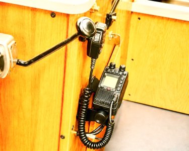
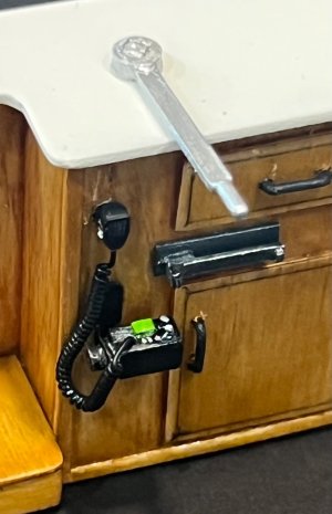
  • Built and installed the VHF radio microphone cradle, then added:
    • Hand microphone.
    • Coiled microphone cord.
    • Radio mounting bracket.
  • Applied multiple coats of wood stain and clear finish to reproduce the warm varnished appearance of the real pilot house cabinetry.
  • Performed repeated test fitting of every individual component before permanent installation to ensure proper spacing and alignment.

Details Worth Mentioning​

  • The throttle quadrant alone required several separate miniature parts and went through multiple redesigns before I was satisfied with its appearance.
  • The brass compensator assembly was made almost entirely from modified brass hardware, proving once again that ordinary materials can become convincing scale fittings with a little imagination.
  • The radio microphone and its coiled cord add a surprising amount of realism despite being only a few millimeters in size.
  • Every cabinet handle was bent individually from fine copper wire.

Final Thoughts​

Although this console measures only 4¼ inches (108 mm) wide, it contains dozens of individually fabricated parts. It became one of those projects where every evening's work produced only a few additional details, yet each one brought the model closer to the character of the real Juanita.

Looking back, this little console perfectly captures what this build has become: not simply assembling a kit, but researching, interpreting, and recreating a vessel for which very little documentation exists. Sometimes the smallest assemblies demand the greatest amount of patience, and in this case, the effort was well worth it.

Only thing missing are the gauges and Gravman is helping me creating this tiny wonders.

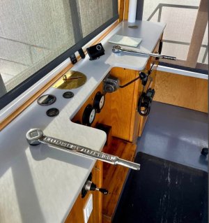
REAL JUANITA CONSOLE
1.jpg

2.jpeg

4.jpeg

1A.jpeg

9.jpeg

5.png

7.jpeg
8.jpeg


REAL VHF RADIO
12.jpeg

SCRATCH BUILT RADIO

13.jpeg


16.jpeg

14.png

15.png

16.jpeg

11.jpeg

8.jpeg

14.png
 
Fantastic detailing, Julian! Your build is truly going to be a work of art.

View attachment 625854


Thank you, Herrmill! I really appreciate your kind words and encouragement. I’ve been putting a lot of time and love into the Juanita, so hearing that you think she’s becoming a work of art means a lot to me. There’s still plenty of detailing to come!

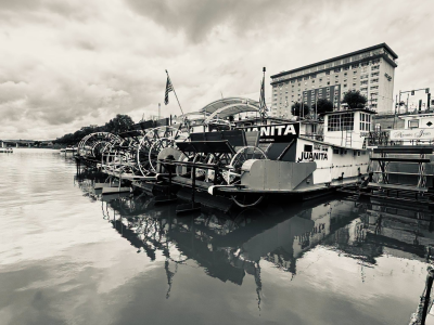
And thank you as well for the beautiful B&W picture of the Juanita. That one will definitely be added to my collection. It’s a wonderful addition!
 
The historic city of Marietta, Ohio sits at milepost 187 on the Ohio, River. It is by Midwest USA standards very old, established in 1788. Every September the city holds its annual Sternwheeler Festival. This year it will be held over the weekend of September 14-16. This will be the festival’s 50th anniversary. I was there for the first but moved away later so don’t know the details of this year’s celebration.

Typically, the event features a lineup of small sternwheel wheel boats like Juanita moored along Marietta’s levy and a spectacular fireworks display over the Ohio River. Marietta’s own sternwheeler, the Valley Gem is also featuring trips through the hand operated locks on the Muskingum River.

I wonder if your sternwheeler Juanita will be attending.

Roger
 

Scratch-Building the Juanita's Miniature Brass Steering Sheaves​

By John ("Gravman")​

Build log written by Julian Nodarse

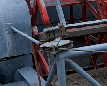
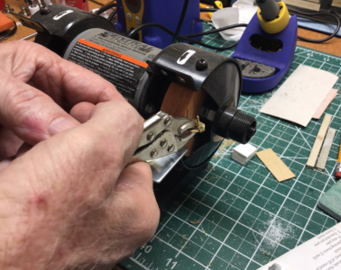
One of the features that immediately caught our attention on the stern of the Juanita was the pair of steering sheaves used to guide the steering cables for the monkey rudders. Although they are very small components on the real vessel, they are highly visible on the finished model.

Rather than simplify them, my good friend John (Gravman) decided to reproduce them almost exactly as they appear on the full-size boat.

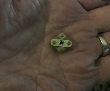
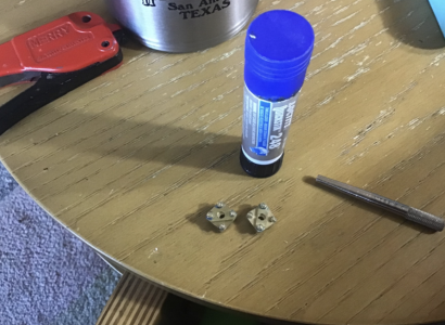
The result is a pair of miniature brass sheaves that are truly little pieces of jewelry.

Studying the Prototype​

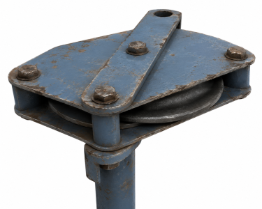
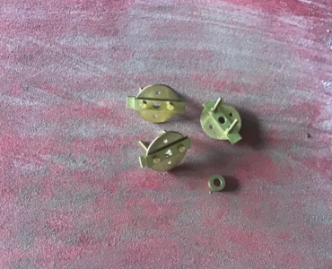
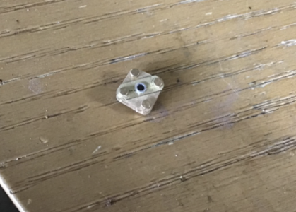
Everything began with careful study of the original fitting. Close-up photographs revealed that these were not ordinary pulleys but fabricated steel assemblies consisting of two side plates separated by four spacers with a grooved sheave mounted between them.

The challenge wasn't simply making something that looked similar—it was reproducing the construction in miniature.

Designing the Parts​

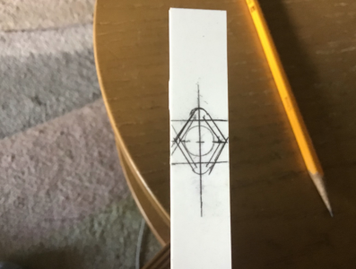
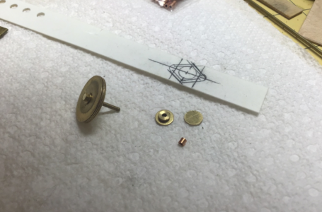
John first sketched the outline directly onto styrene to establish the exact geometry of the side plates.

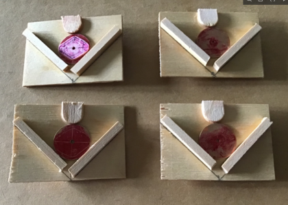
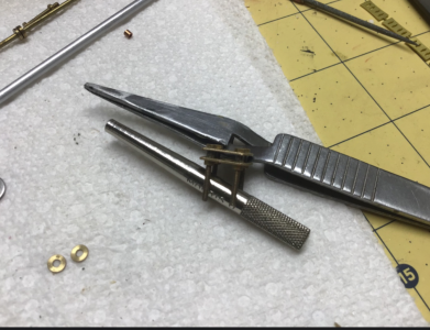
Before cutting any brass, he built a simple positioning jig that would accurately locate each component during soldering. This small fixture proved to be one of the keys to the entire project.

Machining the Components​

The side plates were fabricated from brass sheet.

Tiny brass discs became the pulley sheaves.

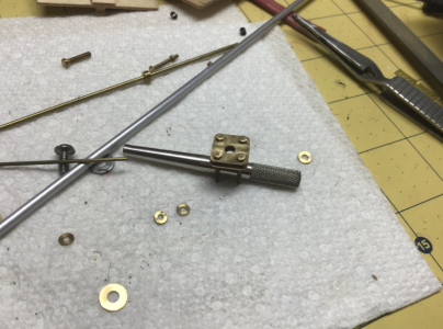
Small brass tubing and rod formed the center bushing and spacer posts.

Every hole was drilled before final shaping to maintain perfect alignment.

Building the Assembly​

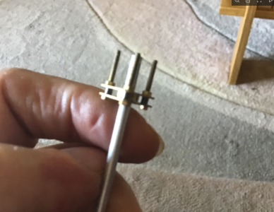
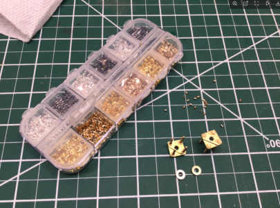
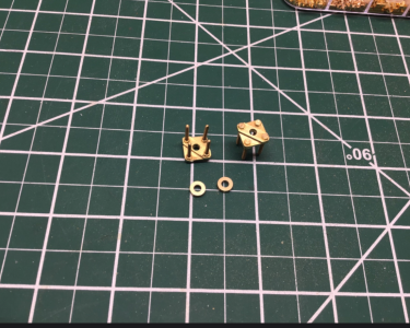
Using the alignment jig, the four spacer posts were soldered precisely between the two brass plates.

The sheave remained free to rotate while everything stayed perfectly square.

Working at this scale leaves almost no margin for error, so each part was repeatedly test-fitted before moving to the next operation.

Final Shaping​

After soldering, the assemblies were carefully filed, polished, and cleaned.

Small brass washers completed the detail while maintaining the correct spacing around the sheave.

Although each completed fitting measures only a few millimeters across, the finished appearance closely matches the full-size hardware.

Installed on the Model​

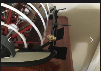
Once installed at the stern, these tiny brass assemblies become focal points of the steering mechanism.

Most people viewing the completed model will probably never realize how much work went into making these miniature fittings.

Model builders, however, will immediately appreciate the craftsmanship involved.


Special Thanks​

All credit for designing and fabricating these beautiful miniature brass steering sheaves belongs to my good friend John ("Gravman").

His willingness to share not only the finished parts, but also the complete construction process, makes this hobby even more enjoyable. The simple alignment jig he devised is an excellent example of how thoughtful planning can transform an extremely difficult scratch-building project into one that is both accurate and repeatable.

1.png

2.png

3.png

4.png5.png

6.png

7.png

8.png

9.png

10.png

11.png

12.png

13.png

14.png

15.png

16.png

17.png

18.jpeg

19.png
 

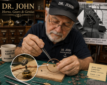
Meet John ("Gravman")​

A Craftsman Behind the Miniatures​

Before continuing with this build log, I'd like to introduce the gentleman responsible for many of the remarkable scratch-built components that have appeared throughout this project.

Many members of Ships of Scale know him by his forum name, Gravman. I simply know him as my good friend, John.

John has an extraordinary ability to look at a photograph of an original part, study its construction, and then reproduce it in miniature using nothing more than brass, patience, and an impressive amount of ingenuity. Whether it's miniature gears, working horns, steering hardware, tiny winches, or the beautiful steering sheaves featured in this update, his workmanship continually amazes me.

What makes John special isn't just his machining skills. He is always willing to explain how he solves a problem, share his techniques, and encourage other builders to try something they may have thought impossible. His willingness to pass along his knowledge is every bit as valuable as the parts he creates.

Many of the details that have brought my Juanita to life simply would not exist without his generous help and countless hours spent at his workbench.

John, thank you for your friendship, your generosity, and for allowing me to share your craftsmanship with the Ships of Scale community. It has been a privilege to learn from one of the finest model builders I have ever known.

— Julian Nodarse

20.png
 
The historic city of Marietta, Ohio sits at milepost 187 on the Ohio, River. It is by Midwest USA standards very old, established in 1788. Every September the city holds its annual Sternwheeler Festival. This year it will be held over the weekend of September 14-16. This will be the festival’s 50th anniversary. I was there for the first but moved away later so don’t know the details of this year’s celebration.

Typically, the event features a lineup of small sternwheel wheel boats like Juanita moored along Marietta’s levy and a spectacular fireworks display over the Ohio River. Marietta’s own sternwheeler, the Valley Gem is also featuring trips through the hand operated locks on the Muskingum River.

I wonder if your sternwheeler Juanita will be attending.

Roger


Roger, what a coincidence! I actually sent an email to Bruce, one of the photographers who covers the Sternwheeler Festival, while I was building Juanita, asking if he had any detailed photographs of her, especially the pilot’s console. Unfortunately, he never answered.

But this is an event I would absolutely love to attend and assist with, and with your input, I probably will make plans to be there. And yes, Juanita always takes part in the fleet and helps out wherever she can. It would be wonderful to see her back there again!

Thanks for sharing this, Roger. You may have just given me another reason to make the trip!
 
You can find info about the Sternwheel festival on Facebook. Marietta is an interesting place. It has been gentrified since I left there in 1990. In addition to the Sternwheel festival there’s the Campus Marcus Museum that encompasses buildings from the original settlement. There’s also the Ohio River Museum that includes the steam powered towboat W.P. Snyder. I believe that the museum may be closed for renovation but the towboat is open. The old Lafayette Hotel is adjacent to the levee where the sternwheelers moor and may be the headquarters for the festival. It used to have on display some riverboat stuff.

Roger
 
Thank you, Roger.
I really appreciate you taking the time to share all of that information.

It sounds like Marietta is much more than just the Sternwheel Festival.
The Campus Martius Museum and the Ohio River Museum have both been on my "wish list" for a long time, especially to see the W.P. Snyder. I understand the museum itself is undergoing renovations, but I'm glad to hear the towboat has remained a major attraction.

The Lafayette Hotel also sounds like a place every riverboat enthusiast should visit. I had no idea it was so closely connected with the festival and the town's river heritage.

If I ever make the trip from Miami, I'll definitely plan on spending several days there instead of just attending the festival.
Between the sternwheelers, museums, historic district, and river history, it sounds like a model builder could easily stay busy all week.

Thanks again for the recommendations. They're now officially part of my travel notes!
 

New Catwalk Support and Sundeck Supports​

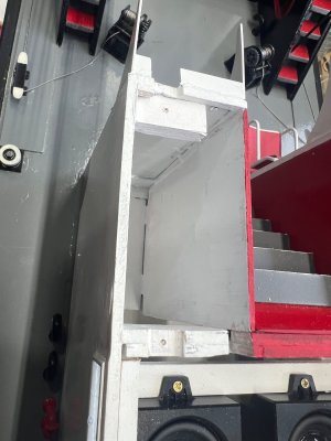
This is an update to the catwalk support that I posted some time ago.
The redesign was suggested by my good friend John, and after giving it some thought, I decided to follow his idea. While making the new catwalk supports, I also fabricated matching sundeck supports using the same construction methods and materials.

The original kit supports are made from thin styrene, and unfortunately, a couple of them broke during handling.
Since these supports are rather exposed, I decided to replace them with something considerably stronger.

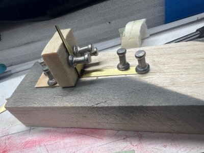
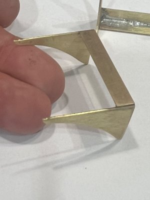
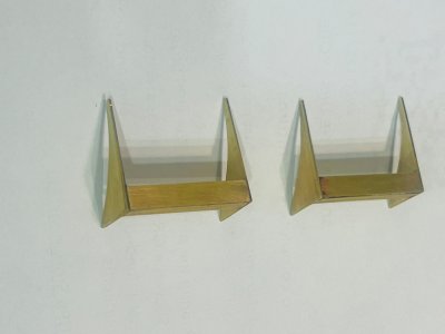
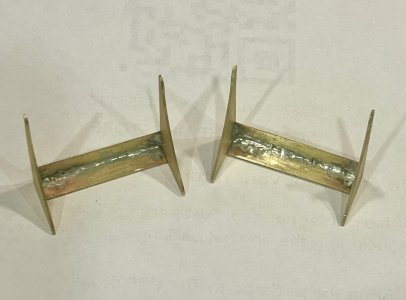
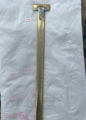
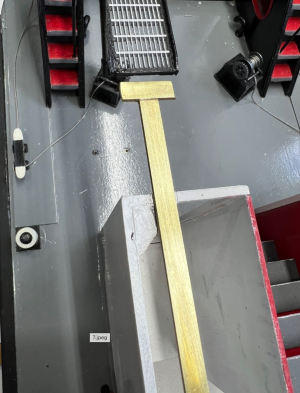
To create a permanent solution, I replaced them with supports fabricated from 2 mm × 5 mm × 120 mm brass strip, producing a much stronger and more durable assembly.

I also decided to make matching supports for the sundeck at the same time.

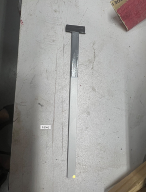
Step 1 — Original Kit Supports​

The original supports supplied with the kit are molded in thin styrene. They look fine once installed, but they are quite delicate and can easily be damaged while working around the model.

Step 2 — Planning the New Supports​

I decided to fabricate the replacements from 2 mm × 5 mm × 120 mm brass strip. The goal was to keep the appearance of the original supports while making them substantially stronger.

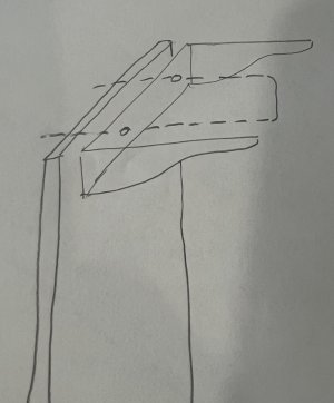
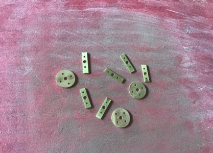
Step 3 — Fabricating the Side Plates​

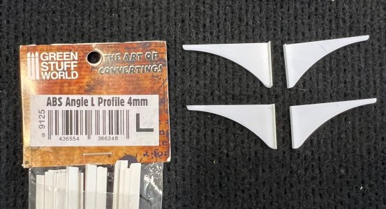
Four small brass side plates were cut and prepared. These form the attachment points for the new supports.

Step 4 — Making the U-Shaped Supports​

The actual supports were formed from the 2 mm × 5 mm brass strip. I made a simple soldering jig to hold everything in the correct position while assembling the pieces.

Step 5 — Adding the Mounting Bar​

Once the U-shaped portions were completed, the mounting bar was soldered into place. This produced a much more rigid assembly than the original styrene parts.

Step 6 — Test Fitting​

Before painting, each support was test-fitted on the model to make sure the dimensions and angles were correct and that everything lined up properly with the catwalk and sundeck.

Step 7 — Painting​

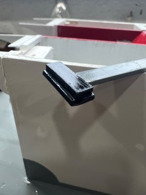
After everything was completed and cleaned up, the brass assemblies were painted to match the surrounding structure.

Step 8 — Final Installation​

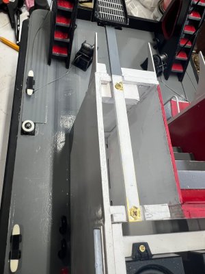
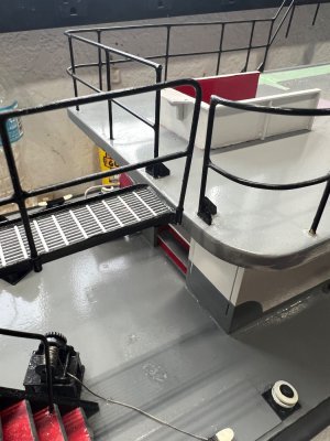
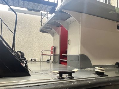
The new brass supports were then installed on the model. They are considerably stronger than the original kit parts, while still maintaining the appearance of the prototype.

I am especially happy with the way the sundeck supports turned out. Making them at the same time as the catwalk supports also gives the model a more consistent appearance.

Once again, thanks to John for the suggestion. Sometimes another builder looking at a problem from a different angle comes up with the best solution!

More progress to come on the Juanita.

2.jpeg

3.jpeg

4.jpeg

5.jpeg

6.jpeg

7.jpeg

8.jpeg

9.png

10.png

11.jpeg

12.png

13.jpeg

14.jpeg

15.jpeg
 
I am very happy to work this project with Julian. He has really helped me with my model. He is a master craftsman. There were things in the build that I didn’t understand but he walked me through the process. I am afraid I would have ended up with the wheel on the wrong end. Julian blazed the trail and I followed.
 

Juanita Lighting Installation — Part 1​

Power Supply, Servo and Master ON/OFF Switch​

It’s been a while since I posted anything because, after spending many hours moving things around, rearranging, and trying to figure out where all the components were going to fit, I finally mustered up the courage to start connecting everything!

To be honest, getting to this point was probably more intimidating than actually doing the wiring. I kept looking at all those wires, switches, LEDs, batteries, and components and thinking, “Okay… now I actually have to connect all of this!”

So, here we go!

First and foremost, I would like to say that I am not an electronics-savvy modeler like many of the members of this forum. My approach may look somewhat antiquated to some of you, but for now this is the best way I could think of to accomplish what I wanted. Hopefully, showing the process step by step might also help some of the newcomers who, like me, don't have a high level of electronics knowledge.

For this project, I decided to use Evan Designs components throughout the lighting system. Their 3-volt LEDs are already prepared for direct connection to a 3V DC power source, which made them a very good choice for someone like me who wanted to keep the electronics as simple as possible.

I used their 3V LEDs, wiring components, and battery holder as the foundation of the system. Evan Designs specifically designs these LEDs to work from a 3-volt source, which eliminated a lot of the calculations and component selection that would otherwise be necessary.

A small modification to the battery holder​

There is one modification I made to the Evan Designs battery holder that is worth mentioning.

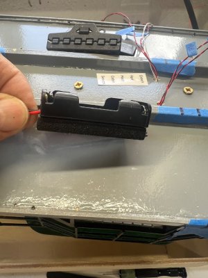
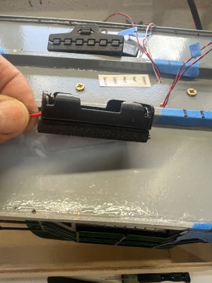
The battery holder originally came with a capacitor installed across the power leads. As you can see in Photo #9, I removed that capacitor before completing my wiring.

The reason I removed it was not because there was anything wrong with the Evan Designs component. The capacitor is there for filtering/suppressing electrical noise, but for my particular application I wanted the simplest possible 3V battery circuit feeding my master switch and individual LED circuits. Since I was not using a complicated electronic lighting controller or a circuit that required that filtering, I chose to remove it and keep the battery output as straightforward as possible.

Again, this is simply the way I chose to build my system, not a recommendation that everyone should remove the capacitor from their Evan Designs battery holder. If you are using the holder in a different application, there may be a good reason to leave it in place.

Step 1 — The power source​

I started with the Evan Designs 3V AA battery holder as the power source for the entire lighting system.

The holder uses two AA batteries to provide the 3 volts required by the Evan Designs lighting components. One of the things I liked about this arrangement is that it gives me considerably more capacity than a small coin-cell battery while still keeping the system completely independent from the boat's main power system.

My intention was to have a dedicated power source just for the lighting.

Step 2 — Installing the servo​

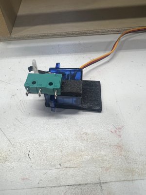
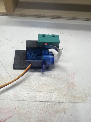
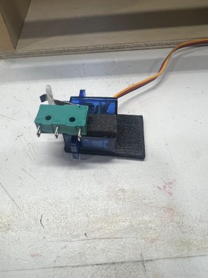
The next part of the system is the small blue servo shown in the photographs.

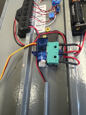
The servo itself isn't being used to control a rudder or any other mechanical function. Its only job is to operate the lighting system's master ON/OFF switch.

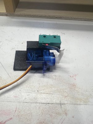
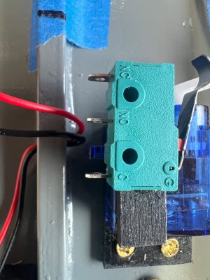
I mounted the servo on a small black mounting plate and positioned it so that its arm could move the actuator on the microswitch.

This allows me to turn the lighting system on and off remotely rather than having to reach inside the model every time I want the lights operating.

Step 3 — The microswitch​

This is where my "old-school" approach comes into play.

I mounted a small three-terminal microswitch directly above the servo. The servo arm operates the metal lever on the microswitch.

The three terminals on the switch are marked:

C — Common
NO — Normally Open
NC — Normally Closed


For my application, I used the appropriate common and normally-open connections so that the lighting circuit remains OFF until the servo moves the switch.

It's a very simple mechanical arrangement, but it works extremely well for what I need.

Step 4 — Connecting the battery to the microswitch​

The positive lead from the battery holder is routed to the microswitch.

The microswitch then acts as the master ON/OFF switch for the entire lighting system.

This was important to me because I wanted one point where I could completely disconnect the battery from all of the lighting circuits.

Once the master switch is OFF, everything is OFF.

Step 5 — Testing the servo and microswitch​

Before connecting all of the lighting circuits, I tested the servo and microswitch by themselves.

I adjusted the servo position and the metal actuator so that the servo could operate the microswitch positively without putting excessive pressure on it.

There was a little trial and error involved here.

The goal was simple:

Servo moves → microswitch changes state → lighting system turns ON.

And when the servo returns:

Microswitch opens → lighting system turns OFF.

Once I was satisfied with that operation, I was ready to move on to the actual lighting circuits.

And that's where the fun—and all those wires—really began!

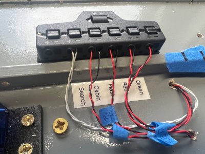
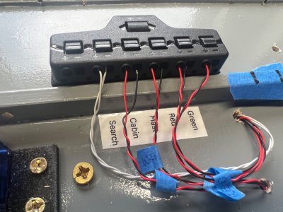
In Part 2, I will show how I connected and organized the individual lighting circuits for the Search Light, Cabin, Mast, Red Navigation Light, and Green Navigation Light.

I hope this helps some of the other modelers who, like me, may look at a pile of wires and electronic components and think, “Where in the world do I start?”

Sometimes the best answer is simply:

Start with one wire at a time.

1.jpeg

2.jpeg

3.jpeg

9.jpeg


4.jpeg

5.jpeg

Everything was kept under the Sundeck leaving only the servo for hooking up with the receiver.

6.jpeg
 

Juanita Lighting Installation — Part 2​

Running the Wiring to the Stern Mast​

Welcome back to Part 2 of my Juanita lighting installation.

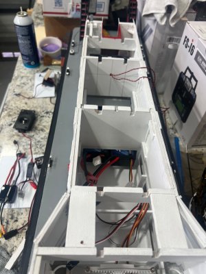
Now that I had the pilot house lighting circuits connected and working, I still had to figure out how I was going to get the wiring from the main lighting area all the way back to the stern mast.

This presented another little modeling challenge.
Rather than simply letting the wires run loose through the superstructure, I wanted to protect them, keep them organized, and make the installation look as clean as possible.
So, once again, I came up with a very simple solution.

Step 1 — Making room for the wiring​

My first job was to create a path for the wiring through the superstructure.

I carefully cut grooves into the inside walls of the superstructure to accommodate a length of PVC tubing.
The tubing would eventually carry and protect the wires running from the stern mast toward the main lighting distribution area.
I wanted the tubing to sit neatly inside the structure rather than having wires hanging or rubbing against the walls.

Step 2 — Painting the PVC tubing​

Once I had the grooves cut and was satisfied with the fit, I painted the PVC tubing the same color as the sundeck.

This was an important little detail for me.
Even though the tubing would be mostly hidden, I didn't want to install something that would look completely out of place if it happened to be visible.
Matching the surrounding structure helps make the installation look like it belongs there.

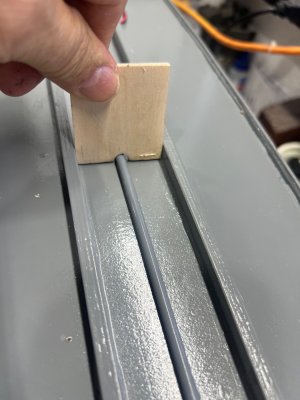
Step 3 — Making a simple jig​

This is one of those little tricks that costs practically nothing but makes a big difference.

I made a simple wooden jig to hold the PVC tubing in the correct position while I glued it underneath the sundeck.
The jig allowed me to keep the tubing centered and straight while the adhesive set.
Trying to hold a long piece of tubing in exactly the right position by hand would have been much more difficult.
The jig made the job considerably easier.

Step 4 — Installing the PVC tubing​

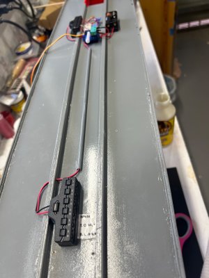
With the jig holding everything in alignment, I glued the PVC tubing along the centerline underneath the sundeck.

Once the adhesive had cured, I removed the jig and was left with a clean, straight wiring channel.
The tubing now provided a protected route for the wires running between the stern lighting and the main lighting system.

Step 5 — Running the wiring​

I then began routing the wiring through the PVC tube.

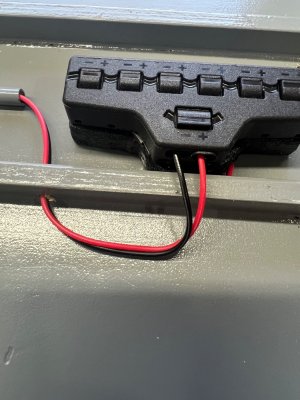
The purpose was to bring the wires from the stern mast forward to the main lighting area, where I already had the remaining positions available on the six-position splitter.
This allowed me to use the existing lighting system rather than having to install another completely separate power source or switching system for the stern mast.

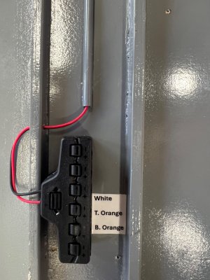
Step 6 — The stern lighting splitter​

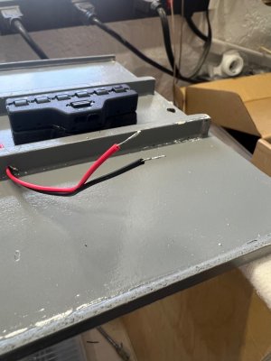
At the stern, I installed another splitter to organize the mast-light connections.

Just as I had done with the pilot house lighting, I wanted to know exactly what each wire controlled.
So I added small labels identifying the individual circuits.
This may seem like a minor detail, but I have learned that labeling wires while you are building is much easier than trying to figure them out months later!

Step 7 — Connecting the stern mast​

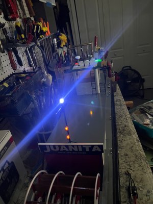
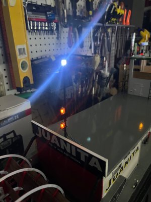
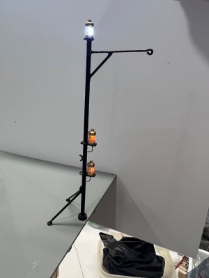
The stern mast contains several lights, including the two red lights and the white light at the top.

I connected their wiring and routed everything neatly back through the PVC tubing toward the main lighting system.
The tubing keeps the wiring contained and protected while also keeping it out of sight as much as possible.

Step 8 — Connecting everything together​

Once the stern mast wiring had been routed through the PVC tube, I connected it to the remaining positions on the main six-position splitter.

At this point, I finally had the entire lighting system connected together:

  • Pilot house lighting
  • Search light
  • Cabin/interior lighting
  • Mast light
  • Red navigation light
  • Green navigation light
  • Stern mast lighting
Everything now shared the same master power system that I described in Part 1.

Step 9 — The moment of truth!​

After spending all those hours measuring, cutting grooves, installing tubing, making the jig, routing wires, soldering connections, labeling everything, and checking each circuit, there was only one thing left to do.

Turn it on!

And...

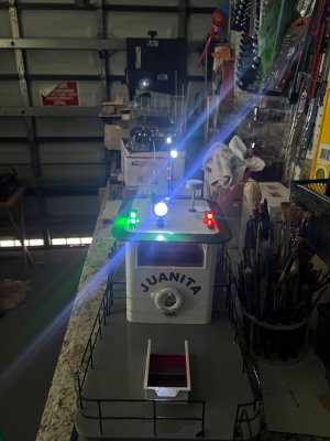
Everything worked!

I have to admit, seeing all the lights come on for the first time was a fantastic feeling.
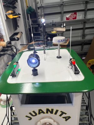
The white lights, the green and red navigation lights, the search light, and the lights on the stern mast all came to life.
After all the head-scratching and wire chasing, it actually worked exactly the way I had hoped.

Step 10 — A few final photographs​

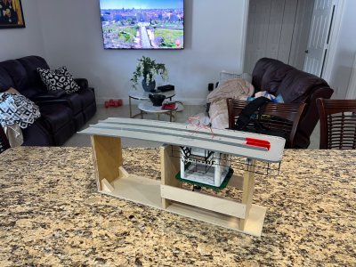
The final photographs show the Juanita with the lighting system operating.
The stern mast lights really make a difference, especially the two red lights and the white light at the top of the mast.
The search light is particularly bright, and the navigation lights give the pilot house a completely different appearance.
For me, this was one of those moments where you step back from the workbench and think:

"Yep... it was worth all that work!"

Final thoughts​

Once again, I want to emphasize that I approached this project as a model builder rather than an electronics expert.

There are probably a dozen more sophisticated ways to accomplish what I did here.

But I wanted a system that I could understand, troubleshoot, repair, and modify myself.

The PVC tubing, the simple jig, the labeled circuits, the individual splitters, and the servo-operated master switch all came from trying to solve one problem at a time.

That's really the way I build models.
I don't necessarily know the perfect solution when I start.
I just try to figure out the next problem in front of me.
And eventually, one problem at a time, you end up with something that works.

I hope these two posts might encourage some of the other modelers who have been thinking about adding lighting to their models but have been intimidated by the wiring.

Don't be afraid of it.

Plan it out, label everything, take your time, and work on one circuit at a time.

And most importantly...

Have fun building!

Thanks for following along with my Juanita lighting installation. I hope you enjoyed the journey as much as I did.

Now, on to the next part of the build!

18.jpg

19.jpeg

20a.jpeg

20b.jpeg

21.jpeg

22.jpeg

23.jpeg

24.jpeg

27.jpeg

29.jpeg

28.jpeg

30.jpeg

31.jpeg
 

The Pilot House Console​

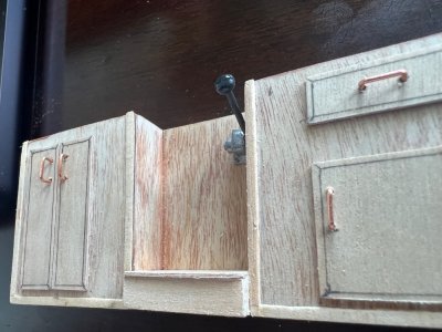
This tiny 4¼-inch-wide console has been the most detailed scratch-built assembly of the entire Juanita project. The challenge was not the woodworking—it was the research. As far as I have been able to determine, there is only one photograph of the actual Juanita pilot house console available on the internet, and it was taken from an angle that hides many of the details.

Recreating it became a true detective project. By enlarging the original photograph, studying every shadow, comparing it with modern towboat controls, and using AI to help interpret hidden details, I slowly pieced together what the console must have looked like. Every handle, cabinet door, switch, and fitting had to be designed and fabricated from scratch.

Construction Sequence​

  • Studied the only known reference photo of the real Juanita console, enlarging it repeatedly to identify every visible feature.
  • Designed the cabinet layoutbased on proportions visible in the photograph, including:
    • Port storage cabinet with double doors.
    • Starboard drawer and lower cabinet.
    • Center opening for the operator.
    • Raised footrest beneath the center opening.
  • Scratch-built the entire cabinet from basswood sheet and strip stock.
  • Added individually framed doors and drawer fronts to duplicate the recessed panel construction of the original.
  • Installed handmade copper wire door pulls bent to identical shapes.
  • Built the center document holder mounted on the rear panel.
  • Designed and fabricated the throttle control assembly, including:
    • Cast-looking mounting block.
    • Pivot housing.
    • Four simulated mounting bolts.
    • Pivot bolt detail.
    • Black control lever.
    • Rounded control knob.
  • Scratch-built both steering tiller arms, carefully shaping them to match the profile seen in the original photograph.
  • Finished the steering arms in aluminum with weathered metallic highlights.
  • Turned two miniature brass control knobs for the compass compensator using brass fittings, then mounted them on insulating white bases exactly like the prototype.
  • Fabricated the brass compass compensator plate, polishing it to a mirror finish before installation.
  • Installed the electrical switch panel, reproducing the four-button appearance visible in the reference photograph.
  • Added the ignition/key switch on the port side of the console.
  • Built and installed the VHF radio microphone cradle, then added:
    • Hand microphone.
    • Coiled microphone cord.
    • Radio mounting bracket.
  • Applied multiple coats of wood stain and clear finish to reproduce the warm varnished appearance of the real pilot house cabinetry.
  • Performed repeated test fitting of every individual component before permanent installation to ensure proper spacing and alignment.

Details Worth Mentioning​

  • The throttle quadrant alone required several separate miniature parts and went through multiple redesigns before I was satisfied with its appearance.
  • The brass compensator assembly was made almost entirely from modified brass hardware, proving once again that ordinary materials can become convincing scale fittings with a little imagination.
  • The radio microphone and its coiled cord add a surprising amount of realism despite being only a few millimeters in size.
  • Every cabinet handle was bent individually from fine copper wire.

Final Thoughts​

Although this console measures only 4¼ inches (108 mm) wide, it contains dozens of individually fabricated parts. It became one of those projects where every evening's work produced only a few additional details, yet each one brought the model closer to the character of the real Juanita.

Looking back, this little console perfectly captures what this build has become: not simply assembling a kit, but researching, interpreting, and recreating a vessel for which very little documentation exists. Sometimes the smallest assemblies demand the greatest amount of patience, and in this case, the effort was well worth it.

Only thing missing are the gauges and Gravman is helping me creating this tiny wonders.

REAL JUANITA CONSOLE
View attachment 625810

View attachment 625804

View attachment 625805

View attachment 625806

View attachment 625809

View attachment 625803

View attachment 625800
View attachment 625798


REAL VHF RADIO
View attachment 625794

SCRATCH BUILT RADIO
View attachment 625792


View attachment 625793

View attachment 625799

View attachment 625795

View attachment 625793

View attachment 625796

View attachment 625801

View attachment 625802
wow that is amazing work!!
 

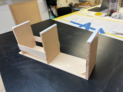
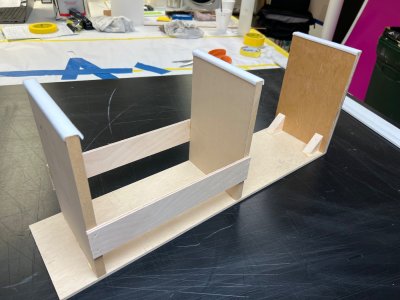
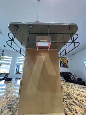
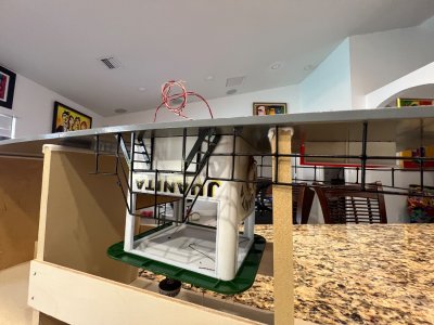
Juanita — A Strange but Useful Contraption!​

This weird-looking contraption is what made my life much easier while wiring the sundeck.

After spending a few days trying to figure out how to turn the sundeck upside down so I could work underneath it, I finally came up with this crazy-looking setup.

It may not win any beauty contests, but it works!

It holds the sundeck securely and gives me easy access to all the wiring. And the best part? I can now use it as a work stand whenever I need to work on the wiring underneath.

Sometimes, you just have to build the tool you need!

1.jpeg

2.jpeg

3.jpeg

4.jpeg

5.jpeg
 

Pilot House Lighting Installation – Part 1​

With most of the exterior work on the Juanita's Pilot House completed, I turned my attention to the lighting system. My goal was to keep the installation as neat and accessible as possible while allowing the individual lights to be controlled separately.

All of the wiring, LED lights, battery holder, and wiring harness used for this installation came from Evan Designs.

I will be using several small switches for the navigation lights, mast light, cabin lighting, and searchlight. I also wanted a simple servo-operated master switch so the entire lighting system could be turned on and off remotely.

Here is the first part of the installation:

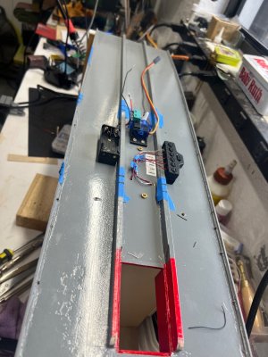
Picture 1:
The micro switch mounted on its base together with the servo. This assembly will be used as the remote master switch for the lighting system.

Picture 2:
Another view showing how the servo arm operates the micro switch. The movement is simple and positive, which should make it very reliable.

Picture 3:
The switch assembly temporarily positioned inside the model. I wanted to make sure there was enough clearance before permanently mounting everything.

Picture 4:
A closer view of the mounting arrangement. The servo and switch are secured to a small platform so the entire unit remains stable.

Picture 5:
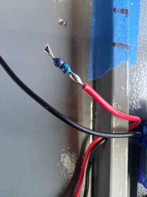
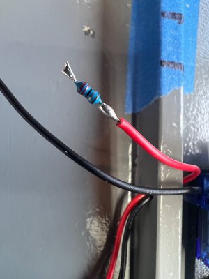
One of the electrical connections being prepared. I soldered the wiring carefully and added a resistor where required for the LED circuit.

Picture 6:
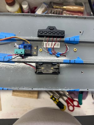
The six-switch control panel installed. Each switch will control an individual lighting circuit: Searchlight, Cabin, Mast, Red navigation, and Green navigation lights.

Picture 7:
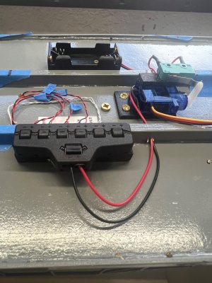
A wider view showing the relationship between the switch panel and the servo-operated master switch assembly.

Picture 8:
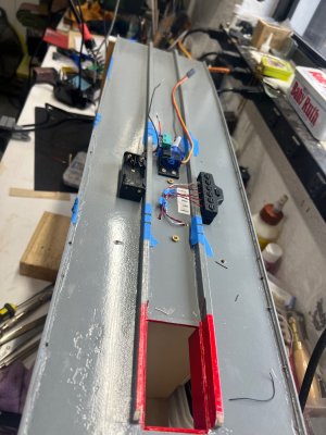
An overall view of the installation area. At this stage I was still routing and organizing the wiring before making the final connections.

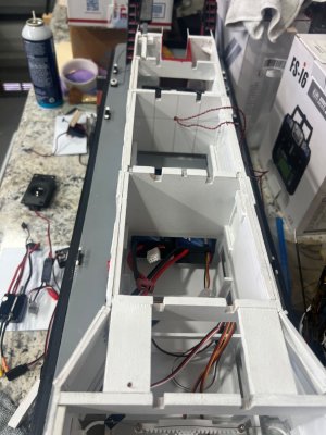
Picture 9:
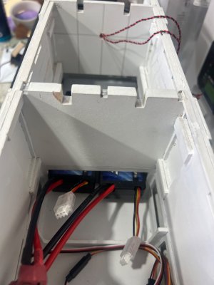
Looking down inside the Pilot House structure. The wiring from the various lights is routed through the compartments and will eventually connect to the control system below.

This is still a work in progress, but the basic layout is now established. The next step will be connecting the individual lighting circuits and testing everything before closing up the Pilot House.

1.jpeg

2.jpeg

3.jpeg

4.jpeg

5.jpeg

6.jpeg

7.jpeg

8.jpeg

9.jpeg
 
Back
Top