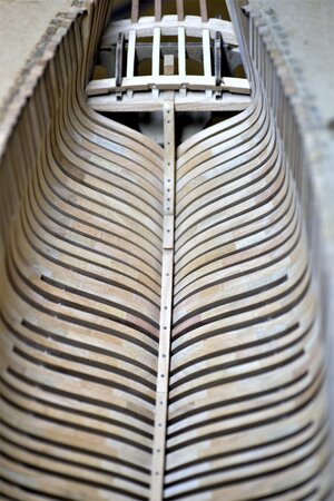
The Naval Cutter ALERT- 1777, POF by Jimsky

Hi Jim,

Sorry but I think you are incorrect.
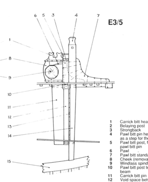
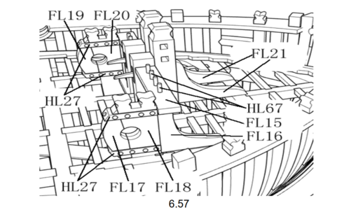
The Trident model has the improved modified E3/5 bitt construction. The modell has a separate pawl bitt post, the original had the pawl in the main bitt post and no separate pawl bitt.
So the notch facing to the bow is correct for the Trident configuration.

Aots modified
1610657758737.png

Trident
1610658728676.png
 
You are 100% correct, my friend!!! This why the group build is mostly valuable! I really appreciate your precise eye for details, and hope I didn't mislead anyone in their assemblies.

Memorandum: Due to constant mistakes and careless assembly, the shipwrights and the supervisor has been fired (without pay) and the kit assembly halted! :(

**** I have edited post # 378 at the beginning, pointed to Maarten's findings, and the correct placement of the part DL3 in our kit.
 
Well I hate to dissapoint everyone, but iy does not matter which way you, the ends di not line up with the notches in the lower beams. I have just completed this section!. Video in my build. Plus if you add the cabin walls at the front it all becomes moot as the item indicated as 14 has to be chope dto fill the wall and 12 does not exist!. Also ignore the number part sin the trident kit as they are wrong! The post marked 11 is the windlass posit and is not connected to the bits.

Don't stress over it. Its does not matter in the long run and if you add the cabins & flooring its not relavent.

Cheers
 
Don't stress over it. Its does not matter in the long run and if you add the cabins & flooring its not relavent.
Thank you so much, Paul. At least, it is a relief, that my mistake may not ruin someone's build. But this build...I am afraid is...halted :eek: Is it??? ;)
 
Hi Jim, what is the status of your build? Hope it isn't halted?
In respect to the bitt and winch it is not a major issue we will all find a good solution for fitting it. The lower beam position for me will be irrelevant as you will see later.
 
Hi Jim, what is the status of your build? Hope it isn't halted?
In respect to the bitt and winch it is not a major issue we will all find a good solution for fitting it. The lower beam position for me will be irrelevant as you will see later.
Thanks, Mon Amie! The build is not halted (no way)! I understand, that in this particular kit, at least in my build, the position of this beam is relative. I was more worried, to mislead others... :(

The shipwrights returned to the field, and the supervisor was hired back on a trial basis, for a few months probation. Updates to follow soon.
 
I was more worried, to mislead others... :(
You should never feel that way. The same goes for Uwe in Le Coureur group and other 'pioneers'. Nobody ever told us to follow in your footsteps.
I'm more than happy to make a first track in La Grave but here I gladly take all the huge advantages of following the masters. That does not mean I should blindly follow when the master falls in a crevasse or is hit by an avalange. As adult people we can never outsource the responsibility for the things we do to somebody else.
 
Most of us are silent, hidden from posts. We look and share nothing, but we take advantage of new ideas, personal techniques and above all the mistakes of YOU that you share. You will never be appreciated enough for all of this. Here in this log, as in many others, I thank you and ask you not to stop.
 
Hello everyone! At firsts, I would love to thank @Maarten @PoulD @Enzo @paulv1958 for the greatest support and encouragement, and all other readers for your attention and 'likes'.

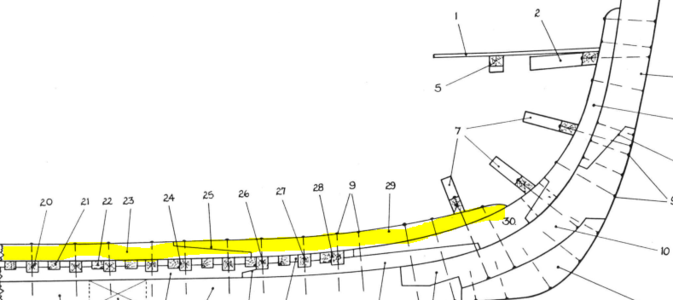
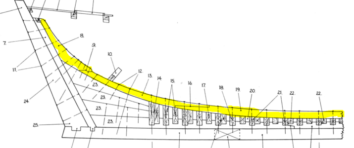
Today, a long-promised, we will continue our build with the long timber called Keelson. Take a look at the below images from the AOTS book, which we constantly using as the reference. As you can see (highlighted yellow), the Keelson divided into 3 timber sections and Sternson knee, joined by the Keelson scarphs. Let's identify those parts.

1611704408679.png

The first section (29) is the Fore section of the Keelson joined with the Middle section (23) by the scarph joint (25)

1611704805881.png

The Middle section connects with the After section of Keelson (13) by Keelson scarph (16). The last piece of keelson (8) Sternson knee.
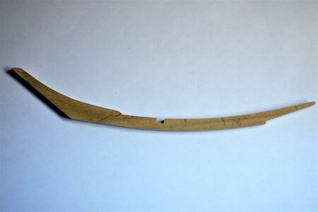
In the kit, the Keelson sections represented the same way and identified with parts BL-12 (Fore section), BL-13 (Middle section), BL-14 (After section), and BL-15 (Sternson knee). All of those sections are connected by nicely CNSed scarphs joints.

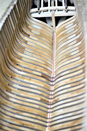
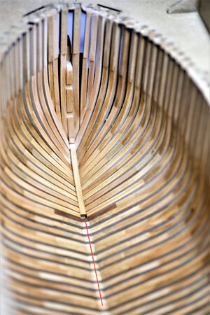
1611707974528.png

All parts made are fitt together very-well, but before gluing them in-place make sure the surface is even and all the adjacent frames creating a nice smooth curve. If you have some frames 'stick out' or lover then another - make them even with a small sanding stick. (red ➡ )

600_1120.jpg600_1121_E.jpg

Here is the 'After section' is glued using the scarph with Sternson knee

600_1124.jpg

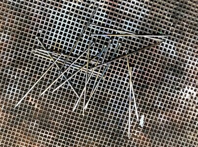
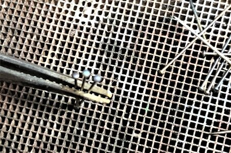
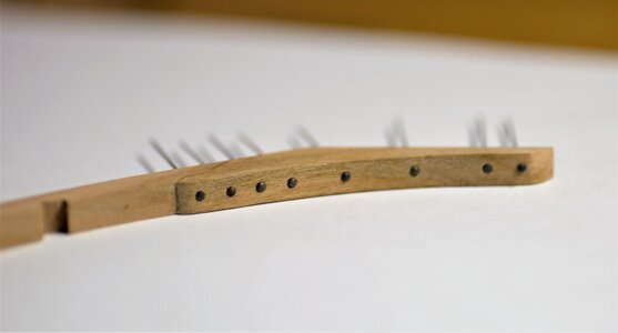
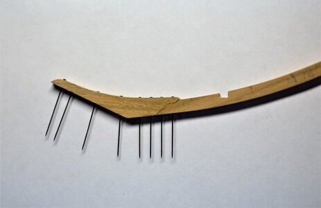
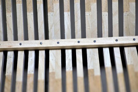
The entire Keelson attached by bolts to every second frame, I decided to represent bolts with sewing pins. The ping itself is 0.59mm and the head is 1.20mm. Those are shiny steel pins and I give those a special treatment to make them usable. I put the torch flame to the head area only until it just turns red. As the result, I was rewarded with the effect I expected: steel blue.

IMG_1836.JPEG IMG_1837.JPEG

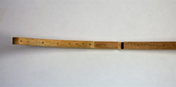
...also, I measured all the bolt's positions and predrilled the holes for further convenience.

600_1125.jpg
600_1128.jpg
600_1127.jpg
In the same way, other Keelson sections were assembled\laid and bolted.

600_1134.jpg

600_1133.jpg
The final result.
600_1131.jpg

The next will be fitting the Limberstrakes and the Thickstuff alone with mast foot. To be continued...
 
Hello everyone! At firsts, I would love to thank @Maarten @PoulD @Enzo @paulv1958 for the greatest support and encouragement, and all other readers for your attention and 'likes'.

Today, a long-promised, we will continue our build with the long timber called Keelson. Take a look at the below images from the AOTS book, which we constantly using as the reference. As you can see (highlighted yellow), the Keelson divided into 3 timber sections and Sternson knee, joined by the Keelson scarphs. Let's identify those parts.

View attachment 208858

The first section (29) is the Fore section of the Keelson joined with the Middle section (23) by the scarph joint (25)

View attachment 208859

The Middle section connects with the After section of Keelson (13) by Keelson scarph (16). The last piece of keelson (8) Sternson knee.
In the kit, the Keelson sections represented the same way and identified with parts BL-12 (Fore section), BL-13 (Middle section), BL-14 (After section), and BL-15 (Sternson knee). All of those sections are connected by nicely CNSed scarphs joints.

View attachment 208867

All parts made are fitt together very-well, but before gluing them in-place make sure the surface is even and all the adjacent frames creating a nice smooth curve. If you have some frames 'stick out' or lover then another - make them even with a small sanding stick. (red ➡ )


Here is the 'After section' is glued using the scarph with Sternson knee

View attachment 208870

The entire Keelson attached by bolts to every second frame, I decided to represent bolts with sewing pins. The ping itself is 0.59mm and the head is 1.20mm. Those are shiny steel pins and I give those a special treatment to make them usable. I put the torch flame to the head area only until it just turns red. As the result, I was rewarded with the effect I expected: steel blue.

View attachment 208879 View attachment 208880

...also, I measured all the bolt's positions and predrilled the holes for further convenience.

View attachment 208881
View attachment 208882
View attachment 208883
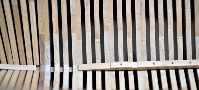
In the same way, other Keelson sections were assembled\laid and bolted.

View attachment 208890

View attachment 208887
The final result.
View attachment 208888

The next will be fitting the Limberstrakes and the Thickstuff alone with mast foot. To be continued...
Fantastic Jim. A simple solution with a brilliant result!
 
Have you drilled these all the way through the keel?
Hello, my friend. I drilled halfway through the keel using the smaller drill bit 0.55mm (the ping is 0.59mm). Then I push the bolt's head with pressure (no glue). But the Keelson segments are glued to the frames using Elmer's Max (PVA) glue.
 
Back
Top