The Naval Cutter ALERT- 1777, POF by Jimsky

Hello Jim, a very successful and beautiful, clean work! The inspector was probably also very satisfied.Especially the tiny little parts require a steady hand, the best eyes and ingenuity - you have plenty of everything, congratulations!
Maybe I may give a little hint (not meant in a know-it-all way): The diagonal part at the upper end of the Z-wood at the doors should point outwards, the inner part inwards. At least that's what I think I saw on old barn doors and cellar doors. But I could be wrong.
I wish you and all fellow readers a happy new year, may Corona soon disappear forever!
Many greetings
Fritz Baur (schiffbaur)
Hello, Frits. Thanks for the hint! I would love to know what is the reason for such a specific placement of the 'Z' bar. Honestly, I didn't even think of the rule. Thanks for pointing it out and Happy New Year!

Hallo Fritten. Danke für den Tipp! Ich würde gerne wissen, was der Grund für eine solche spezifische Platzierung der Z-Leiste ist. Ehrlich gesagt habe ich nicht einmal an die Regel gedacht. Vielen Dank für den Hinweis und ein frohes neues Jahr!
Hi Jim absolutely fabulous work, love it. I am jealouse.

About the door Frits @schiffbaur is correct, the reason is that an upwardplank from lower inside to upper outside bar will carry the weight of the door, if you put it the other way around like you did it will be pulling on it and not carry the weight of the structure.
 
About the door Frits @schiffbaur is correct, the reason is that an upwardplank from lower inside to upper outside bar will carry the weight of the door, if you put it the other way around like you did it will be pulling on it and not carry the weight of the structure.
Veel dank, Mon Amie! Leef en leer! Gelukkig nieuwjaar! Bottle

Many thanks, Mon Amie! Live and learn! Happy New Year! Bottle
 
Hello Jim, a very successful and beautiful, clean work! The inspector was probably also very satisfied.Especially the tiny little parts require a steady hand, the best eyes and ingenuity - you have plenty of everything, congratulations!
Maybe I may give a little hint (not meant in a know-it-all way): The diagonal part at the upper end of the Z-wood at the doors should point outwards, the inner part inwards. At least that's what I think I saw on old barn doors and cellar doors. But I could be wrong.
I wish you and all fellow readers a happy new year, may Corona soon disappear forever!
Many greetings
Fritz Baur (schiffbaur)

Translated with www.DeepL.com/Translator (free version)
I am not completely sure of what Fritz is saying about the direction of a "Z-bar" but from my old ranch days I have some familiarity with supporting gates which are just long doors. If you think of the door with hinges on the right side opening wither way on the left side, a diagonal strut coming down from the upper right hinge is in tension as the door tries to sag, holding it up. If the diagonal strut were on the top of the left open door corner coming down to the lower right which is a lower hinge point, the strut is in compression and better seated but relies on the upper right hinge to take up the counter-clockwise rotation forces and will eventually pull out letting the door sag down. The challenge with the tension diagonal is to firmly secure both ends to restrain the downward sagging force direction. With high gate ;posts on the pivoting side it is easy to secure a high diagonal down to the lower opening end of the gate and is much more secure than a diagonal in compression which also needs a supporting rod/line/strut from the post top holding up and resisting the downward sag. Doesn't answer the door issue in point but just something to consider. Rich (PT-2)
 
I am not completely sure of what Fritz is saying about the direction of a "Z-bar" but from my old ranch days I have some familiarity with supporting gates which are just long doors. If you think of the door with hinges on the right side opening wither way on the left side, a diagonal strut coming down from the upper right hinge is in tension as the door tries to sag, holding it up. If the diagonal strut were on the top of the left open door corner coming down to the lower right which is a lower hinge point, the strut is in compression and better seated but relies on the upper right hinge to take up the counter-clockwise rotation forces and will eventually pull out letting the door sag down. The challenge with the tension diagonal is to firmly secure both ends to restrain the downward sagging force direction. With high gate ;posts on the pivoting side it is easy to secure a high diagonal down to the lower opening end of the gate and is much more secure than a diagonal in compression which also needs a supporting rod/line/strut from the post top holding up and resisting the downward sag. Doesn't answer the door issue in point but just something to consider. Rich (PT-2)
Thanks, Rich. You are all correct. Apparently, there two types of bracing the wooden door or gate to prevent sagging. A brace is a diagonal piece of wood that takes a bit of the load of the nails/screws.

Type #1 TENSION BRACES

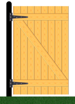
Many doors/gates have tension braces. They look like this:
1609474855035.png
A tension brace works by transferring load from the outside end of the bottom rail to the inside (hinge) end of the top rail. It ‘pulls’ the weight of the gate up to the top hinge.

Type #2 COMPRESSION BRACES

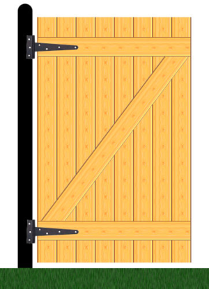
The far more common type of brace is the compression brace. They look like this:
1609475085401.png
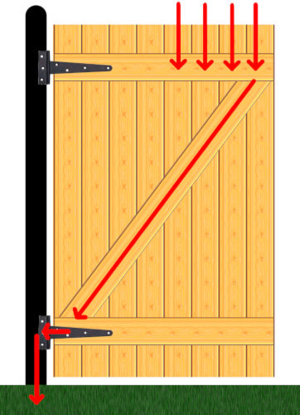
A compression brace works by transferring the load from the outside end of the top rail to the inside (hinge) end of the bottom rail. The weight of the gate ‘rests’ more on the bottom hinge. Load is transferred something like this:
1609475127352.png

Pretty-much all doors/gates require some form of bracing, but depending on size, shape and weight, you can sometimes get away with very little bracing and the type of bracing doesn’t really matter. Narrow and/or light doors/gates fall into the ‘it probably doesn’t matter’ category.
If your door is wide and/or heavy, however, then you are better off with a compression brace. A compression brace is easy for most DIYers to construct to a satisfactory standard, and is hard to screw up. Just remember:

  • Compression braces are suitable for doors where the angle between the bottom rail and the brace is greater than 45°
  • Make sure both ends of the brace have full contact with the rails
  • Put (ideally two) nails/screws through each board into the brace
Note: It is entirely possible to tension brace a wide and heavy gate — if you have a decent amount of experience with different types of joints and you know what you are doing. The average person, however, doesn’t have that experience, and doesn’t have the required carpentry skills…

The biggest advantage that compression braces have over tension braces is the way that loads are transferred. In compression, loads are distributed over the end cross-section of of the brace as well as the screws/nails — that greatly reduces the overall rate of fibre compression (which means it will sag less and last longer). Because the loads are transferred to the bottom hinge, and the bottom hinge is closer to the ground, the gate ends up more stable — it bounces up and down less. Gate posts supporting tension-braced gates also tend to bend/twist over time — because the load is transferred to the top hinge (higher from the ground, where it exerts more torque).

If compression braces have such a clear advantage, why do some sources still recommend tension braces?
Mainly due to historical reasons, but also because in a very limited number of scenarios tension is still better.

read the full article here


MUCH MUCH better than the stuff supplied!.

BTW you can see all the features through the top if you plan it correctly( ie make hatches removeable, deck flooring. Bottom lighting on the ship display stand may show it up nicely. Once out of the rig & cut down its amazing how much you can see.
 
MUCH MUCH better than the stuff supplied!.

BTW you can see all the features through the top if you plan it correctly( ie make hatches removeable, deck flooring. Bottom lighting on the ship display stand may show it up nicely. Once out of the rig & cut down its amazing how much you can see.
Thank you, Paul!! Yes, I am sure something will be seen from different angles, under different light conditions...but, for the most part, it is not a big deal. I am enjoying the process of fabricating parts, and will definitely know all the bits are there...and you guys will prove it! ;) Cannot wait to remove it from the berth...

Happy New Year!!!
 
Thanks, Rich. You are all correct. Apparently, there two types of bracing the wooden door or gate to prevent sagging. A brace is a diagonal piece of wood that takes a bit of the load of the nails/screws.

Type #1 TENSION BRACES

Many doors/gates have tension braces. They look like this:
View attachment 202745
A tension brace works by transferring load from the outside end of the bottom rail to the inside (hinge) end of the top rail. It ‘pulls’ the weight of the gate up to the top hinge.

Type #2 COMPRESSION BRACES

The far more common type of brace is the compression brace. They look like this:
View attachment 202746
A compression brace works by transferring the load from the outside end of the top rail to the inside (hinge) end of the bottom rail. The weight of the gate ‘rests’ more on the bottom hinge. Load is transferred something like this:
View attachment 202747

Pretty-much all doors/gates require some form of bracing, but depending on size, shape and weight, you can sometimes get away with very little bracing and the type of bracing doesn’t really matter. Narrow and/or light doors/gates fall into the ‘it probably doesn’t matter’ category.
If your door is wide and/or heavy, however, then you are better off with a compression brace. A compression brace is easy for most DIYers to construct to a satisfactory standard, and is hard to screw up. Just remember:

  • Compression braces are suitable for doors where the angle between the bottom rail and the brace is greater than 45°
  • Make sure both ends of the brace have full contact with the rails
  • Put (ideally two) nails/screws through each board into the brace
Note: It is entirely possible to tension brace a wide and heavy gate — if you have a decent amount of experience with different types of joints and you know what you are doing. The average person, however, doesn’t have that experience, and doesn’t have the required carpentry skills…

The biggest advantage that compression braces have over tension braces is the way that loads are transferred. In compression, loads are distributed over the end cross-section of of the brace as well as the screws/nails — that greatly reduces the overall rate of fibre compression (which means it will sag less and last longer). Because the loads are transferred to the bottom hinge, and the bottom hinge is closer to the ground, the gate ends up more stable — it bounces up and down less. Gate posts supporting tension-braced gates also tend to bend/twist over time — because the load is transferred to the top hinge (higher from the ground, where it exerts more torque).

If compression braces have such a clear advantage, why do some sources still recommend tension braces?
Mainly due to historical reasons, but also because in a very limited number of scenarios tension is still better.

read the full article here


The missing vector arrow/force is at the upper (left) hinge which has a force acting horizontally to the right (withdrawal of the hinge screws) from the weight of the door as the entire diagram is a clockwise rotation. That element is the long time weakness of this arrangement. Just my observation. Rich
 
The missing vector arrow/force is at the upper (left) hinge which has a force acting horizontally to the right (withdrawal of the hinge screws) from the weight of the door as the entire diagram is a clockwise rotation. That element is the long time weakness of this arrangement. Just my observation. Rich
This is a very interesting subject and a lot more complicated than one should think.

If the brace was made in steel instead of wood it would not matter if the door was down-braced or up-braced. But wood has different properties than steel. Wood is anisotropic. It is many times stronger parallel to the grain than it is perpendicular to the grain. A chair with legs as thin as a match would easily support a person of 100 kg if the legs was supported so they wouldn't buckle. It is even stronger (around double in average) in tension parallel to the grain than it is in compression parallel to the grain:
1609543718363.png
So with that knowledge one should think that a down-brace would be far the strongest, right? Not so! A down-braced wide door will inevitably sag, especially if it is outdoor or the door is in other ways exposed to moisture. An up-braced door is much stronger. In fact an up-braced door is even stronger than an X-braced door. How about that?

A down-brace is acting as a tie. If wood is used as a down brace the stabillity is entirely depending on the fasteners / nails and on the slight resistance to tearing that the fibers between where the nails are driven and the end of the brace offer. I case the connections in both ends of the brace is enforced by metal plates / iron straps it will be stronger but blacksmith work was expensive and even with iron straps some of the issues, e.g. premature rot, will remain. Also in case wooden dowels are used instead of nails some of the problems of this construction will remain.

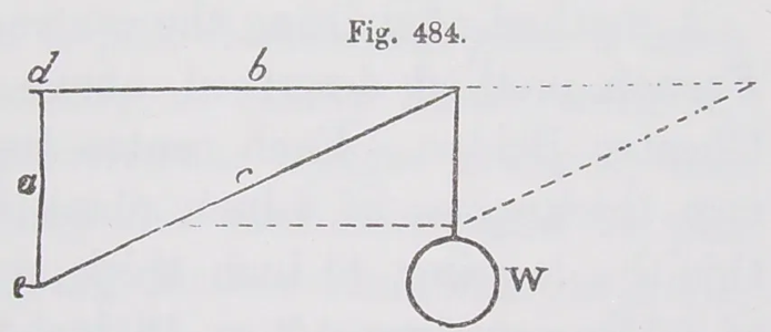
An up-brace is acting as strut. From this simple drawing from James Newlands' "The carpenters assistant":
1609543756106.png
where a is the hanging stile, b is the upper rail, c is the brace and W is the weight, is is clear that the brace is under compression and thus the only role of the fasteners is to keep the brace in place. The upper rail is under tension though so the upper hinges should ideally have a long strap (not needed for the lower hinges apart from the visual appearance). The connection between the the brace and the upper rail should be set back to some distance from the end of the rail.

Of course the hinges should be properly fastened but the tension on the hinges is the same no matter if the door is up-braced or down-braced.
 
Last edited:
This is a very interesting subject and a lot more complicated than one should think.
Our forum is very unique, we are grateful to have you, Poul, among us. You always add constructive comments to a subject. ;) Frankly, when I build those doors, I couldn't even think their construction will bring such a discussion. Live and learn!!! Many Thanks @PoulD
 
Our forum is very unique, we are grateful to have you, Poul, among us. You always add constructive comments to a subject. ;) Frankly, when I build those doors, I couldn't even think their construction will bring such a discussion. Live and learn!!! Many Thanks @PoulD
Last reflection on gate type hinges. . . the fasteners are in shear force resistance being perpendicular to the sagging downward force, not in tension resistance withdrawal as are the screws in house door butts. I always got a kick out of specifying butts and not hinges in door assemblies for buildings. Rich
 
Our forum is very unique, we are grateful to have you, Poul, among us. You always add constructive comments to a subject. ;) Frankly, when I build those doors, I couldn't even think their construction will bring such a discussion. Live and learn!!! Many Thanks @PoulD
My questioning hint about the exact position of the diagonal bracing has resulted in some very precise and detailed explanations. And that seems to me (among other things) to be the special thing about this forum: there is one or more specialist for every question - and after reading the answers, all interested people know more than they did before.
I have learned a lot so far (member for two months) in this forum, thanks!

Best regards
Fritz Baur (schiffbaur)
 
This is very interesting discussion as it probably explains why my side gate has failed after only a few years.
But I'd like to throw a spanner in the works:
The door being relatively small, the ship's lifespan being so short, the shipbuilder not being a mathematician or educated engineer- did it really matter or were they aware of what direction the diagonal brace was meant to go to a shipwright that was working in a hurry in a busy shipyard during a war?
This is not being facetious, it is a serious question for anyone who may know.
Not being familiar with the apprenticeship training of shipwrights, I would speculate that what is unknown to us now was very likely passed along by exposure or instruction as to what worked and what did not as with the Gothic cathedrals. . . both ship building and stone structures were the results of prior decades of try and see what works or fails and then follow the path of success. Rich
 
Happy New Year everyone! Wishing all the participants good health, happiness, and joy! :) Thank you all: lurkers and participants who been an integral part of our build log! Many Thanks

Chapter II (Internal structure)
We are ready to turn the next chapter of the Alert assembly. Honestly my palms itchy to remove the hull from the berth as many of the Alert builders already did. But first, we have to reinforce all the frames with keelson, limber boards, and thick staff. All those ship's structure elements are parts of Internal Structure. This is exactly what we will do together. As you remember, the supervisor called to perform Quality Assurance of the assembly process and he is on-site and ready to provide guidance according to the shipwrights' standards and best practices.

Before we will deep dive into the world of 'thick Stuff' and Limber boards, I'd like to step back and talk about something really important, IMHO. This should help new Alert builders at the berth assembly stages. I have already modified my post to reflect those changes.


So, what is it all about? Reading a great build log of Maarten's Alert by @Maarten


the post where he discusses the removal of the hull from the berth. I was stumbled and scratch my head as he praised: "This was actually very simple, it just slides out." Hmm....' just slides out', really? I remember Paul @paulv1958 mentioned that he has to break the tabs in order to free the hull from the berth.
So...I decided to investigate. :cool:
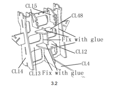
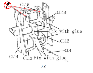
The MDF parts CL15 are the actual parts holding the Wind and Deck Transoms. Below, is image 3.2 from page 9 (instruction manual). At first glance, nothing unusual, but if you pay close attention, parts CL48, CL12, CL13, CL14, and CL4 has to be glued (Fix with glue). However, the image doesn't say 'fix with glue' parts CL15. They MUST NOT be glued!

JigAssembly_Corrections.PNG

I did glue mine :eek: I didn't pay attention. I guess many of us didn't pay attention and glue those parts to CL13. :( If this is the case and you already glue both CL15 it is no big deal, though. But if you have a chance to carefully dissolve the glue and make the parts removable do it! This will save you the hassle later in the build. At the later stages, making CL15 removable plays an important role when you have to release the hull from the berth back and forth. You have been warned!

JigAssembly_CorrectionsEdit.png

Another discovery to follow shortly...stay tuned
 
Attention!!! The below post's conclusion is incorrect. Please read post #381 from Maarten for the correct placement of the part DL3.


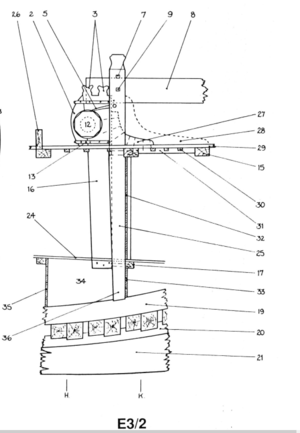
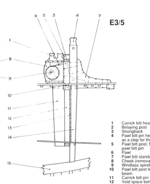
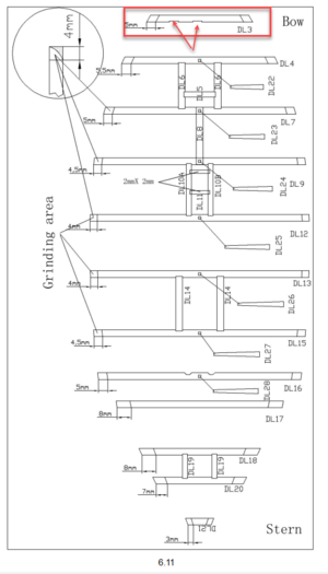
It was bothering me ever since our first discussion about the proper positioning of the lover beam part DL3. Before making the final decision, I decided to look again and compare the AOTS book's drawing with the kit. Apparently, the book doesn't have discrepancies (at least on this part). Please check out both images. I made them side to side for comparison.

1610657709889.png 1610657758737.png

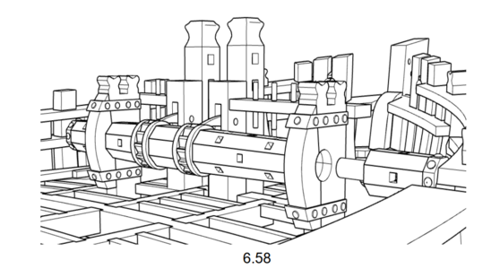
These are two different windlasses. The one on the left side (E3/2) - is the original Windlass. The one on the right side (E3/5) is the modified version. Let's check the modified version first. The biggest change was the introduction of the 'Pawl bit post' (5) fayed and bolted to Pawl bitt pin. The bit post doesn't go all the way to the floor. It is the same hights as the Carrick bitt head. In this windlass configuration the Pawl bitt pins in front of the lover beam (our part DL3). Meaning the notches facing the bow.
On the original windlass, the Pawl bitt pins fayed and bolted to Carrick bitt pin and both approximately the same size and ended at the lower beam. In this configuration, the Pawl bitt pins behind the beam, meaning the notches facing the Stern.
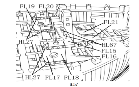
So I check the kit instruction and found on page 42 the image (6.57) of the windlass assembly. It looks like the kit's windlass was designed based on the original configuration and the Pawl bitt pins are behind the beam. The notches should face Stern.

1610658728676.png

1610659265883.png

So this is the incorrect position, At least for our kit. Unless you will build from scratch the modified version of the windlass :cool:

lover_deck_beam.PNG

Next, we will discuss and install Keelson... To be continued and thank you.
 
It was bothering me ever since our first discussion about the proper positioning of the lover beam part DL3. Before making the final decision, I decided to look again and compare the AOTS book's drawing with the kit. Apparently, the book doesn't have discrepancies (at least on this part). Please check out both images. I made them side to side for comparison.

View attachment 205631 View attachment 205632

These are two different windlasses. The one on the left side (E3/2) - is the original Windlass. The one on the right side (E3/5) is the modified version. Let's check the modified version first. The biggest change was the introduction of the 'Pawl bit post' (5) fayed and bolted to Pawl bitt pin. The bit post doesn't go all the way to the floor. It is the same hights as the Carrick bitt head. In this windlass configuration the Pawl bitt pins in front of the lover beam (our part DL3). Meaning the notches facing the bow.
On the original windlass, the Pawl bitt pins fayed and bolted to Carrick bitt pin and both approximately the same size and ended at the lower beam. In this configuration, the Pawl bitt pins behind the beam, meaning the notches facing the Stern.
So I check the kit instruction and found on page 42 the image (6.57) of the windlass assembly. It looks like the kit's windlass was designed based on the original configuration and the Pawl bitt pins are behind the beam. The notches should face Stern.

View attachment 205633

View attachment 205634

So this is the correct position, At least for our kit. Unless you will build from scratch the modified version of the windlass :cool:

View attachment 205635

Next, we will discuss and install Keelson... To be continued and thank you.
I really like the inclusion of perspective drawings which supplement and clarify plan or elevation drawings to better understand what needs to be done. Less frustration and correction revisions which would likely be my own tack. Rich (PT-2)
 
Back
Top