
Very Cool!!!!! Great millwork. RIch (PT-2)Greetings everyone. Many thanks for your valuable comments and 'likes'. Internal structure will require many entry doors, so I took a break from main construction and thought for a moment about doors. There are many different styles of doors but they are all made the same way. I took the door style sample from the AOTS book, and modify to suit my taste.
So let's begin. Doors in the kit provided with panels laser etched, and looks a bit small to the scale. We will be using Pear and boxwood as the main material and will make them a bit bigger to fit the scale. This is not the final design, and it may need more modifications down the road, But I will most likely use the same techniques and material. First, I cut all necessary strips of various dimensions.
View attachment 210266
Started with panels as they require some 'fancy' work. Here is comes handy my ProxxyMill, very happy to have one, it is a great tool.To make those panels 'fancy,' I made a simple jig.
View attachment 210267
The round bur is used as the router bit, Stock of wood slides against the jigs border while the bur removes the wood. Start with a touch of the edge of the wood and slide until fully complete. Before lowering the burr, switch to another side and complete it. Now lower the burr, but don't lower too much, it is better to remove a small amount in one pass. Choose alternative sides until you are happy with a result.
View attachment 210268View attachment 210270
View attachment 210296
Pretty cool, right? The stock panels already 'fancy', but I made a further decision to make it even fancier. I found a very small star endmill, and use it to make a small grove on top. The process of removing wood is the same as for the round bur.
View attachment 210271
Here you go...now the panel looks real 'fancy' and the actual door is ready to be assembled. The door frame consists of the top rail, bottom rail, lock rail, hinge stile, and lock stile. All parts were cut by size and assembled using a flat surface (ceramic tile in my case) and machinist square.
View attachment 210276 View attachment 210277
First, all rails glued to the hinge stile. Once the glue is set, the lock stile is glued. Use machinist square to control squareness across the board. Once all dried, the door\s ready to sand. 320 grit paper was used follow the 400 grit.
View attachment 210282 View attachment 210283
...and here are the doors
View attachment 210284
View attachment 210298
The left one made out of boxwood, both the middle doors made with boxwood panels and Pear rails and stiles. The right one was made out of Pear. The supervisor made inspections.
View attachment 210299
I think he is happy with the result...thus far.
Thank you all, to be continued...

-

SUBSCRIBE TO SHIPS IN SCALE TODAY!
The beloved Ships in Scale Magazine is back and charting a new course for 2026!
Discover new skills, new techniques, and new inspirations in every issue.
NOTE THAT OUR NEXT ISSUE WILL BE July/August 2026 -

Win a Free Custom Engraved Brass Coin!!!
As a way to introduce our brass coins to the community, we will raffle off a free coin during the month of August. Follow link ABOVE for instructions for entering.
- Home
- Forums
- Ships of Scale Group Builds and Projects
- HMS Alert 1777 1:48 PoF Group Build
- HMS Alert 1777 1:48 Group Build Logs
You are using an out of date browser. It may not display this or other websites correctly.
You should upgrade or use an alternative browser.
You should upgrade or use an alternative browser.


Your doors are stupidly awesome!! I think you and Maarten could make a killing on upgrade kits ( but I suspect that the effort could never be costed!) Well done.
You will definately have to make an open cut to see it all ( its solid enough once the hull is fully assembled and could easily have ribs cut and cross joined towards the end after fit out). Your skill and patience blows me away!
You will definately have to make an open cut to see it all ( its solid enough once the hull is fully assembled and could easily have ribs cut and cross joined towards the end after fit out). Your skill and patience blows me away!

Many thanks, Paul! Love the way you evaluate the make of doors. While most internal work will not be seen (true), it just an extra joy to know the work we did is there. Also, I was hoping that the method of making doors would help others in their own builds of various models.Your doors are stupidly awesome!! I think you and Maarten could make a killing on upgrade kits ( but I suspect that the effort could never be costed!) Well done.
You will definately have to make an open cut to see it all ( its solid enough once the hull is fully assembled and could easily have ribs cut and cross joined towards the end after fit out). Your skill and patience blows me away!
Most-likely will not cut the ribs, furthermore, thinking more towards planking one side (internal\external) the same way as Maarten did. Thanks again, Mon Amie
I will do something like that, hope to show more about it in the coming two weeks.Your doors are stupidly awesome!! I think you and Maarten could make a killing on upgrade kits ( but I suspect that the effort could never be costed!) Well done.
You will definately have to make an open cut to see it all ( its solid enough once the hull is fully assembled and could easily have ribs cut and cross joined towards the end after fit out). Your skill and patience blows me away!
Greetings everyone, I hope to find all of you in a good health and great spirit! As always, first, I'd like to express my gratitude to all readers, those who comment and express their emotions thru 'likes' ")
Assembly slowly moving and today we will talk about Limber strake and Mainmast step. But before we will dive into details we have to prepare the berth by adding support for Thickstuff over the first futtock heads, the Thickstuff over the second futtock heads, and Deck clamp & beam shelf.
The support parts are made from MDF and labeled CL19 thru CL45 in our kit. I hope you have labeled them before cut from the boards, while they technically look the same, they are not. They have to be installed according to diagram 6.2 from our instruction manual on page 25.

The kitt supplies the basswood dowels of 3mm (wood bar on the diagram), this must be cut in pieces of 6mm long. I use my miniature miter saw and prepared as noted.


The installation is rather cumbersome and required some patience and creativity. There is not much space for your fingers\hands to move especially at the bottom of the hull. DO NOT glue either part. I recommend removing laser char just a bit, so the dowels inserted with pressure. First, install all the dowels into the parts themselves (like on the image above), and then in corresponding stations. Pay close attention to what side of the CL23, CL21, and CL19 the parts are installed. You may well call to mind all your 'cursing' vocabulary, but in the end, you will be rewarded with great jigs helping to position the Thickstuff and Deck clamp strips evenly.
Alright, let's move on. Very good reference material to get familiar with all the parts we will deal with is the AOTS book. Check the image below 'Hull construction', it depicts all the structured parts internal as well as external. Take a look at part 19, this is the Limber strake.

Limber strake (nautical) - The first course of inside planking next to the keelson. Gutters or conduits on each side of the keelson to afford a passage for water to the pump well.
In our kit, the Limber strakes represented by parts DL01 and DL02. This part has a groove for Limber boards (not included in the kit), the grove must be position towards the keelson. It is also suggested to install the Mainmast step.

Check number 5 on the reference image above. Yes, you are correct, it is the Limber strake, and the number 2 is the mainmast step. In the kit, the mast step represents by three parts gluing together (2 x BL35 and BL36). Pay attention when gluing together BL36 going inside surrounded by BL35.

Here is the ready part


in order to accept the Libmer strakes tight and nice, you must carefully clean the edges with a sharp knife. You can achieve this by trim & trial process. The Limber stake must snug into the grove like so (below). Also, you may represent the correct 'mast foot' it should be cut with a slight angle (#3 in the reference image)


You may notice the holes predrilled to accept the bolts. I will be using the same method of bolt imitation as I use to fastened keelson to the keel. Actually, the supervisor (still on probation) carefully checks bolts in order to approve.


Using the stem\stern keelson's knee notches, and the mast step as the reference we position and glue the first limber strake to the hull. Use only drops of glue to each frame. You don't want excessive glue spread to the outside of the frame. It will be hard to clean. Also, do not glue the mast step. After the glue completely dried, we predrill the holes for 0.6mm brass wire so we can imitate bolts. Before bolts are inserted flash with keelson, I use round 'cup bur' to make the head round.


The same procedure used to glue the Limber strake on the opposite side. The length of the limber strake determined based on your own fit and the excess may be cut off.

To be continued...thickstuff are next!
Assembly slowly moving and today we will talk about Limber strake and Mainmast step. But before we will dive into details we have to prepare the berth by adding support for Thickstuff over the first futtock heads, the Thickstuff over the second futtock heads, and Deck clamp & beam shelf.
The support parts are made from MDF and labeled CL19 thru CL45 in our kit. I hope you have labeled them before cut from the boards, while they technically look the same, they are not. They have to be installed according to diagram 6.2 from our instruction manual on page 25.
The kitt supplies the basswood dowels of 3mm (wood bar on the diagram), this must be cut in pieces of 6mm long. I use my miniature miter saw and prepared as noted.
The installation is rather cumbersome and required some patience and creativity. There is not much space for your fingers\hands to move especially at the bottom of the hull. DO NOT glue either part. I recommend removing laser char just a bit, so the dowels inserted with pressure. First, install all the dowels into the parts themselves (like on the image above), and then in corresponding stations. Pay close attention to what side of the CL23, CL21, and CL19 the parts are installed. You may well call to mind all your 'cursing' vocabulary,
but in the end, you will be rewarded with great jigs helping to position the Thickstuff and Deck clamp strips evenly.Alright, let's move on. Very good reference material to get familiar with all the parts we will deal with is the AOTS book. Check the image below 'Hull construction', it depicts all the structured parts internal as well as external. Take a look at part 19, this is the Limber strake.
Limber strake (nautical) - The first course of inside planking next to the keelson. Gutters or conduits on each side of the keelson to afford a passage for water to the pump well.
In our kit, the Limber strakes represented by parts DL01 and DL02. This part has a groove for Limber boards (not included in the kit), the grove must be position towards the keelson. It is also suggested to install the Mainmast step.
Check number 5 on the reference image above. Yes, you are correct, it is the Limber strake, and the number 2 is the mainmast step. In the kit, the mast step represents by three parts gluing together (2 x BL35 and BL36). Pay attention when gluing together BL36 going inside surrounded by BL35.
Here is the ready part
in order to accept the Libmer strakes tight and nice, you must carefully clean the edges with a sharp knife. You can achieve this by trim & trial process. The Limber stake must snug into the grove like so (below). Also, you may represent the correct 'mast foot' it should be cut with a slight angle (#3 in the reference image)
You may notice the holes predrilled to accept the bolts. I will be using the same method of bolt imitation as I use to fastened keelson to the keel. Actually, the supervisor (still on probation) carefully checks bolts in order to approve.
Using the stem\stern keelson's knee notches, and the mast step as the reference we position and glue the first limber strake to the hull. Use only drops of glue to each frame. You don't want excessive glue spread to the outside of the frame. It will be hard to clean. Also, do not glue the mast step. After the glue completely dried, we predrill the holes for 0.6mm brass wire so we can imitate bolts. Before bolts are inserted flash with keelson, I use round 'cup bur' to make the head round.
The same procedure used to glue the Limber strake on the opposite side. The length of the limber strake determined based on your own fit and the excess may be cut off.
To be continued...thickstuff are next!
...continued from the above post.
The next step to install Thickstuff over the first futtock heads. Those parts (DL30) in the kit and can be located on timber board #20, They are pre-scored for easy handling, however, fragile and will require extra caution when positioning in the hull. I recommend soaking in warm water for few minutes before handling.
Both ends (Stem and Stern) must be trimmed according to your hull's shape. At the bow section, the thickstuff starts at the beginning of the keelson and ends a bit further after Crutch precisely at the keelson first scarf joint. The trimming process required multiple times positioning\removing the part until it perfectly fits. Please note, the thickstuff parts must freely lay on the frames without any resistance (spring effect), use the first bottom jig parts as the guide. Only after you satisfy with the fit placement, proceed with glue.


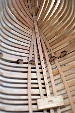
Both thickstuff installed and bolted. The Stern section below.

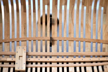
The bow section


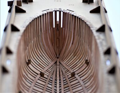
Next will be installing the Thickstuff over the second futtock heads. It will be also a placeholder for lover deck beams. Again, a word of caution. The timber is really fragile, take extra care when trimming\adjusting the fit. Don't forget to soak in warm water. This Thickstuff will start from the upper notch of the second breasthook.


Some macro details


To be continued...
The next step to install Thickstuff over the first futtock heads. Those parts (DL30) in the kit and can be located on timber board #20, They are pre-scored for easy handling, however, fragile and will require extra caution when positioning in the hull. I recommend soaking in warm water for few minutes before handling.
Both ends (Stem and Stern) must be trimmed according to your hull's shape. At the bow section, the thickstuff starts at the beginning of the keelson and ends a bit further after Crutch precisely at the keelson first scarf joint. The trimming process required multiple times positioning\removing the part until it perfectly fits. Please note, the thickstuff parts must freely lay on the frames without any resistance (spring effect), use the first bottom jig parts as the guide. Only after you satisfy with the fit placement, proceed with glue.
Both thickstuff installed and bolted. The Stern section below.
The bow section
Next will be installing the Thickstuff over the second futtock heads. It will be also a placeholder for lover deck beams. Again, a word of caution. The timber is really fragile, take extra care when trimming\adjusting the fit. Don't forget to soak in warm water. This Thickstuff will start from the upper notch of the second breasthook.
Some macro details
To be continued...
Attachments

Hi Jim, very neat work. A trip to memory lane .
Did you oil these parts already, the colours are warm?
.Did you oil these parts already, the colours are warm?
Thanks, Mon Amie. Yes...something you made not that far. I Will be using your build for the footwaling and ceiling planking. In the last 5~6 images I use white spirit to show off the timber color, It is not oiled yet...Hi Jim, very neat work. A trip to memory lane
Did you oil these parts already, the colours are warm?
Oh the joyous memories those supports bring back!!!!!.
Great work as usual. BTW the 2 parter is the bowsprit and I'm using the others as the ladders.Tks
Great work as usual. BTW the 2 parter is the bowsprit and I'm using the others as the ladders.Tks
Thanks, Paul. I scratched the hands and my fingers were swollen, ouch...but I have to say, those are big help while positioning and warrant for the accurate placement.Oh the joyous memories those supports bring back!!!!!.
Looking very good and well explained with very informative photos
-> A very good tutorial for my later work on the Alert, as soon the Le Coureur is finished
-> A very good tutorial for my later work on the Alert, as soon the Le Coureur is finished

I'll also use Jimsky and this thread as mentor and sensei for my Alert build (if I ever finish Le Coureur that isA very good tutorial for my later work on the Alert, as soon the Le Coureur is finished
) but for sure also several of the other Alert group builders I'll use the same way.Everything Jimsky makes is just so annoyingly perfect so when my falcon eyes for the very first time spots a minor flaw I'll certainly not let the chance slip away of some friendly affectionate bullying (Jimsky can take it). For this part I will pay slightly more attention to Maarten's build:

Oh...yes, Poul! You are correct! You spotted one of many flaws I let go as is.Everything Jimsky makes is just so annoyingly perfect so when my falcon eyes for the very first time spots a minor flaw I'll certainly not let the chance slip away of some friendly affectionate bullying (Jimsky can take it). For this part I will pay slightly more attention to Maarten's build:
When I assemble the mainmast step I referenced the AOTS book. Their drawing shows the bolts in a particular order.
...so I simply predrill that way
 Of cause I better check with my layout first before drilling, but I have not... Moving the mast step forward would result in a wrong mast placement. Also, there is a notch in the keelson and protrusion in the mast step so it is installed only one way.
The only way to repair is to make a new one... but I use a very good glue, it bonds very strong, Oh well... I will have to deal with it.
Thank you, my friend. You may change your mind as I have too many flaws, lately. Good thing, our members will spot them so I can correct them.Looking very good and well explained with very informative photos
-> A very good tutorial for my later work on the Alert, as soon the Le Coureur is finished
No worries, once the inner planks are in place nobody will be able to see it
Not seeing this log before, or that my old brain recalls, the work is nicely done and I really like the inclusion of the small ships' surveyor overseeing the work. Nicely done from my pier as well as his eyeball level examination. Rich (PT-2)No worries, once the inner planks are in place nobody will be able to see it
To be honest...... I would leave it like it is.Oh...yes, Poul! You are correct! You spotted one of many flaws I let go as is.
View attachment 213992
...so I simply predrill that way
View attachment 213993
The only way to repair is to make a new one... but I use a very good glue, it bonds very strong, Oh well... I will have to deal with it.
Usually tha mastfoot is on top of the inner planking - so I am pretty sure, that the shipwrights bolted it down whereever the bolt would be, through the frame or sometimes not - it was mainly important, that the mast foot is sitting directly on top of the keelson. Maybe they had some timber filling pieces between the frame floor timbers
I wonder if it was actually bolted at the building berth. Shouldn't theere be an option to fine tune the mast rake after the ship was launched? (to balance the helm)To be honest...... I would leave it like it is.
Usually tha mastfoot is on top of the inner planking - so I am pretty sure, that the shipwrights bolted it down whereever the bolt would be, through the frame or sometimes not - it was mainly important, that the mast foot is sitting directly on top of the keelson. Maybe they had some timber filling pieces between the frame floor timbers
I am maybe wrong, but I guess the total weight with the mast inside the foot would not allow to move this system or finetune the location along the keelson.I wonder if it was actually bolted at the building berth. Shouldn't theere be an option to fine tune the mast rake after the ship was launched? (to balance the helm)
Maybe only when the ships were partly dismantled during their large repair or refitting - than sometimes the masts were lifted out and the fott could be adjusted.
...it is possible to balance the helm by tilting the mast (either way)?Shouldn't theere be an option to fine tune the mast rake after the ship was launched? (to balance the helm)