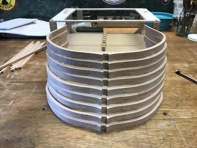
Mike not after crazy accuracy on this as it’s my first but if I can add something without too much extra work I will. This is a big project for me but I’m enjoying it immensely compared to the Fly kit I had started. Yes I’d be interested but have a long long way to go on this one first. ThanksHi Tony, if you would like to build a more accurate model, I would recommend the book The Sailing Man-Of -War 1650-1850 it contains most of the design parameters used for this ship. It is a good idea to do your own research before starting a scratch model.
We are currently working on a more advanced cross section of the HMS Ontario you may be interested in.
View attachment 242671
-

Win a Free Custom Engraved Brass Coin!!!
As a way to introduce our brass coins to the community, we will raffle off a free coin during the month of August. Follow link ABOVE for instructions for entering.
-

PRE-ORDER SHIPS IN SCALE TODAY!
The beloved Ships in Scale Magazine is back and charting a new course for 2026!
Discover new skills, new techniques, and new inspirations in every issue.
NOTE THAT OUR FIRST ISSUE WILL BE JAN/FEB 2026
- Home
- Forums
- Ships of Scale Group Builds and Projects
- Group Build Archives
- Blandford Cross Section PoF Group Build
You are using an out of date browser. It may not display this or other websites correctly.
You should upgrade or use an alternative browser.
You should upgrade or use an alternative browser.
- Joined
- Apr 20, 2020
- Messages
- 6,255
- Points
- 738

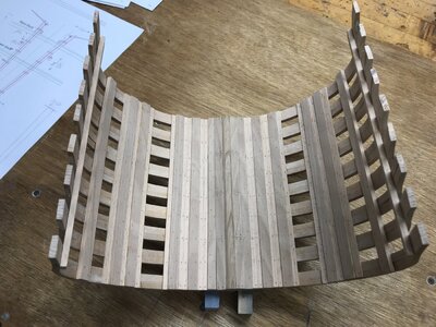
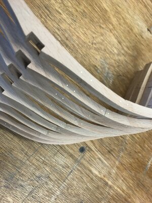
the frames looks greatDrilled and pinned the frames. Took all day but it’s done. I don’t mind the brass color here at all.
View attachment 242676View attachment 242677
Very accurate and fine work - very good work
Thanks guys. Not much progress tday. Just going to cut the spacers for the tops of the frames. Using pine I had here as they won’t be seen when done. Still have to fair the frames prior to actually gluing and pinning them to the keel. Have to double check my rabbet too, make sure a plank edge sits in it properly. It’ll be slow going the next few days. A lot of work with little to show for it but that’s modeling.
Last edited:
Ok guys. Important question for those that know more than I which is everyone ! I finally got the frames all set and “squared” up. I think. It may be hard to see in the pics but my deck clamp marks are not all spot on. Is this to be expected since they came from the drawings and the frames being cut out are not exact ?? Also one thing confusing me is how do I go about making sure the frames are all set properly ? I feel I have it at this point but I ’ve seen people use levels and plumb bobs but I assume measuring off a fixed surface will do the same thing. I’m having difficulty figuring out how to establish measuring points especially for the frame tops or isn’t it that critical ? Am I over thinking it ? Ill be looking the plans over so see what I can glean from them. Thanks
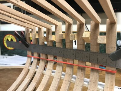
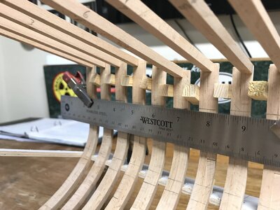
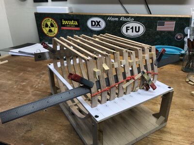
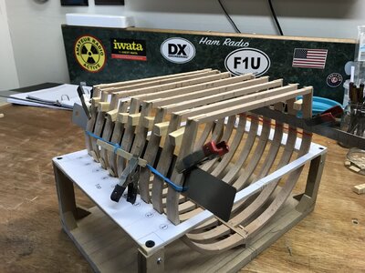


in real shipbuilding the keel is laid first because everything else is referenced from that baseline. The bottom of the keel sits on the base of the jig. Use the jig bottom as your first point of reference. The deck clamps are critical. Get them right! Use the plans to figure out how far above the jig base they’re located. Find those points aft, forward and in the middle. They should form a straight line the may be slightly sloped downward moving forward, if I recall. Don’t worry too much about the frame tops. You’ll have to trim the bulwarks later!
Relax and have fun! It’s only wood, and you are doing a fantastic job!
Relax and have fun! It’s only wood, and you are doing a fantastic job!
Thanks Doc, Yes I am measuring off the build board. its no problem drawing the deck clamp locations Id assume that if fore and aft are on the money going straight across will be correct ? As for the frame tops I'm obsessed with cutting them asap because they're critical and a screw up there after much much more work is put in would be a huge set back, that's my OCD talkingin real shipbuilding the keel is laid first because everything else is referenced from that baseline. The bottom of the keel sits on the base of the jig. Use the jig bottom as your first point of reference. The deck clamps are critical. Get them right! Use the plans to figure out how far above the jig base they’re located. Find those points aft, forward and in the middle. They should form a straight line the may be slightly sloped downward moving forward, if I recall. Don’t worry too much about the frame tops. You’ll have to trim the bulwarks later!
Relax and have fun! It’s only wood, and you are doing a fantastic job!
- Joined
- Aug 10, 2017
- Messages
- 1,706
- Points
- 538

Hi Tony, your assumption for the location of the deck clamps is correct, they are in a straight line fore and aft. As Doc said don’t worry about the frame tops they will be trimmed later in the build, check a few of the completed build logs for examples.
OK Mike yes I will. I have the deck clamps marked after checking and rechecking many times. Measured the plan clamp tops and marked it out as close as possible. I'm ready to glue the frames to the keel.... I hope. ThanksHi Tony, your assumption for the location of the deck clamps is correct, they are in a straight line fore and aft. As Doc said don’t worry about the frame tops they will be trimmed later in the build, check a few of the completed build logs for examples.
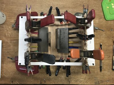
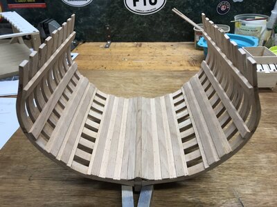
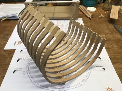
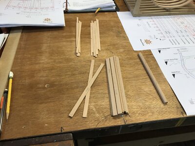
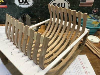
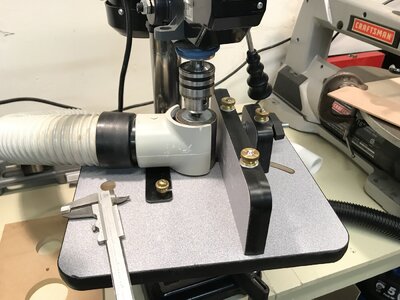
Glued and pinned the frames to the keel and glued the spacers between the frames yesterday. Measured and marked finally the frame tops and deck clamps. Today managed to cut the keelson, strakes, limbers, foot walls and deck clamps out of my stock. Freed the frame of its confines to cut the frame tops and for a quick sand which I’m sure will be done again later. I highly recommend the Luthiers Friend thickness sander. It’s fantastic for taking off that 1/16 or so. Now I have it I wouldn’t be without it.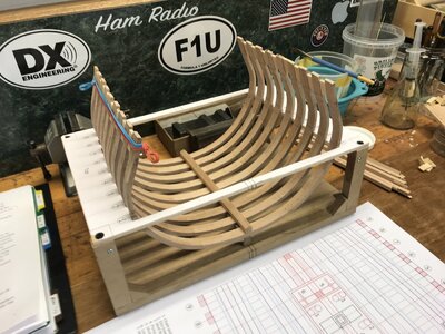


Last edited by a moderator:
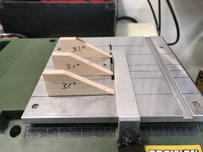
Ok so far. That’s how I cut the 31 degree on the limber boards.
Questions.
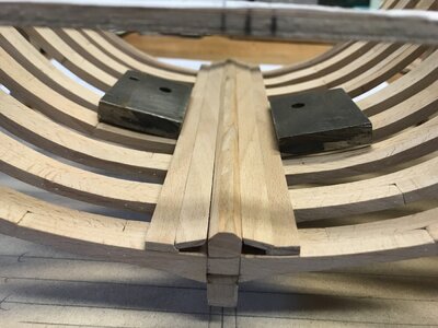
Did the inner hold boards, strakes, foot walling etc in fact have caulking between them ? Also Doc I see your limber boards are separated into shorter boards. Is this artistic license ? I haven’t seen either the caulking or limber boards like that in my books or anywhere else. I’m ready to start the hold work now and don’t want to get ahead of myself. Thanks
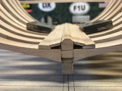
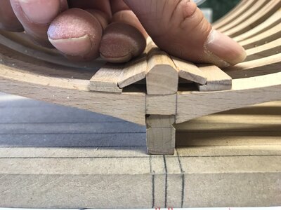


Last edited by a moderator:
In general I don't think the planking in the hull was caulked, but adding it is acceptable artistic license: It shows off the individual planks, so I tend to do it!
Regarding the limber boards: The purpose of the limber passage was to drain water to the lowest point of the bilge so the pumps could remove it. The limber boards allow access to that space to remove any debris and also to help prevent debris from getting in there in the first place. In general they were short (*about 3 feet long) so they could be handled by one seaman, and had two finger holes drilled in each to allow for gripping them. The quote below is from Goodwin's book on the construction of the English Man of War:
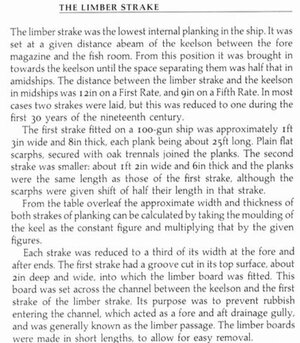
Regarding the limber boards: The purpose of the limber passage was to drain water to the lowest point of the bilge so the pumps could remove it. The limber boards allow access to that space to remove any debris and also to help prevent debris from getting in there in the first place. In general they were short (*about 3 feet long) so they could be handled by one seaman, and had two finger holes drilled in each to allow for gripping them. The quote below is from Goodwin's book on the construction of the English Man of War:

Ok Doc yes that all makes sense that’s how I thought it was but didn’t find any info on it. I did like you did made the limber in 4 sections. Well not really, simulated it. I put tree nails in but it’s staying that way, not cutting two more limber boards ! The toothpick system works well, the dye didn’t penetrate and after sanding there’s a light center but then again treenails were wood not dark like bolts. Dying more now as I see I’ll need a lot. Thanks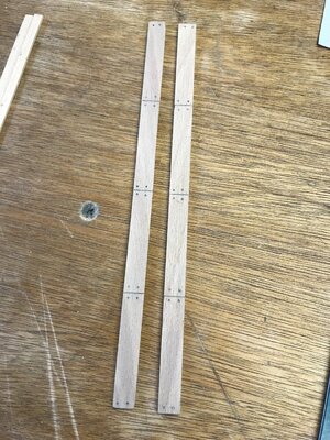

Last edited by a moderator:
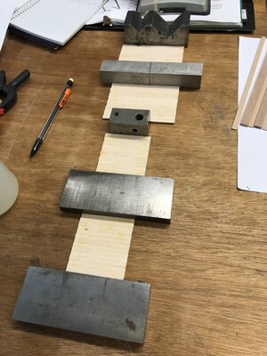
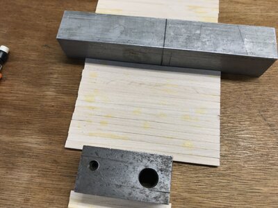
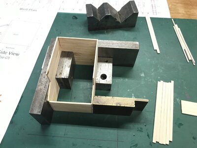
Yes indeed milling lumber and surfacing is time consuming. Been playing around with the well and shot locker. Used the Maple for it. Mistake ? I’m not sure. I didn’t caulk it and should have I think. Made the mast step. Also finished all the hold timbers. It’s all just dry fitted now. Once the well/locker is done I’ll move onto the pumps etc. Thinking about how I’ll do the caulking from here on out. Recommendations ?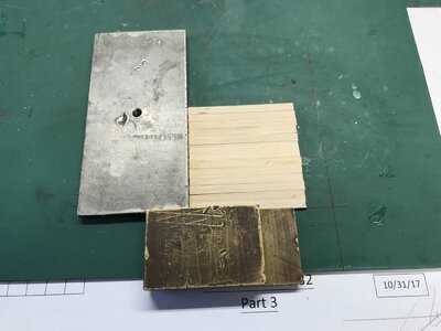
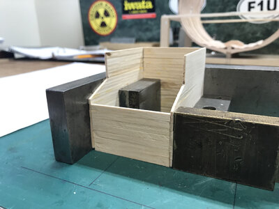
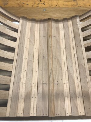
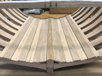
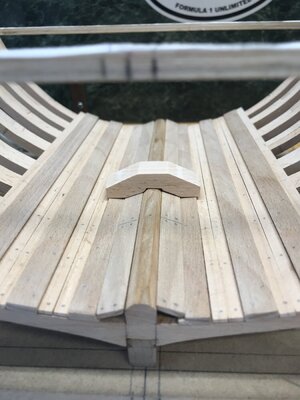


Last edited by a moderator:
- Joined
- Apr 20, 2020
- Messages
- 6,255
- Points
- 738

very niceYes indeed milling lumber and surfacing is time consuming. Been playing around with the well and shot locker. Used the Maple for it. Mistake ? I’m not sure. I didn’t caulk it and should have I think. Made the mast step. Also finished all the hold timbers. It’s all just dry fitted now. Once the well/locker is done I’ll move onto the pumps etc. Thinking about how I’ll do the caulking from here on out. Recommendations ?

Coming along nicely !
Donald
Donald
Thanks all for the comments and especially the advice and help. I’ll be asking many many more questions.
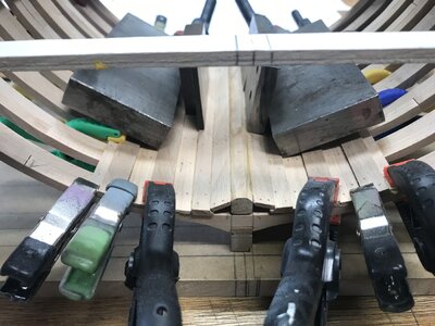
Progress on the well and moved ahead and installed the limber, strakes and foot walling. Clamped everything I could while doing to keep the structure straight. Important Question. I went over the logs today again. The pumps. How long did you guys make them ???
I didn’t see any pics of the pumps below decks. AOTS pics here. I saw nothing like this, all these below deck structures in the logs. I see some used drilled out tapered stock and some made the elm tree pumps from slats. I see which will be easier but I’m still debating using slats. Give it a shot anyway and see what happens.
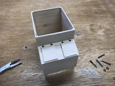
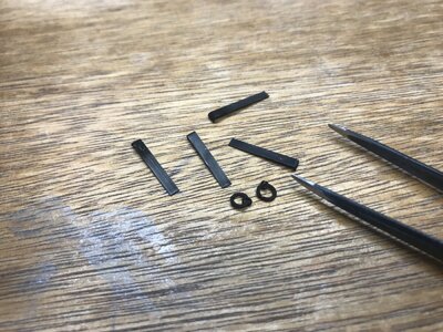
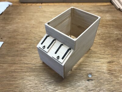
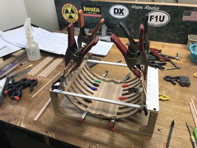
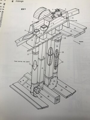
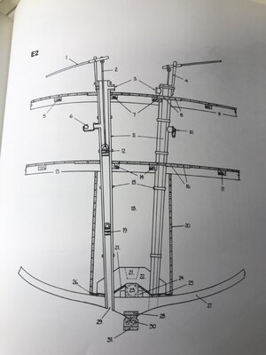
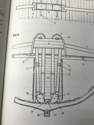
Thanks
I didn’t see any pics of the pumps below decks. AOTS pics here. I saw nothing like this, all these below deck structures in the logs. I see some used drilled out tapered stock and some made the elm tree pumps from slats. I see which will be easier but I’m still debating using slats. Give it a shot anyway and see what happens.


Thanks
Last edited:
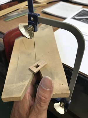
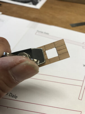
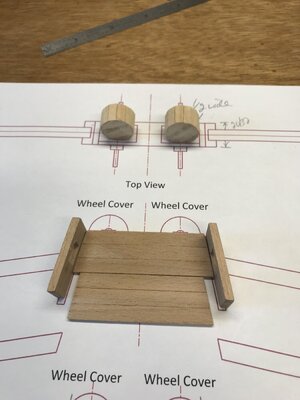
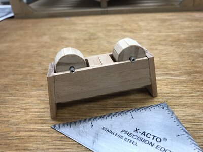
Chain pump done. I’m at a crossroads with the Elm tree pumps. Do they in fact go through all the levels ?? I haven’t seen pics in the logs of this really. What’s the consensus ? Did you guys make them full length and also the chain pumps did any of you build the below deck parts ? Finally got the hold planked. Ready to start on the lower deck parts, I think.
