• Beginning at 5:00AM PST (13:00 UTC) on Friday February 14th, all services in the Los Angeles, California, USA Data Center will be offline to perform a Data Center Migration. Due to the nature of this migration, we anticipate up to 24 hours of downtime to safely complete this work. Please be patient during this time and thank you for being a valuable member of our community.

USRC Harriet Lane Model Shipways 1:96 scale circa 1863

Chuck, Nice work as usual!

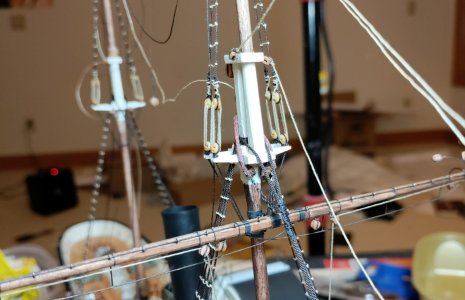
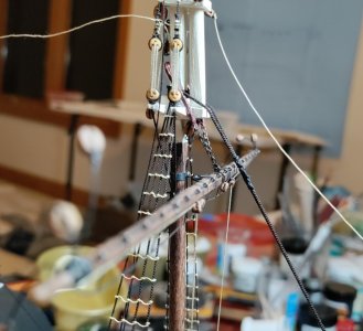
I believe that the reason for leaving he ratlines off the main topmast is that there are no square sails here; only the gaff topsail. I also believe that this sail could be set without climbing the topmast. I don’t have time at the moment but I’ll do some checking later today.

Roger
Roger is right about the top sails. It’s also on the schooners like the Bluenose. On that ship were only a few ratlines till the height where the lowered topsails with the mast hoops where collected. And on the main mast a few more then on the fore mast. To then temporarily tie them together with a line. But on your fore mast there is a square sail.
And I think that the gaff sails on your Harriet Lane were lowered to the fore mast.
Regards, Peter
Darn it Roger and Peter! Why weren't you answering my questions before I spent two hours putting unnecessary and inaccurate ratlines on the main top mast shrouds!!! ROTF

I get it that the absence of square sails and the locations of the working parts didn't require ratlines. But there is other stuff up there that might need servicing at some point. Right? The lower and upper forestays? Oh well. Better research next time - an maybe, like "measure twice cut once", ask questions and wait for the answers! So much patience!

Thank you both so much for your input. Now the question is whether to remove the ratlines from the main topmast shrouds. :eek: I don't think I can do this without stripping the mast and starting over. :eek::eek::eek: I used a health amount of matte acrylic medium on my very tight knots.

And he declared: "VICTORY!" and moved on.

Blessings.
Chuck
 
Chuck, Nice work as usual!

I believe that the reason for leaving he ratlines off the main topmast is that there are no square sails here; only the gaff topsail. I also believe that this sail could be set without climbing the topmast. I don’t have time at the moment but I’ll do some checking later today.

Roger
I just looked at my Harriet Lane ca. 1863 and I did include ratlines on the main topmast, for no other reason than I was the official Bo'sun on the build and decided I wanted them there incase Murphy got his hands in the rigging. The tri-gaff sail is rigged to be handled from the deck. Contemporary paintings and engravings show the sail furled and reefed to the mast, under way, under steam. I had no rigging plan to show how that sail could be handled from the deck, so I worked it out logically even though you can't see it finished, it's all there, and all works (in theory at least).
I have a friend who had a late 19th c. gaff rigged sloop that, of course, had no rat lines. I remember him telling me how he had to shinny up the mast one day to free some jammed-up mast hoops and gaff jaws. :eek:
Also, you are building your H.L. ca. 1863 and there are no plans for that. A serious departure from her 1850's configuration. The kit plans are useless for kit bashing as extensive as that. With all the research you have invested in yours subsequent to mine, there is considerable difference between the two as well, as one would hope, to much improve the modelling of that valiant ship and crew Jan.1, 1863 at the second battle of Galveston Bay.

Pete
 
Last edited:
Wait for it...
I just looked at my Harriet Lane ca. 1863 and I did include ratlines on the main topmast, for no other reason than I was the official Bo'sun on the build and decided I wanted them there incase Murphy got his hands in the rigging. The tri-gaff sail is rigged to be handled from the deck. Contemporary paintings and engravings show the sail furled and reefed to the mast, under way, under steam. I had no rigging plan to show how that sail could be handled from the deck, so I worked it out logically even though you can't see it finished, it's all there, and all works (in theory at least).
I have a friend who had a late 19th c. gaff rigged sloop that, of course, had no rat lines. I remember him telling me how he had to shinny up the mast one day to free some jammed-up mast hoops and gaff jaws. :eek:
Also, you are building your H.L. ca. 1863 and there are no plans for that. A serious departure from her 1850's configuration. The kit plans are useless for kit bashing as extensive as that. With all the research you have invested in yours subsequent to mine, there is considerable difference between the two as well, as one would hope, to much improve the modelling of that valiant ship and crew Jan.1, 1863 at the second battle of Galveston Bay.

Pete
Pete! Paul! Pete's post made sense of your post, Paul ROTF Like Pete, I thought, if something goes wrong up there are the sailors to shinny up the top mast? Feeling no regrets now! Thank you, Pete!:D

Blessings.
Chuck
 
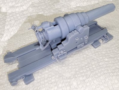
When you're ready to start a model of HMS Warrior, I'll be ready for you. ;)
View attachment 499584
Jerry! Funny you should mention HMS Warrior. I was just talking about her with my Admiral;) That gun looks splendid, Sir! Simply splendid! You really do need to start producing these for sale to select builders for whom only the very finest will do! I'm on board!!!!

Blessings.
Chuck
 
What ho, shipmates!

When a person makes a mistake, they should, in honor, apologize. So, I apologize for making such a fuss about the absence of ratlines on the main topmast. Mea maxima culpa! As you know, I love this kit. There are way too few examples of sidewheel warships. So, God bless @Model Shipways for giving us a 1/96 scale version of Harriet Lane. As you also know, I have been troubled from the start of my build by the way the instructions predict doom if the builder tries to add details that the instructions acknowledge should be there. Moreover, I can't help but wonder about the lack of certain details on the model (or things that are just flat wrong like the position of the ships wheel) when the actual Webb plans are readily available. So, as I progressed through the plans my doubts about the instructions grew and overwhelmed my thinking. Lesson learned. Even where the instructions make one doubtful, there is room to doubt one's doubts. So questions first, more research and patience. I promise!

Thank everyone for sharing their knowledge so generously!

Blessings. Peace. Gratitude.
Chuck
 
Last edited:
When a company designs and offers a kit on the open market, however honorable their intentions are, they have to be aware that the, often very experienced, model builders will
expose the inevitable flaws baked into the kits' design, instructions and plans. Hopefully, such excellent and open-minded companies as Model Shipways (Expo) will take these criticisms, discard the unhelpful, and integrate the useful as improvements to their products.

Pete
 
Chuck,

I especially enjoy following your build of this model, perhaps because I built Model Shipways’ original 1:144 scale version way back in the 1960’s. It’s not in the same league as yours, but sitting in its glass case atop a tall bookcase unavailable to close examination she’s impressive.

The location of the helm is curious. These mid Nineteen Century Revenue Cutters are the earliest vessels that I have seen featuring an enclosed Pilot House. Other side wheel paddlers, were navigated from the bridge spanning the side wheel boxes (hence the name). If the vessel was navigated from the pilot house, how were steering commands relayed to the helmsman at the stern? As Webb clearly shows a steering wheel at the stern, it’s reasonable to assume that this is a secondary helm.

These emergency, hand steered helms are commonly seen on later steamships, but by that time, steam steering engines were used for steering the vessel from the pilot house.. The steering engine was either located in the pilot house or on top of the rudder shaft. The emergency steering wheel was connected to the rudder shaft by a clutch, to be disengaged when not in use. The steering wheel position in the pilot house was transmitted aft to the rudder or steering engine by chains or steel rods.

So, how did Harriett Lane’s steering system work? She would have had a removable mechanical link between the secondary helm at the stern and the rudder shaft, but how was the helm position in the pilot house transmitted aft to the rudder in the absence of a steam steering engine? Ropes? Chains? These would have run under the deck invisible on your model. She must have been a bear to steer!

Roger
Roger, your exhaustive and encyclopedic knowledge of these matters is impressive! I look forward to the times when you share them! Thumbsup :D
Pete
 
Chuck,

I especially enjoy following your build of this model, perhaps because I built Model Shipways’ original 1:144 scale version way back in the 1960’s. It’s not in the same league as yours, but sitting in its glass case atop a tall bookcase unavailable to close examination she’s impressive.

The location of the helm is curious. These mid Nineteen Century Revenue Cutters are the earliest vessels that I have seen featuring an enclosed Pilot House. Other side wheel paddlers, were navigated from the bridge spanning the side wheel boxes (hence the name). If the vessel was navigated from the pilot house, how were steering commands relayed to the helmsman at the stern? As Webb clearly shows a steering wheel at the stern, it’s reasonable to assume that this is a secondary helm.

These emergency, hand steered helms are commonly seen on later steamships, but by that time, steam steering engines were used for steering the vessel from the pilot house.. The steering engine was either located in the pilot house or on top of the rudder shaft. The emergency steering wheel was connected to the rudder shaft by a clutch, to be disengaged when not in use. The steering wheel position in the pilot house was transmitted aft to the rudder or steering engine by chains or steel rods.

So, how did Harriett Lane’s steering system work? She would have had a removable mechanical link between the secondary helm at the stern and the rudder shaft, but how was the helm position in the pilot house transmitted aft to the rudder in the absence of a steam steering engine? Ropes? Chains? These would have run under the deck invisible on your model. She must have been a bear to steer!

Roger
Roger! It's like you were there standing at Webb's shoulder as he drew up the plans for Harriet Lane! Thank you!!!

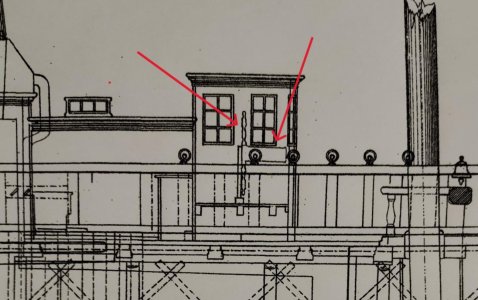
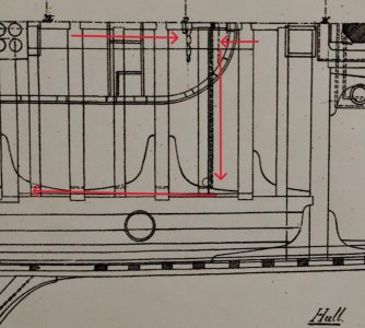
After reading your post, I went to the shipyard and inspected the Webb plans very carefully. When I first "studied" them, I thought there was just some ornamental decoration on the pilot house. I also saw some curious lines running from the pilot house aft to meet up with what I could clearly see as the ropes running from the ship's wheel to the rudder head. Now I see that the ornamental decoration is the profile of the wheel in the pilot house. And those curious lines are ropes. In pic 1 you can make out the wheel profile and a drum for the rope. Pics 2 and 3 show a cutaway of the deck from above and you can see the ropes running aft and the steering arrangement from the second wheel to the rudderhead. In pic 3 the red arrows trace the steering rope path from the pilothouse aft. The yellow arrows show the path starting from the aft wheel.

You might be able to see it, but I can't make out a clutch mechanism to switch from forward to aft steering, or the reverse. Is it possible that both wheels were working at the same time?

Pilothouse 1.jpgPilothouse 2.jpgSteering overhead.jpg

Blessings.
Chuck
 
What ho, shipmates!

I am again busy not following the instructions. Even before I crossed the lower fore yard, I should have set up all of the standing rigging. If I had followed the instructions, all of that standing rigging would be in the way of my fingers as I work of the details of slinging all of the foremast yards. So, the remainder of the standing rigging will have to wait for me to crossing all of the yards.

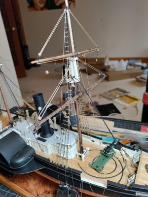
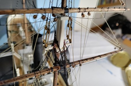
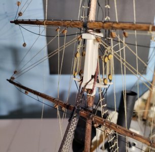
In post #551, I showed the fore lower yard crossed with the chain showing the weight of the yard and declared victory. As I continued working up the mast, I decided to run the lifts through the proper blocks because all of that line was really getting in the way. By happy accident, once the lifts were under strain, they lifted the fore lower yard and the chain sling lost all of its tension. :eek: Not to worry friends, this can and will be fixed! A couple of pics.

Crossing yards 1.jpgCrossing yards 2.jpg
 
Last edited:
If only the designers and maintainers of ships from 150 plus years ago knew the importance of saving drawings and guidance on why they did something an not others, then we wouldn't be having to try to decide what is right or proper for ships in a period of time.
Too right! But, as we know, that's part of the fun!
 
All yards are crossed! The slack lower yard sling is no longer slack! On the other hand, I'm gong to have to raise the T'Gallant yard by about a scale foot, otherwise the inner forestay will have to pass through, rather than under the foot ropes :eek: .

I'll post the pictures after I've had my grog ration.

Blessings.
 
What ho, shipmates!

You do realize that a grog ration involves 8 ounces of navy strength rum. At least based on the great writings of Patrick O'Brien.

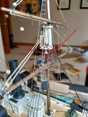
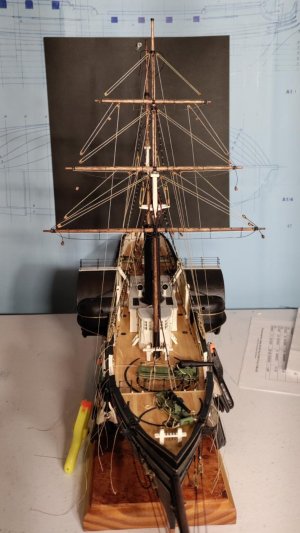
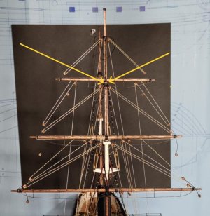
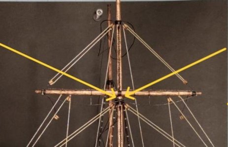
Here are the pics. Pic 1 gives a general idea of what she'll look like once all of the lines are belayed. I don't have the fore tack lines set up on the lower yard yet. I mentioned the T'Gallant yard problem last night. See pics 2 and 3 and follow the yellow arrows. Pics 4 and 5 show that I have no slack in my chain sling now;)

Yards crossed.jpgYards crossed detail.jpg
Yards crossed super detail.jpg
Chain sling slung 1.jpgchain sling slung 2.jpg
 
What ho, shipmates!

You do realize that a grog ration involves 8 ounces of navy strength rum. At least based on the great writings of Patrick O'Brien.

Here are the pics. Pic 1 gives a general idea of what she'll look like once all of the lines are belayed. I don't have the fore tack lines set up on the lower yard yet. I mentioned the T'Gallant yard problem last night. See pics 2 and 3 and follow the yellow arrows. Pics 4 and 5 show that I have no slack in my chain sling now;)

View attachment 500109View attachment 500108
View attachment 500112
View attachment 500111View attachment 500110
That is gonna be an impressive piece of rigging, Chuck.
Regards, Peter
 
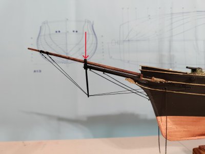
Before I make it difficult for myself, which will happen this evening, when did US Navy ships start flying the Ensign forward - see the red arrow. I'd like to put one here if there is any argument to be made for it.

Blessings.
Chuck

Ensign staff.jpg
 
Back
Top