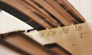
Uwe ladies nail files are good for removing char, and cheap.( The paper type, not the steel ones)
-

Win a Free Custom Engraved Brass Coin!!!
As a way to introduce our brass coins to the community, we will raffle off a free coin during the month of August. Follow link ABOVE for instructions for entering.
-

PRE-ORDER SHIPS IN SCALE TODAY!
The beloved Ships in Scale Magazine is back and charting a new course for 2026!
Discover new skills, new techniques, and new inspirations in every issue.
NOTE THAT OUR FIRST ISSUE WILL BE JAN/FEB 2026
You are using an out of date browser. It may not display this or other websites correctly.
You should upgrade or use an alternative browser.
You should upgrade or use an alternative browser.
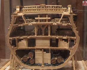
USS BONHOMME RICHARD - POF - Cross Section in Pear - 1:48 - by Uwe
I will give it a try - thanks for the hintUwe ladies nail files are good for removing char, and cheap.( The paper type, not the steel ones)
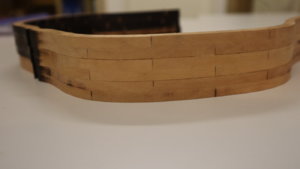
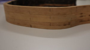
I checked the joints of the second frame and it is better - not good, but better
on the top the second one
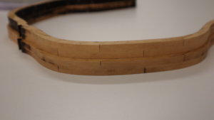
and a closer look
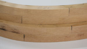
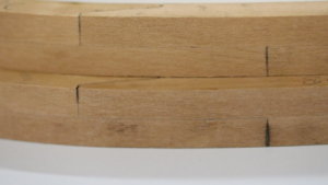
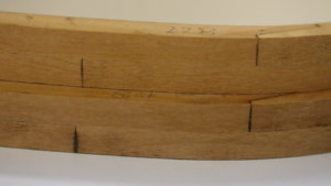
Yesterday I spent 2 hours for preparing the third frame - and I tried even more sanding away the char - the real problem here is the type of the joint with these flat scarf joints. You have to be very careful in sanding, only so much on every part, that they still fit together. A normal butt joint would be much easier to prepare.
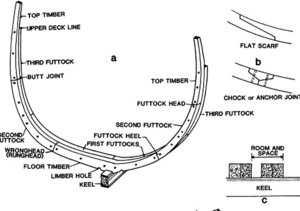
To be honest, with 2 hours work per frame, I could also cut them scratched with my scroll saw -
Maybe the manufacturer should start to combine in their kits laser cut parts and also cnc-cut parts (for elements where laser char is a pain)
on the top the second one

and a closer look


Yesterday I spent 2 hours for preparing the third frame - and I tried even more sanding away the char - the real problem here is the type of the joint with these flat scarf joints. You have to be very careful in sanding, only so much on every part, that they still fit together. A normal butt joint would be much easier to prepare.

To be honest, with 2 hours work per frame, I could also cut them scratched with my scroll saw -
Maybe the manufacturer should start to combine in their kits laser cut parts and also cnc-cut parts (for elements where laser char is a pain)
Very good model - so you put the level now very high for my builtHi, Uwek!
Several years ago I've built this model. The kit was not very detailed, but the result looks not so bad)))
We will see, how my section will look like at the end
Sure it will be better!!!Very good model - so you put the level now very high for my built
We will see, how my section will look like at the end
One advise meanwhile - try to avoid using the photoetched parts from the kit - make yours parts using wire etc
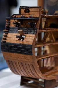
G'day koreets, that is a very nice model of the cross section you have built,
best regards John,
best regards John,
Last edited:
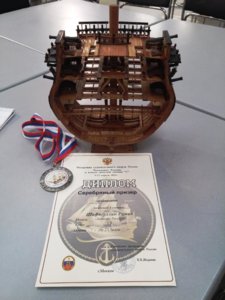
For those who interested. One of the photos from Koreets (Roman) was an award: a diploma and silver medal for his section model presented in 2015 when he participated in the Russian Championship. Bravo!!Hi, Uwek!
Several years ago I've built this model. The kit was not very detailed, but the result looks not so bad)))
Uwe, sorry to higjack your thread.
Sure it will be better!!!
One advise meanwhile - try to avoid using the photoetched parts from the kit - make yours parts using wire etc
KoreetsSure it will be better!!!
One advise meanwhile - try to avoid using the photoetched parts from the kit - make yours parts using wire etc
Excellent looking model. Can you please advise what you used for the trenails?
Thanks
John
No problem, I am happy, that there is some talks in this topic....For those who interested. One of the photos from Koreets (Roman) was an award: a diploma and silver medal for his section model presented in 2015 when he participated in the Russian Championship. Bravo!!
Uwe, sorry to higjack your thread.
Because I realized the medal, I mentioned, that the necessary level for me is high now -
@Koreets ,
thanks for the tipp with the photoetched parts - I will see, what can be done
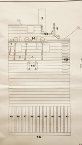
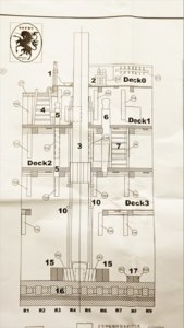
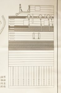
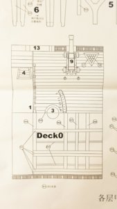
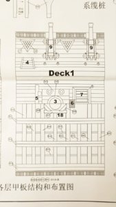
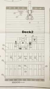
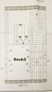
Yesterday I showed some excerpts of the kit drawings, but I forgot to show the cross section of the model - not shown is the internal construction (add-on of the kit)
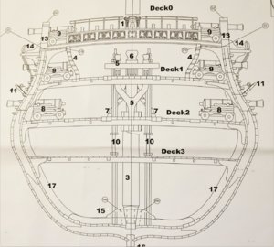
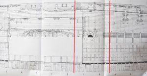
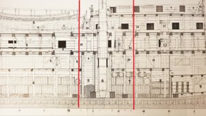
And in the following the excerpts of the Bonhomme Richard drawings from the Boudriot monographie, in which I marked the part of the section with red lines
Sorry, that the photos have a different scale / size.......

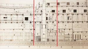
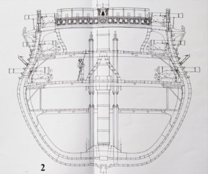
And the cross-section - It is obvious, that several details were changed or adopted - f.e. the hanging knees, thickness of the inner planking.
I will see, how much I will adjust the kit in order to get closer to the planset "version"........
Many Thanks for your interest ..... to be continued ......

And in the following the excerpts of the Bonhomme Richard drawings from the Boudriot monographie, in which I marked the part of the section with red lines
Sorry, that the photos have a different scale / size.......


And the cross-section - It is obvious, that several details were changed or adopted - f.e. the hanging knees, thickness of the inner planking.
I will see, how much I will adjust the kit in order to get closer to the planset "version"........

Many Thanks for your interest ..... to be continued ......
Wait...I have noticed that one of the frames laser char wasn't cleaned. Did you change the game plan and will sand once all 9 frames assembled or?
Hi Jim,Wait...I have noticed that one of the frames laser char wasn't cleaned. Did you change the game plan and will sand once all 9 frames assembled or?
I think, that I will sand them outside of the jig, minimum 90% of the char.
The first three I made it only on some parts, in order to check the joints...... Many thanks for your comment
Thanks, John!Koreets
Excellent looking model. Can you please advise what you used for the trenails?
Thanks
John
For planks - the pear sticks, for wales - the black hornbeam sticks
Today I want to show you a small but important detail of this kit, which is the first time I saw this in section models.
If you look at the section models of other suppliers, like Victory or USS Constitution, I think the frames have over the length of the section everytime the same form.
But in reality, off course the hull form is following the lines of the ship, so every frame has a slightly different form.
Here the excerpts of the Boudriot drawings showing the lines of the Bonhomme Richard
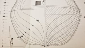
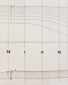
Here you see once more, which frames and which section is part of the Section model
Unfortunately in the drawing set of the kit, there is only one cross section drawing, so we have to calculate by ourself the difference and mark it on the drawing in order to have guidance for the frame elements.
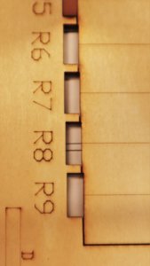
Here you can see the small difference of the width in the jig, with the frame 9 which has the smallest width
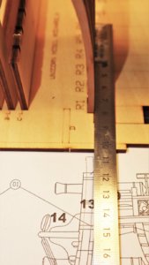
To make it more clear here the side of jig and the cross section drawing of frame 1, which is very close to the midship-section "M" (see Boudriot drawing)
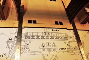
and now we take a look at frame Nr 9
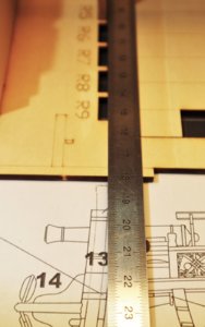
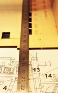
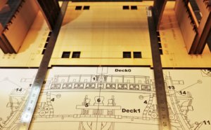
Here a short notice on the sketch copy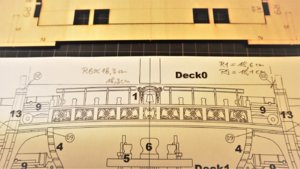
The width of the of R1 is appr. 18,6cm - R9 only 18,1 cm so 5mm less
For the frame Nr.6 with I made yesterday evening we hav appr. 18,3 cm which is marked with pencil lines -> The frame elements of frame Nr.6 have to fit this marks
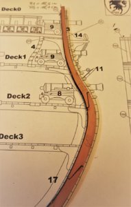
you can see, that the elements are not following any more the cross section sketch
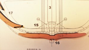
Visible also very much already at the floor timber, when you compare the form with the drawing


To be continued.......
If you look at the section models of other suppliers, like Victory or USS Constitution, I think the frames have over the length of the section everytime the same form.
But in reality, off course the hull form is following the lines of the ship, so every frame has a slightly different form.
Here the excerpts of the Boudriot drawings showing the lines of the Bonhomme Richard


Here you see once more, which frames and which section is part of the Section model

Unfortunately in the drawing set of the kit, there is only one cross section drawing, so we have to calculate by ourself the difference and mark it on the drawing in order to have guidance for the frame elements.
Here you can see the small difference of the width in the jig, with the frame 9 which has the smallest width

To make it more clear here the side of jig and the cross section drawing of frame 1, which is very close to the midship-section "M" (see Boudriot drawing)


and now we take a look at frame Nr 9


Here a short notice on the sketch copy

The width of the of R1 is appr. 18,6cm - R9 only 18,1 cm so 5mm less
For the frame Nr.6 with I made yesterday evening we hav appr. 18,3 cm which is marked with pencil lines -> The frame elements of frame Nr.6 have to fit this marks

you can see, that the elements are not following any more the cross section sketch
Visible also very much already at the floor timber, when you compare the form with the drawing


To be continued.......
Hi Uwe,
So if I understand correctly, is there a slight narrowing of the cross section towards the stern?
So if I understand correctly, is there a slight narrowing of the cross section towards the stern?


