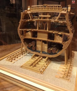
Yes, you summarized it better than meHi Uwe,
So if I understand correctly, is there a slight narrowing of the cross section towards the stern?
-

Win a Free Custom Engraved Brass Coin!!!
As a way to introduce our brass coins to the community, we will raffle off a free coin during the month of August. Follow link ABOVE for instructions for entering.
-

PRE-ORDER SHIPS IN SCALE TODAY!
The beloved Ships in Scale Magazine is back and charting a new course for 2026!
Discover new skills, new techniques, and new inspirations in every issue.
NOTE THAT OUR FIRST ISSUE WILL BE JAN/FEB 2026
You are using an out of date browser. It may not display this or other websites correctly.
You should upgrade or use an alternative browser.
You should upgrade or use an alternative browser.
USS BONHOMME RICHARD - POF - Cross Section in Pear - 1:48 - by Uwe
Interesting.
It would have been so much easier for them to keep all of the frames the same size.
Nice attention to accuracy.
It would have been so much easier for them to keep all of the frames the same size.
Nice attention to accuracy.
Hello Uwe,
fascinating model and excellent start. Ladies files - I always buy them at DM (Drogeriemarkt) they have files from ebelin in different qualities. I like the ones with the smooth and sharp side best, they are flexible and cheap, the only disadvantage is, they are soon worn out in permanent use.
Greetings
Michael
P.S.
Thanks at all for the kind birthday wishes.
I am not 100% sure, because I did not check the quantity of the wooden strips until now -Hi Uwe,
Just a quick question.
Do you get the base/stand as shown in the picture below in the kit?
View attachment 113349
But I do not think, that the material is included, definitely no plate added.
Hallo Michael,Hello Uwe,
fascinating model and excellent start. Ladies files - I always buy them at DM (Drogeriemarkt) they have files from ebelin in different qualities. I like the ones with the smooth and sharp side best, they are flexible and cheap, the only disadvantage is, they are soon worn out in permanent use.
Greetings
Michael
P.S.
Thanks at all for the kind birthday wishes.
many thanks for the additional information and will try once these ladies files
For the need now, for removing the char inside these joints of the elements, the tool has to be stiff, in order not to change angles etc.
But in other situation I am sure, they will work -
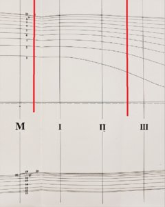
Good progress Uwe.It is a shame that drawings are not provided for each frame in the kit.Indeed all will be slightly different.Looking at your pic of the Monograph framing plan,point M is dead flat,that is not even included in the section modelled,so the section will taper from one end to the other.
Kind Regards
Nigel
Kind Regards
Nigel
Good progress Uwe.It is a shame that drawings are not provided for each frame in the kit.Indeed all will be slightly different.
Yes you are right - this would be usually no problem and would help the modelers very much - especially there is either in the manual or in the drawings an information about different form of the frames - Here Unicorn should add these 9 sketches for preparation of the frames

Looking at your pic of the Monograph framing plan,point M is dead flat,that is not even included in the section modelled,so the section will taper from one end to the other.
Kind Regards
Nigel
You are right once more - here is the line drawing with the approximate markings of the section - Frame 1 is very close to M
The assembly of the frame' pieces of this model is very ... "exotic" and far from realities.
GD
GD
Many thanks for the comment and clarification. I completely agree here - and it makes the work more complicatedThe assembly of the frame' pieces of this model is very ... "exotic" and far from realities.
GD
-> Usually a normal butt joint would be necessary or correct, than definitely it would be necessary to have a drawing for every frame
G'day Uwe, I think that maybe their are so confident with the way the kit has been designed that everything will go together OK,
if you look at the first page in build manual they just show the frames, and I think they are saying this is how to glue them together,
there is no drawing under the frames,
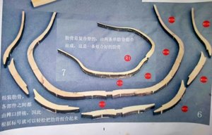
I have been itching to start this model or rather models as I have two of them, so I thought that I would
try the way they show,
I will be starting a build log soon, sorry for hijacking your thread,

Started by gluing up the floors on a piece of white cardboard, this is frame nine,
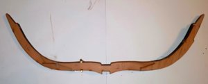
Then added the futtocks etc,
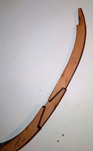
the frames fit together OK,
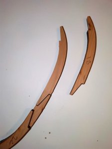
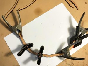
and I clamped the joins as I went,
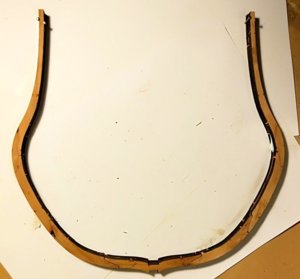
after the glue has dried,
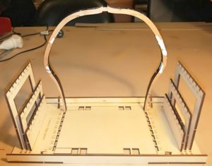
and sitting in the jig, no force was needed it just slipped in nicely, I have now built five frames for a total of approx
three hours, hope you do not mind me posting this on your log,
best regards John,
.
if you look at the first page in build manual they just show the frames, and I think they are saying this is how to glue them together,
there is no drawing under the frames,

I have been itching to start this model or rather models as I have two of them, so I thought that I would
try the way they show,
I will be starting a build log soon, sorry for hijacking your thread,

Started by gluing up the floors on a piece of white cardboard, this is frame nine,

Then added the futtocks etc,

the frames fit together OK,


and I clamped the joins as I went,

after the glue has dried,

and sitting in the jig, no force was needed it just slipped in nicely, I have now built five frames for a total of approx
three hours, hope you do not mind me posting this on your log,
best regards John,
.
Last edited:
For everyone, who want to take a look at John´s building log of his Cherry-version of this section of the Bonhomme Richard, please take a look and use this link.G'day Uwe, I think that maybe their are so confident with the way the kit has been designed that everything will go together OK,
if you look at the first page in build manual they just show the frames, and I think they are saying this is how to glue them together,
there is no drawing under the frames,
View attachment 113713
I have been itching to start this model or rather models as I have two of them, so I thought that I would
try the way they show,
I will be starting a build log soon, sorry for hijacking your thread,
View attachment 113714
Started by gluing up the floors on a piece of white cardboard, this is frame nine,
View attachment 113715
Then added the futtocks etc,
View attachment 113716
the frames fit together OK,
View attachment 113717
View attachment 113718
and I clamped the joins as I went,
View attachment 113719
after the glue has dried,
View attachment 113720
and sitting in the jig, no force was needed it just slipped in nicely, I have now built five frames for a total of approx
three hours, hope you do not mind me posting this on your log,
best regards John,
.
Very interesting and to follow is highly recommended:
USS BONHOMME RICHARD - POF - Cross Section in Cherry - 1:48 - by neptune,
I have had these kits for approx two years now and I have been holding off starting them, once Uwe started his build log it got my juices flowing so here goes, and by the way I will be building two of them at the same time, I will post some pics of the kit contents in awhile, but for now, This...
shipsofscale.com
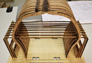
After a very busy business week (inclusive a trip to Prague) and no work on the Bonhomme Richard, I had yesterday the chance to finalize the last two frames and made also the first char sanding of the outer and inner sides of the frames.
In the following you can see the nine double frames temporary installed in the jig.
You will recognize, that the frames 8 and 9 are not extremely sanded, this I want to do later, due to the needs for an accurately beveling.
The small 8 strips between the frames are only temporary and are a content of the kit, these are "only" temporary spacers between the frames.
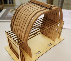
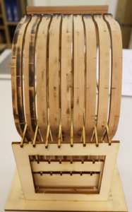
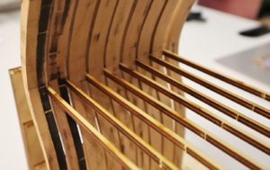
The nine frames outside of the jig (sorry for the blur)
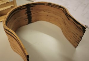
With this perspective you can see good the different form of the frames, the frames are following the lines of the ship

In the following you can see the nine double frames temporary installed in the jig.
You will recognize, that the frames 8 and 9 are not extremely sanded, this I want to do later, due to the needs for an accurately beveling.
The small 8 strips between the frames are only temporary and are a content of the kit, these are "only" temporary spacers between the frames.


The nine frames outside of the jig (sorry for the blur)

With this perspective you can see good the different form of the frames, the frames are following the lines of the ship

Wow she is looking great, I have to take the char off my frames yet, and I have just picked up a couple of hints from your pics,
best regards John,
best regards John,
For everyone, who want to take a look at John´s building log of his Cherry-version of this section of the Bonhomme Richard, please take a look and use this link.
Very interesting and to follow is highly recommended:
USS BONHOMME RICHARD - POF - Cross Section in Cherry - 1:48 - by neptune,
I have had these kits for approx two years now and I have been holding off starting them, once Uwe started his build log it got my juices flowing so here goes, and by the way I will be building two of them at the same time, I will post some pics of the kit contents in awhile, but for now, This...shipsofscale.com
Thanks again for your kind comments, it is going to be interesting to compare how we both work on these kits, also now that i have my log running you can if you want delete the pics I posted up above on your log so it is not so cluttered and thank you for adding a link to my log,
best regards john,
John explained in his building log, that
I decided yesterday, that I want to try first of all the original way, with the steps at each double frame - indeed, this detail will be not visible any more, when the frames are sitting on top of the keel, but you can see the eight small spacers on top of the deadwood between the double frames.
So I started to prepare the joints, in order to get the frames sitting flat on the keel deadwood and also rectangular. Here the status of four prepared frames
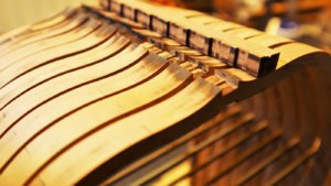
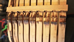
to be continued .......
View attachment 114129
I was not too happy with the keel made up from all the pieces, so i had a nice piece of Pear and I cut new
keels out of that and to save a little bit of messing around I am just going to leave it flat on the top,
View attachment 114130
Because I was leaving the keel flat on the top I had to file away the step inside the frame so it would
sit nicely on the keel,
View attachment 114131
the frame just sitting on the keel,
I decided yesterday, that I want to try first of all the original way, with the steps at each double frame - indeed, this detail will be not visible any more, when the frames are sitting on top of the keel, but you can see the eight small spacers on top of the deadwood between the double frames.
So I started to prepare the joints, in order to get the frames sitting flat on the keel deadwood and also rectangular. Here the status of four prepared frames


to be continued .......
BTW: It is really very positive, either for me and John, but also for the members following our two building logs, to see the different ways and partly construction methods to solve the upcoming tasks of such a kit model.
So every model is somehow different -> very interesting to follow in my opinion
So every model is somehow different -> very interesting to follow in my opinion
- Joined
- Aug 16, 2019
- Messages
- 870
- Points
- 343

What a nice build
I just love that kit unfortunately the only thing I can’t do is look in admiration about it
I just love that kit unfortunately the only thing I can’t do is look in admiration about it
Yesterday I finalized the preparation of every single step on the deadwood of the keel, so that the frames fit very good on top of the keel
The floor timbers of the the frames are now all on the same height compared to the keel
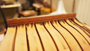
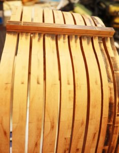
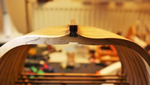
The next working step was to prepare the notches on every frame, so that the false keel will fit.
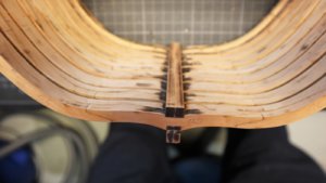
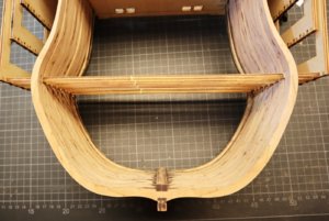
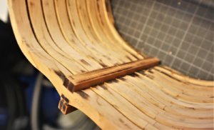
In moment is dry fitted, before I permanently fix it with glue, I want to remove the char on the frames next to keel and false keel.
Later on, it would be more complicated
To be continued .....
The floor timbers of the the frames are now all on the same height compared to the keel


The next working step was to prepare the notches on every frame, so that the false keel will fit.


In moment is dry fitted, before I permanently fix it with glue, I want to remove the char on the frames next to keel and false keel.
Later on, it would be more complicated
To be continued .....
- Joined
- Sep 28, 2018
- Messages
- 250
- Points
- 373

Ciao, ottimo lavoro, una cosa non ho capito, ma i pezzi li tagli tu al laser oppure è un kit? Scusa la mia ignoranza 
google translation:
Hi, great job, one thing I didn't understand, but you cut the pieces to the laser or is it a kit? Excuse my ignorance
google translation:
Hi, great job, one thing I didn't understand, but you cut the pieces to the laser or is it a kit? Excuse my ignorance
Last edited by a moderator:


