Very good and precision joinery work,Uwe!
-

Win a Free Custom Engraved Brass Coin!!!
As a way to introduce our brass coins to the community, we will raffle off a free coin during the month of August. Follow link ABOVE for instructions for entering.
-

PRE-ORDER SHIPS IN SCALE TODAY!
The beloved Ships in Scale Magazine is back and charting a new course for 2026!
Discover new skills, new techniques, and new inspirations in every issue.
NOTE THAT OUR FIRST ISSUE WILL BE JAN/FEB 2026
You are using an out of date browser. It may not display this or other websites correctly.
You should upgrade or use an alternative browser.
You should upgrade or use an alternative browser.
USS BONHOMME RICHARD - POF - Cross Section in Pear - 1:48 - by Uwe
- Joined
- Dec 1, 2016
- Messages
- 6,390
- Points
- 728

I tried several ways to remove char from joinery. I found any sanding tends to round out the flat surface, it seems the edges get sanded faster than the rest of the surface. I use a single edge razor blade and scrape the surface that works better than sanding. I realize not everyone had an airbrush but I have a sand blasting nozzle on my airbrush and a quick pass over the parts and BAM! the char is totally gone. The sanding grit hits the surface all at once so there is no rounding off the edges.
This sounds interesting - can you maybe show us a photo of this "airbrush with sand blasting nozzle" ?I tried several ways to remove char from joinery. I found any sanding tends to round out the flat surface, it seems the edges get sanded faster than the rest of the surface. I use a single edge razor blade and scrape the surface that works better than sanding. I realize not everyone had an airbrush but I have a sand blasting nozzle on my airbrush and a quick pass over the parts and BAM! the char is totally gone. The sanding grit hits the surface all at once so there is no rounding off the edges.
Hallo my friend,Ciao, ottimo lavoro, una cosa non ho capito, ma i pezzi li tagli tu al laser oppure è un kit? Scusa la mia ignoranza
google translation:
Hi, great job, one thing I didn't understand, but you cut the pieces to the laser or is it a kit? Excuse my ignorance
no problem -
Yes! It is a kit from a chinese manufacturer - take a look at this topic, where I introduce the kit:
Kit Review - USS BONHOMME RICHARD - Full rib Cross Section (Pear version) - Scale 1:48 - Unicorn models
Based on the extreme good quality I could see in the building log of @OlegM with his USS Bonhomme Richard from the same manufacturer https://shipsofscale.com/sosforums/threads/uss-bonhomme-richard-1779-1-48.3383/#post-66384 I was convinced, that this section model will be also a very good...
shipsofscale.com
That sounds interesting Dave, but even then the frames still have to be hand sanded to get an even surface for laying the planks on, and I find that by sanding the char off this way the char gives a guide to what area's to sand,I tried several ways to remove char from joinery. I found any sanding tends to round out the flat surface, it seems the edges get sanded faster than the rest of the surface. I use a single edge razor blade and scrape the surface that works better than sanding. I realize not everyone had an airbrush but I have a sand blasting nozzle on my airbrush and a quick pass over the parts and BAM! the char is totally gone. The sanding grit hits the surface all at once so there is no rounding off the edges.
Best regards John,
You are right with the frames, and when you are sanding the hulls form. I think, that this sandblasting would be very useful for the joints preparation of the timbers and futtocks of each frame......and other areas, where it is not easy to reachThat sounds interesting Dave, but even then the frames still have to be hand sanded to get an even surface for laying the planks on, and I find that by sanding the char off this way the char gives a guide to what area's to sand,
Best regards John,
How was your Pear wood to sand, my Cherry was really hard, I started off with 120 grit sandpaper but ended up with 40 grit for the basic removal of the char and to get the frames level across their width and finished with the 120 grit, I am pleased with the way they have finished, just got to do the insides now, ,
Best regards john,
Best regards john,
Until now I made the preliminary sanding of the frames with my spindle sander - so the work was done by the machineHow was your Pear wood to sand, my Cherry was really hard, I started off with 120 grit sandpaper but ended up with 40 grit for the basic removal of the char and to get the frames level across their width and finished with the 120 grit, I am pleased with the way they have finished, just got to do the insides now, ,
Best regards john,
JET JBOS-5 Oscillating Spindle Sander - my new toy
Some days ago I received my new "tool-toy". It is the Jet JBOS-5 Spindle sander. In the following I want to show you this interesting tool, today the important figures and the delivered content and in the following some experience using this tool during my built of the La Salamandre It is a...
shipsofscale.com
But read also the following post
Yesterday I made only some smaller progress, with cleaning and sanding the face sides of the frames - I had to remove the pencil marks and the rests of the glue and paper, which were stick during gluing. Here I used 240 grid and later 320 grid (by hand) to get everything removed.
In addition I made a trial and wanted to show some bolts holding the timbers and futtocks together - this I made on one side of the frame number two which is covered by frame 1 and 3 - so that I could check if they will be visible later one
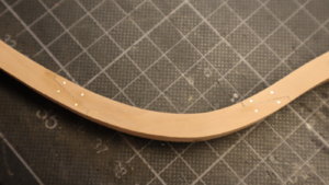
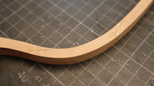
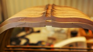
Now the check if they are visible
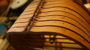
here an enlargement of the same photo (incl. brightening to see it better) - ad the ends of the red arrows you can slightly see the "bolts"
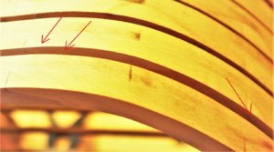
Hardly to see, so I decided not to make them on the frames 2 to 8. I will show them later on on the frames 1 and 9 - at the visible front sides of the section
I have a question to you all and want some advice and information - I was thinking about how would be the real bolting of such a joint.
Due to the fact, that such a double frame has two layers, where the joints of the other layer is displaced / staggered there should be additional heads of "bolts" visible, or? Like a marked it red (dotts)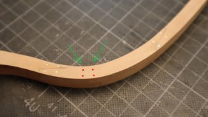
here I borrowed one photo from John, where the displacement of the two half of the frame can be seen very good (John, I hope this is ok for you?)

In addition I made a trial and wanted to show some bolts holding the timbers and futtocks together - this I made on one side of the frame number two which is covered by frame 1 and 3 - so that I could check if they will be visible later one


Now the check if they are visible

here an enlargement of the same photo (incl. brightening to see it better) - ad the ends of the red arrows you can slightly see the "bolts"

Hardly to see, so I decided not to make them on the frames 2 to 8. I will show them later on on the frames 1 and 9 - at the visible front sides of the section
I have a question to you all and want some advice and information - I was thinking about how would be the real bolting of such a joint.
Due to the fact, that such a double frame has two layers, where the joints of the other layer is displaced / staggered there should be additional heads of "bolts" visible, or? Like a marked it red (dotts)

here I borrowed one photo from John, where the displacement of the two half of the frame can be seen very good (John, I hope this is ok for you?)

USS BONHOMME RICHARD - POF - Cross Section in Cherry - 1:48 - by neptune,
I have had these kits for approx two years now and I have been holding off starting them, once Uwe started his build log it got my juices flowing so here goes, and by the way I will be building two of them at the same time, I will post some pics of the kit contents in awhile, but for now, This...
shipsofscale.com
Uwe
As you know the frames are not truly typical of sistered frame construction due to the scarph.Normally with sistered frames there are three bolts spaced evenly in each overlap centrally piercing both frames.Some variation on this could be possible.Scarphs are bolted through the scarph.
I think you just have to go with what is aesthetically pleasing as the kit design is not true to reality.
I did choose not to portray bolts on Saint Philippe after much consideration,I felt their size at 1/36 would draw the eye and detract from the joinery even with such a small gap between frames.
It is all down to personal preference,in your model if I was going to show bolting,I would probably have gone for just three bolts equally in each overlap.You could show the bolts cross bolting the scarphs but visually you would have lines of bolts one side of the joint on the outside of the hull which would possibly be unpleasing to the eye.
Kind Regards
Nigel
Many thanks for the information and your opinion - highly appreciated.Uwe
As you know the frames are not truly typical of sistered frame construction due to the scarph.Normally with sistered frames there are three bolts spaced evenly in each overlap centrally piercing both frames.Some variation on this could be possible.Scarphs are bolted through the scarph.
I think you just have to go with what is aesthetically pleasing as the kit design is not true to reality.
I did choose not to portray bolts on Saint Philippe after much consideration,I felt their size at 1/36 would draw the eye and detract from the joinery even with such a small gap between frames.
It is all down to personal preference,in your model if I was going to show bolting,I would probably have gone for just three bolts equally in each overlap.You could show the bolts cross bolting the scarphs but visually you would have lines of bolts one side of the joint on the outside of the hull which would possibly be unpleasing to the eye.
Kind Regards
Nigel
These kind of joints were not used in the french construction, you are right, but were partly used at english ships (I think).......It is hard decision, but I am able to shift it a little bit until a far later stage of the construction, due to the fact, that I will only show them at the outer frames 1 and 9 or at the outside of the hull (either way where I will make them.
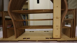
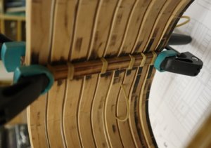
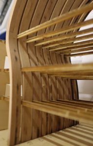
Yesterday I installed the frames and glued them together with the spacers. Keel and keelson are only fixed with some rubber bands, I want to remove them partly so I can sand the frames without damaging these parts.
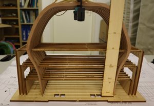
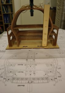
This board shows the levels of the gunports, for later markings with pencil
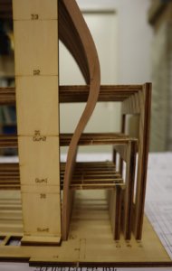
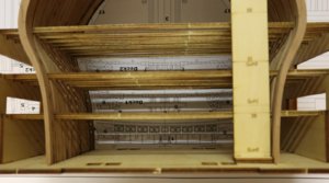
At the back you can see the drawing of the cross section
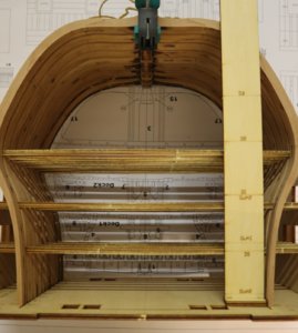
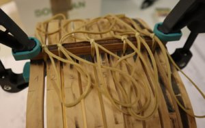
The rubber bands the press the keel and keelson towards the frames
the construction for the spacers, so they are all in the same height - nice idea
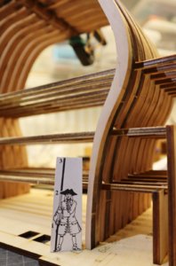
and I found my old friend - the shipyard supervisor - he started already to check the measurements
Many Thanks for your interest ..... to be continued


This board shows the levels of the gunports, for later markings with pencil


At the back you can see the drawing of the cross section


The rubber bands the press the keel and keelson towards the frames


the construction for the spacers, so they are all in the same height - nice idea

and I found my old friend - the shipyard supervisor - he started already to check the measurements

Many Thanks for your interest ..... to be continued
A
Asat
Guest
Dave is this the sand blaster? It’s $27.99 at Harbor Freight
Dave may answer better, as I don't have experience with sandblasters. But to me, this looks more like a gravity feed airbrush with a large paint container. For sand, this will be too small (IMHO).Dave is this the sand blaster? It’s $27.99 at Harbor Freight
A
Asat
Guest
No, it’s listed as a air eraser/etching kit and the description says “it operates like a small sand blaster but more accurate”. It’s item # 69277 on the harbor freight website. The reviews are good and people ar3 using baking soda, and aluminum oxide 220-240 grit media in it. It needs 65psi though so a small airbrush compressor probably won’t do it.....
I have to check in the drawings! Either kit and / or Boudriot ....She is coming on nicely Uwe, it is surprising how much work there is in these sections.
I was wondering if you had any idea what size the wood is that support the decks I will attach a pic of what I mean, I think they might be 7x3mm but not sure,
View attachment 114772
best regards John,
and you are correct - It is still a lot of hours working on this model
Hi Uwe, I have just checked the kit drawing and the wood supplied in my kits and there is only enough 7x3mm to do the wales but they have 6x2mm strips running all the way up the inside of the frames and they are just sitting the beams on them, see pic 56 in the instructions, I should have spotted this earlier,
Best regards John,
Best regards John,
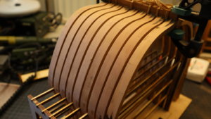
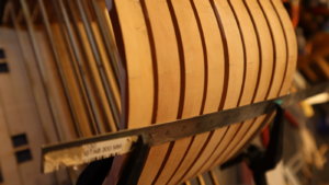
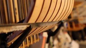
Yesterday I sanded the outside area of the frames, this part above the spacers - at the end I did it by hand without power tool. Takes much more time, but I think that the result is better
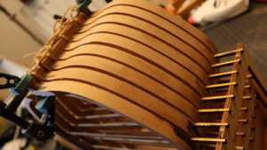
afterwards I removed the elements of the jig which kept the spacersticks in the correct height - so do not glue this part of the jig
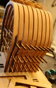
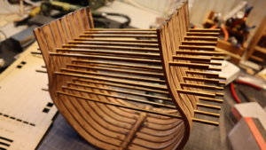


afterwards I removed the elements of the jig which kept the spacersticks in the correct height - so do not glue this part of the jig


