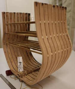
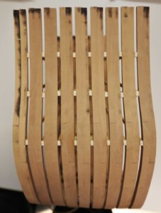
USS BONHOMME RICHARD - POF - Cross Section in Pear - 1:48 - by Uwe

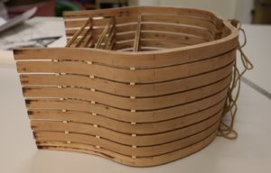
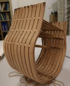
In Johns alias @neptune topic somebody asked about the possibility of adding a second section in order to prolong the section from 9 to 18 frames.

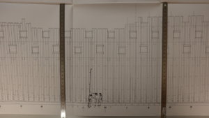
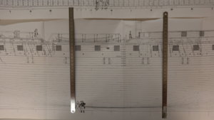
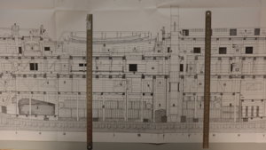
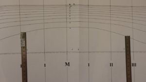
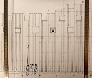
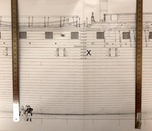
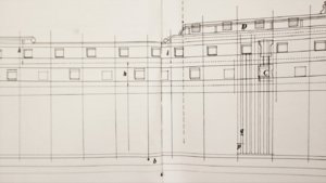
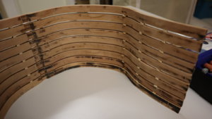
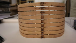
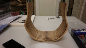
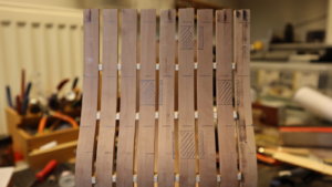
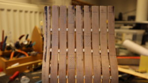
So I took the Boudriot drawings of the HMS Bonhomme Richard and checked it roughly - The border lines would be the metal rulers

IMG_4211.JPG

you can see, that with the left gunport you could get some problems to solve this detail, maybe with making one frame less
IMG_4212.JPG

IMG_4213.JPG

Also here we have some slight problem, but I think the lines (on the modelframes) can be adjusted
IMG_4215.JPG
 
Thank you Uwek for checking it out . I think somebody is producing a set of ship boats especially for the Bonhomme Richard. How great would it look to have those sitting on deck and halved at the right point
Would it really be so such a tragic if the lines would not be 100 % true ??
Aesthetically it would be even better to not attach the two sections but keep some space between them when mounting on a display board
I do not know, of a special produced set of the three boats, But they were standard boats, so I guess you can use similar types, like longboat, pinnace and cutter.
If the lines are not 99 or 100% correct, this every modeler should decide by him/her-self, and to be honest, it will be hard to see. And if necessary it would be in my opinion only the last two frames which should be built new to get the absolute more correct form.
In my opinion it is a good idea - and maybe......
 
Hello Uwe, have you any idea why on the drawings it shows a port on the frame plan but not on the planked plan,

View attachment 114924


View attachment 114925
There must be a reason, was just wondering,

best regards John,
Hallo John,
I know why there are differences in the drawing, but I will need some time to prepare the detailed answer - I guess tomorrow and can show it.
 
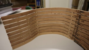
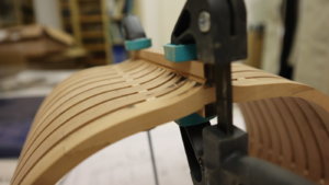
Today I was able to sand the outside part of the section - I try to make it as accurate as possible and still without power tools, so it takes some time - sorry for the boring progress reports
What I can state is, that the chosen timber are great :cool:

IMG_42341.jpg

IMG_42351.jpg

IMG_42361.jpg

IMG_42381.jpg
 
I do not know, of a special produced set of the three boats, But they were standard boats, so I guess you can use similar types, like longboat, pinnace and cutter.
If the lines are not 99 or 100% correct, this every modeler should decide by him/her-self, and to be honest, it will be hard to see. And if necessary it would be in my opinion only the last two frames which should be built new to get the absolute more correct form.
In my opinion it is a good idea - and maybe......

G'day Uwe, here is the link to a set of three for the BH Richard, I do not know how accurate they are,

https://www.ebay.com.au/itm/USS-Bon...a=1&pg=2047675&_trksid=p2047675.c100010.m2109


.
 
I do not know, of a special produced set of the three boats, But they were standard boats, so I guess you can use similar types, like longboat, pinnace and cutter.
If the lines are not 99 or 100% correct, this every modeler should decide by him/her-self, and to be honest, it will be hard to see. And if necessary it would be in my opinion only the last two frames which should be built new to get the absolute more correct form.
In my opinion it is a good idea - and maybe......

Thanks Uwe
Wasn't such a barmy idea of mine after all ROTF

Kind Regards

Nigel
 
@neptune

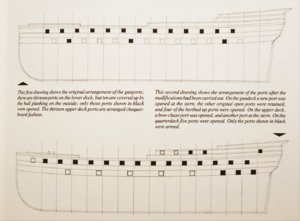
The ports are planked because the framework from the Duc de Duras was preparated to switch into a warship if it nescesary. The Bonhomme Richard received any modifies for her duty in the continental navy and some ports were closed, others were opened.

Thank you Oliver for the explanation, it makes sense now,

best regards John.
 
Hello Uwe, have you any idea why on the drawings it shows a port on the frame plan but not on the planked plan,

View attachment 114924


View attachment 114925
There must be a reason, was just wondering,

best regards John,

@neptune

The ports are planked because the framework from the Duc de Duras was preparated to switch into a warship if it nescesary. The Bonhomme Richard received any modifies for her duty in the continental navy and some ports were closed, others were opened.

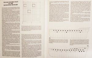
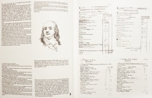
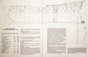
In addition to Olivers answer I want to use the time to show it more in detail, and that you have something to read. These are information, which you can get in detail, only if you have such a detailed monograph in hand, so especially builder of the complete model but also for builder of such a section model, should think about getting one copy of the Jean Boudriot planset into your hands.

The following excerpts are from this planset


IMG_42211.jpg

IMG_42201.jpg

IMG_42221.jpg

IMG_42161.jpg

IMG_42191.jpg

Several information are important, also for the historical correct execution of the section.
- The original gunports were partly closed, means a new planking was covering the gunport openings between the frames.
- The existing gunports were widened (for 18pdr guns) and slightly shifted
- Related to the section: If we read correctly, only two of the four gunports shown in the section were armed. (photo 2 shows this very good)
 
I realized, that I did not show the history of the ship USS Bonhomme Richard. With the knowledge of her career, it will be also more clear, why there was this reconstruction and modification of the ship.

from wikipedia:

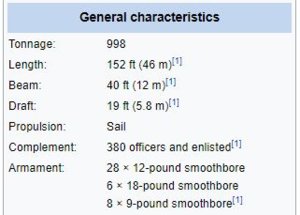
Bonhomme Richard, formerly Duc de Duras, was a warship in the Continental Navy. She was originally an East Indiaman, a merchant ship built in France for the French East India Company in 1765, for service between France and the Orient. She was placed at the disposal of John Paul Jones on 4 February 1779, by King Louis XVI of France as a result of a loan to the United States by French shipping magnate Jacques-Donatien Le Ray.
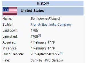
aa.JPG ab.JPG

Origin
Bonhomme Richard was originally an East Indiaman named Duc de Duras, a merchant ship built at Lorient according to the plan drawn up by the King's Master Shipwright Antoine Groignard for the French East India Company in 1765. Her design allowed her to be quickly transformed into a man-of-war in case of necessity to support the navy. She made two voyages to China, the first in 1766 and the second in 1769. At her return the French East India Company had been dissolved, and all its installations and ships transferred to the French Navy. As a naval ship she made a voyage to Isle de France (Mauritius) before being sold to private shipowners in 1771. She sailed in private service until she was purchased by King Louis XVI of France in early 1779 and placed under the command of John Paul Jones on 4 February. The size and armament of Duc de Duras made her roughly equivalent to half of a 64-gun ship of the line.

Jones renamed her Bon Homme Richard (usually rendered in more correct French as Bonhomme Richard) in honor of Benjamin Franklin, the American Commissioner at Paris whose Poor Richard's Almanac was published in France under the title Les Maximes du Bonhomme Richard.

First patrols
On 19 June 1779, Bonhomme Richard sailed from Lorient accompanied by USS Alliance, Pallas, Vengeance, and Cerf with troop transports and merchant vessels under convoy to Bordeaux and to cruise against the British in the Bay of Biscay. Forced to return to port for repair, the squadron sailed again 14 August 1779. It went northwest around the west coast of the British Isles into the North Sea and then down the east coast. The squadron took 16 merchant vessels as prizes.

Battle of Flamborough Head
Further information: Battle of Flamborough Head

Bonhomme Richard on fire

On 23 September 1779, the squadron encountered the Baltic Fleet of 41 sail under convoy of HMS Serapis and HM hired armed ship Countess of Scarborough near Flamborough Head. Bonhomme Richard and Serapis entered a bitter engagement at about 6:00 p.m. The battle continued for the next four hours, costing the lives of nearly half of the American and British crews. British victory seemed inevitable, as the more heavily armed Serapis used its firepower to rake Bonhomme Richard with devastating effect. The commander of Serapis finally called on Jones to surrender. He replied, "Sir, I have not yet begun to fight!" Jones eventually managed to lash the ships together, nullifying his opponent's greater maneuverability and allowing him to take advantage of the larger size and considerably more numerous crew of Bonhomme Richard. An attempt by the Americans to board Serapis was repulsed, as was an attempt by the British to board Bonhomme Richard. Finally, after another of Jones's ships joined the fight, the British captain was forced to surrender at about 10:30 p.m. Bonhomme Richard – shattered, on fire, leaking badly – defied all efforts to save her and sank about 36 hours later at 11:00 a.m. on 25 September 1779. Jones sailed the captured Serapis to the Dutch United Provinces for repairs.

Though Bonhomme Richard sank after the battle, the battle's outcome was one of the factors that convinced the French crown to back the colonies in their fight to become independent of British authority.

Search for the wreck
Bonhomme Richard's final resting location was the subject of much speculation. A number of unsuccessful efforts had been conducted to locate the wreck. The location was presumed to be in approximately 180 feet (55 m) of water off Flamborough Head, Yorkshire, a headland near where her final battle took place. The quantity of other wrecks in the area and a century of fishing trawler operations had complicated all searches.

One season's attempts to locate and retrieve the ship, or some artifacts from her, using USNS Grasp were filmed for the Discovery Channel's Mighty Ships series in 2011. The U.S. Navy's mission was unsuccessful. In 2012, an expedition with the Ocean Technology Foundation and the French Navy located a wreck of interest (called "Target 131") in 70 meters of water. The wreck is mostly buried, but some artifacts are visible on the seabed surface, including an anchor that would fit the dimensions and style of the kedge anchor on the Bonhomme Richard. In 2014, the French Navy and Ocean Technology Foundation mounted an expedition to have the French Navy dive Target 131. Artifacts discovered by the divers included a deadeye block (part of a sailing ship's rigging), large sections of half-buried planking, and what appeared to be an iron spar hoop, with a few pieces of decomposing wood still encircled in it. No evidence of modern objects has been found on the site. The Global Foundation for Ocean Exploration (GFOE) has since continued the work of the Ocean Technology Foundation, leading an expedition with the French and U.S. Navies in 2016, again aboard the USNS Grasp. More remote sensing was conducted, and researchers discovered additional objects within the wreck site that were deemed worthy of further investigation. A 2019 expedition involving GFOE, the French Navy, and the U.S. Navy was planned, but was postponed indefinitely due to a disagreement among France and the U.S. about the ultimate ownership of the Bonhomme Richard. The goal of this mission was to prove or disprove Target 131 as being the Bonhomme Richard.

In 2018 remains, possibly those of the Bonhomme Richard, were found in shallow water very close to the coast of Filey, North Yorkshire, England, by the Land and Sea search team Merlin Burrows. However, the location of this wreck does not corroborate with multiple eyewitness accounts from observers on land, who noted that on the morning of September 25, 1779, the Bonhomme Richard disappeared out of sight over the horizon.


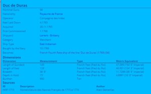
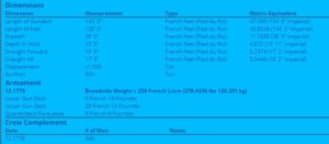
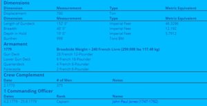
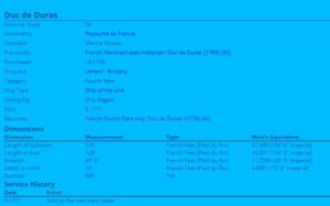
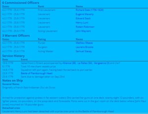
And on ThreeDecks we can find these information:

DUC de DURAS
cc.JPG

dd.JPG

ac.JPG
ad.JPG

Bon Homme Richard / Bonhomme Richard
bb.JPG
bc.JPG
bd.JPG


Many Thanks for all your friendly comments and likes received before - highly appreciated

Yesterday some small progress and sanding and fairing the frames - I forgot how much work it is

But it is only one side inside missing. Some smaller spots of and areas are still with char, but they will be covered by planks, so no need to remove them completely, important is the form of the frames.

IMG_4240.JPG

this area is the work for this coming evening
IMG_4241.JPG

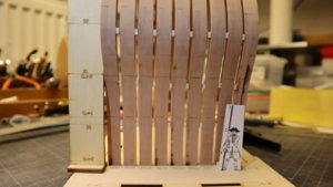
you can see, that I made also two rows of spacers parallel to the keel - with this the frame-package is stabile enough for sanding (without keel and keelson)
IMG_4242.JPG

IMG_4243.JPG
 
She is looking great Uwe, I didn't realize about gluing the spacers into the frames, I just thought they were temporary spacers, was having a Senior moment :mad::mad::mad:, they turned out good for you,

best regards John,
 
She is looking great Uwe, I didn't realize about gluing the spacers into the frames, I just thought they were temporary spacers, was having a Senior moment :mad::mad::mad:, they turned out good for you,

best regards John,
I realized this also very late, looking three (or more) times through the photos of the manual. It was one of my rare positive moments ;)
 
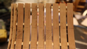
Yesterday I finalized the sanding, so afterwards I was able to mark the gunports

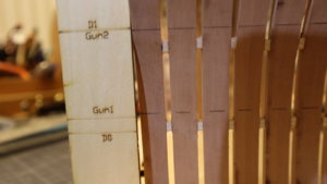
For this there is clever small measurement jig included in the kit - you can see it on the left side of the photo, marked with "Gun0", "Gun1" and "Gun2".
The other marks with "D0", "D1" etc. are the levels for the "decks" - which will be necessary later on
IMG_4244.JPG

With this I was able to make the markings for the next part
IMG_4245.JPG

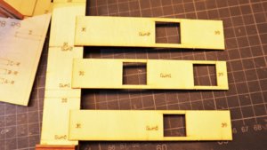
These are the patterns for the gunport - openings
IMG_4246.JPG

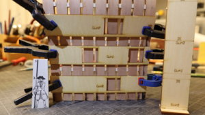
and temporary fixed it to the section frames
IMG_4247.JPG

for the other side the patterns has to be turned
IMG_4248.JPG

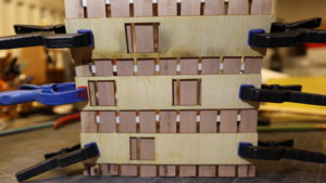
And the marked gunports on both sides
IMG_4249.JPG

IMG_4250.JPG

Many Thanks for your interest - to be continued .......
 
Today I had not so much free-time, so not much done, but I want to show it shortly.

I realized, that one end of a double frame would be loose, after I would cut out of the highest gunport. So I had to glue additional spacers at the top end of the frames
IMG_4252.JPG

Afterwards I made the rabbet more deep and adjusted it according the form of the frames, so that the installation of the garboard strake will be easier
IMG_4253.JPG

IMG_4254.JPG

IMG_4255.JPG

Afterwards I glued the keelson against the frames, so that I can start with the inside planking of the hold. The keel is only temporary fixed, and I will remove it as soon the glue for the keelson is dry. I am afraid, that the edges of the keel could be damaged during the following modeling works. Keel can be easily installed also later.
IMG_4256.JPG

Many thanks for the interest .... to be continued ......
 
Back
Top