Love the finish Uwe, oil?
-

Win a Free Custom Engraved Brass Coin!!!
As a way to introduce our brass coins to the community, we will raffle off a free coin during the month of August. Follow link ABOVE for instructions for entering.
-

PRE-ORDER SHIPS IN SCALE TODAY!
The beloved Ships in Scale Magazine is back and charting a new course for 2026!
Discover new skills, new techniques, and new inspirations in every issue.
NOTE THAT OUR FIRST ISSUE WILL BE JAN/FEB 2026
You are using an out of date browser. It may not display this or other websites correctly.
You should upgrade or use an alternative browser.
You should upgrade or use an alternative browser.
USS BONHOMME RICHARD - POF - Cross Section in Pear - 1:48 - by Uwe
Beautiful work Uwe, nice to see your updates from the shop!
Yes, I think I will use some oil for final finish - I have good experience with swedish palm oil, or some other oil..... will seeLove the finish Uwe, oil?
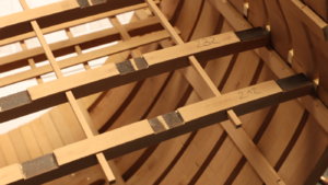
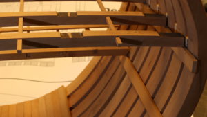
I started to prepare the deck beams and the construction of the carlings etc. it is more to understand the complete construction and the different connecting points with the frames, inner planking, riders etc.
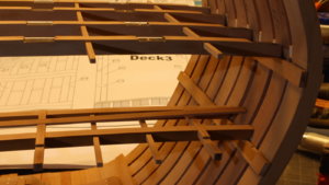
Here the construction for the so called "deck 3" - nothing is glued together - everything fits well together after some smaller adjustments
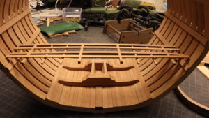
Here you can see the type of construction
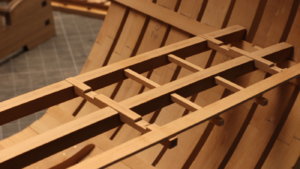
I also started with the beams on the so called "deck 2"
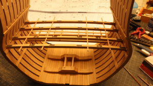
and some details
Many Thanks for your interest ..... to be continued .....
Here the construction for the so called "deck 3" - nothing is glued together - everything fits well together after some smaller adjustments

Here you can see the type of construction

I also started with the beams on the so called "deck 2"

and some details


Many Thanks for your interest ..... to be continued .....
Once more I was able to be some hours in the workshop - and the hours are running and melting like snow in the sun.
I fixed the beams of deck 2 with additional plank(s) with notches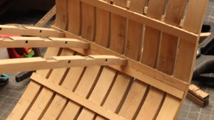
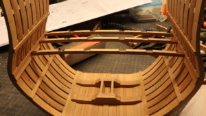
And than it started that I made a big mistake - and the problem is the fact, that with this construction of the section you have to think twice or three times what was first - The chicken or the egg?????
In order to fix the main raider, the inner planking of deck 2 has to be finished, so I did it - glued - starting to dry - it was looking fine, but I had to remove them (with some slight damage)
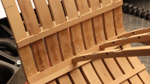
because it is necessary to cut out the gunport of this deck - and than off course also the connecting areas between the inner planking an the gunport frames.
So I put the planks and the main raider on side and started to cut the gunports of this deck
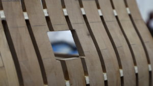
Here a big help are the drawings from Boudriot, but unfortunately they are also not telling us everything
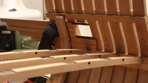
The first gunports are cut out in the section - a first "destroying" of the hull
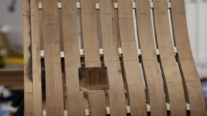
and also started the framing, which is very necessary to make it correct and accurate, due to the fact, that these gun ports have lids
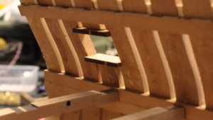
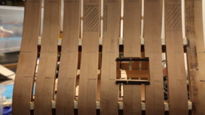
Here for a better understanding of the complete story a photo showing the raider in place and the inner planking, the sides of the gunport-frame are still missing
Many Thanks for your interest ..... to be continued .....
I fixed the beams of deck 2 with additional plank(s) with notches


And than it started that I made a big mistake - and the problem is the fact, that with this construction of the section you have to think twice or three times what was first - The chicken or the egg?????
In order to fix the main raider, the inner planking of deck 2 has to be finished, so I did it - glued - starting to dry - it was looking fine, but I had to remove them (with some slight damage)

because it is necessary to cut out the gunport of this deck - and than off course also the connecting areas between the inner planking an the gunport frames.
So I put the planks and the main raider on side and started to cut the gunports of this deck

Here a big help are the drawings from Boudriot, but unfortunately they are also not telling us everything
The first gunports are cut out in the section - a first "destroying" of the hull

and also started the framing, which is very necessary to make it correct and accurate, due to the fact, that these gun ports have lids


Here for a better understanding of the complete story a photo showing the raider in place and the inner planking, the sides of the gunport-frame are still missing

Many Thanks for your interest ..... to be continued .....
Today some more work on the lower gunport(s) - but first of all I had to make some research, how the sills were installed at the Bonhomme Richard.
Due to the fact, that she was originally a french vessel, I can not fully follow books like "The Construction and fitting ..... " by Peter Goodwin.
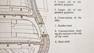
First of all what is shown in the drawings of the Bonhomme Richard by Boudriot, here only the cross section is telling us something
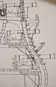
....but not everything
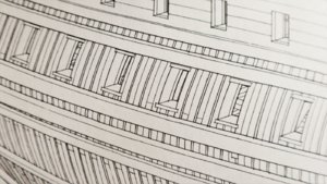
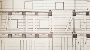
so taking a look at Boudriots 74 gun ship - here it is much more clear shown - the lower sill is different to english ships, and has a bigger depth and ends flash with the inner planking
Here we can see the sills of the 74-gun ship
And the view from the inside - the lower sill is visible, the upper sill is covered by the inner planking -> Now I now, how to build the gunports - I have to state, that here the kit manual and the kit drawings are historically and technically wrong and I will adjust this detail like Boudriot is showing it.
The sills are installed
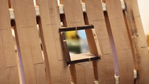
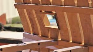
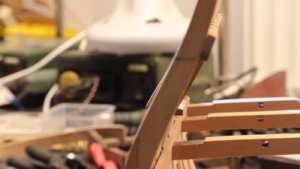
and so it will look like
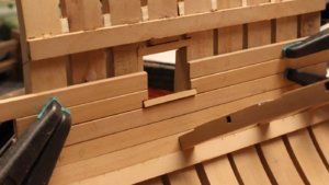
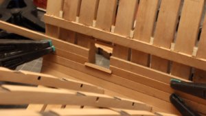
Many Thanks for the interest ..... to be continued ......
Due to the fact, that she was originally a french vessel, I can not fully follow books like "The Construction and fitting ..... " by Peter Goodwin.
First of all what is shown in the drawings of the Bonhomme Richard by Boudriot, here only the cross section is telling us something

....but not everything
so taking a look at Boudriots 74 gun ship - here it is much more clear shown - the lower sill is different to english ships, and has a bigger depth and ends flash with the inner planking

Here we can see the sills of the 74-gun ship

And the view from the inside - the lower sill is visible, the upper sill is covered by the inner planking -> Now I now, how to build the gunports - I have to state, that here the kit manual and the kit drawings are historically and technically wrong and I will adjust this detail like Boudriot is showing it.

The sills are installed


and so it will look like


Many Thanks for the interest ..... to be continued ......
Such a clean work. Outstanding joinery and pear... Just lovely.Today some more work on the lower gunport(s) - but first of all I had to make some research, how the sills were installed at the Bonhomme Richard.
Due to the fact, that she was originally a french vessel, I can not fully follow books like "The Construction and fitting ..... " by Peter Goodwin.
First of all what is shown in the drawings of the Bonhomme Richard by Boudriot, here only the cross section is telling us something
View attachment 127321
....but not everything
so taking a look at Boudriots 74 gun ship - here it is much more clear shown - the lower sill is different to english ships, and has a bigger depth and ends flash with the inner planking
View attachment 127322
Here we can see the sills of the 74-gun ship
View attachment 127323
And the view from the inside - the lower sill is visible, the upper sill is covered by the inner planking -> Now I now, how to build the gunports - I have to state, that here the kit manual and the kit drawings are historically and technically wrong and I will adjust this detail like Boudriot is showing it.
View attachment 127324
The sills are installed
View attachment 127325
View attachment 127326
View attachment 127327
and so it will look like
View attachment 127328
View attachment 127329
Many Thanks for the interest ..... to be continued ......
Excellent work Uwe.
Ahh the chicken and the egg,the hard part around rider timbers that pierce the gundeck and extend over the spirketing and ceiling timbers Many of these on Saint Philippe.Easy to do in scale 1/1 not so easy when you can't climb inside the model
We both know that there are historical inaccuracies in this area.My question looking at the pictures is how do you propose to represent the waterway?In reality,the plank on top of the beams wasn't there.The waterway was notched on the underside to sit and clamp these beams.
I understand that compromises need to be made,otherwise more often than not it is best to start from scratch.The hard decisions we have to make are how far to take things?
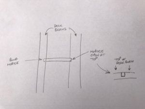
If you are to leave areas of the decks unplanked.I would be tempted to open the tops of the mortices out to the top face on one side of the deck beams.This is an easy modification but as I am sure you are aware only one end of the carling goes into a blind mortice.The other mortice is open on the topside to allow them to be fitted in the shipyard.
Kind Regards
Nigel
Ahh the chicken and the egg,the hard part around rider timbers that pierce the gundeck and extend over the spirketing and ceiling timbers
 Many of these on Saint Philippe.Easy to do in scale 1/1 not so easy when you can't climb inside the model
We both know that there are historical inaccuracies in this area.My question looking at the pictures is how do you propose to represent the waterway?In reality,the plank on top of the beams wasn't there.The waterway was notched on the underside to sit and clamp these beams.
I understand that compromises need to be made,otherwise more often than not it is best to start from scratch.The hard decisions we have to make are how far to take things?
If you are to leave areas of the decks unplanked.I would be tempted to open the tops of the mortices out to the top face on one side of the deck beams.This is an easy modification but as I am sure you are aware only one end of the carling goes into a blind mortice.The other mortice is open on the topside to allow them to be fitted in the shipyard.
Kind Regards
Nigel
Many Thanks for the kind comment - I enjoy the work with this kit very muchSuch a clean work. Outstanding joinery and pear... Just lovely.
Excellent work Uwe.
.....We both know that there are historical inaccuracies in this area.My question looking at the pictures is how do you propose to represent the waterway?In reality,the plank on top of the beams wasn't there.The waterway was notched on the underside to sit and clamp these beams.
I understand that compromises need to be made,otherwise more often than not it is best to start from scratch.The hard decisions we have to make are how far to take things?
I was think about it, but I decided to accept here the compromise with the wrong "fake" waterway - and..... you are right with the scratch building
But I decided that I build this kit and get some practice more, so I am able to make a complete frigate in scratch
Such kits are a very good preparation for this - with research, reading drawings and to get practice with the timber and the machinery
Yes, I want to keep minimum one side open to get a view on the deck construction and the magazines, which will be also installed.If you are to leave areas of the decks unplanked. I would be tempted to open the tops of the mortices out to the top face on one side of the deck beams.This is an easy modification but as I am sure you are aware only one end of the carling goes into a blind mortice. The other mortice is open on the topside to allow them to be fitted in the shipyard.
The second info I did (unfortunately) not understand completely (missing english as my mother language)
....... but as I am sure you are aware only one end of the carling goes into a blind mortice. The other mortice is open on the topside to allow them to be fitted in the shipyard.....
Maybe you could show this in a drawing, so I can fully understand what you mean - would be very helpful
In principle to everybody: Comments and also advice, in every way are most welcome ....... also off course if there is a mistake, error or something could be done better -> please comment
Also many thanks for the likes I am receiving for my posts - as usual in my topics, they are very detailed and partly repeating, but I guess sometimes later on also very helpful for others building also this or similar kits and models - so you know, how to do it or not to do it !!!!
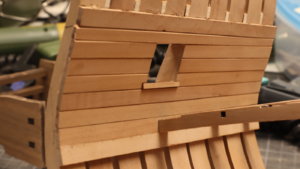
Some more small progress - finished the planking on one side - a final fine sanding of the planks will be still necessary, but I am sure, that also the timbers of contemporary ships had not every time so smooth surface
and the view with the main raider (only temporary)
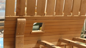
and the same gunport from outside
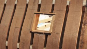
and now the other side - one more small mistake. the deck clamp was appr. 1mm to low installed - I was thinking about to leave it and to live with the wrong height or to remove. To leave it it would mean, that one plank on one side would be 1mm smaller, and also other differences between both sides.
Here it is the big advantage of wooden glue - if you made a mistake use some water, soften the glue and you can often remove the wrong piece

Now I drink a coffee and maybe later on I am able to go for one or two hours back to my Bonhomme Richard......
See you soon ......
Some more small progress - finished the planking on one side - a final fine sanding of the planks will be still necessary, but I am sure, that also the timbers of contemporary ships had not every time so smooth surface

and the view with the main raider (only temporary)

and the same gunport from outside

and now the other side - one more small mistake. the deck clamp was appr. 1mm to low installed - I was thinking about to leave it and to live with the wrong height or to remove. To leave it it would mean, that one plank on one side would be 1mm smaller, and also other differences between both sides.
Here it is the big advantage of wooden glue - if you made a mistake use some water, soften the glue and you can often remove the wrong piece

Now I drink a coffee and maybe later on I am able to go for one or two hours back to my Bonhomme Richard......
See you soon ......
Many thanks for the sketch.....Uwe
I hope this drawing makes sense.You should be able to see this on the deck plan in the monograph.To open the mortices up is a easy job with a sharp scalpel
Kind Regards
Nigel
View attachment 127373
Now I understand completely what you mean.....this way you describe I made in the HMS Triton section, cut out with a chisel.
But the structure of the Bonhomme Richard is different. I hope to show it during the next days with appropriate drawings from Boudriot or a sketch. I was also surprised when I saw it the first time......
Hello.
A clean and detailed work. It will be really helpfull. We will remain attentive and thanks for sharing.
Regards
A clean and detailed work. It will be really helpfull. We will remain attentive and thanks for sharing.
Regards
Hallo Nigel,Uwe
I hope this drawing makes sense.You should be able to see this on the deck plan in the monograph.To open the mortices up is a easy job with a sharp scalpel
Kind Regards
Nigel
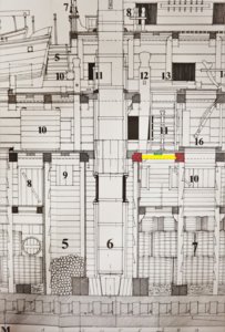
as mentioned here some excerpts from Boudriots drawings
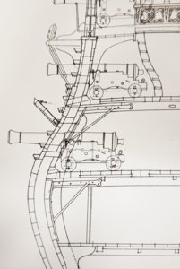
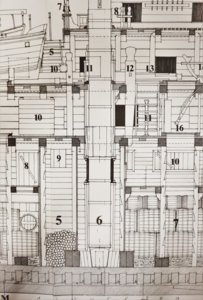
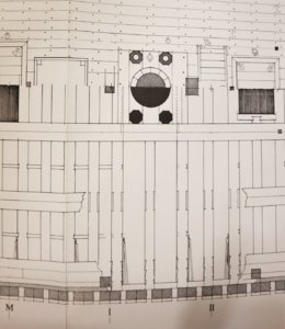
and some photos of my section as well from @neptune (sorry to borrow your photos), which will make the structure of the beam construction clear - no typical carlings and ledges as usual - also there are no lodging knees
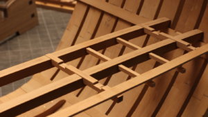
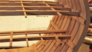
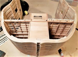
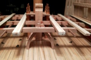
Your section is coming along nicely, and you and Nigel are right about there being a lot of discrepancies, so I am just building the kits out of the box, with a few modifications along the way, it is still a lovely kit to build and I am enjoying it thoroughly, if I was to build another one I would definitely do some of the construction differently, I would recommend this kit as value for money, and as with most kits you usually charge things, and that is the beauty of our hobby, we can build whichever way we want,
Best regards John,
Best regards John,
Hallo Nigel,
as mentioned here some excerpts from Boudriots drawings
View attachment 127478 View attachment 127479 View attachment 127480
and some photos of my section as well from @neptune (sorry to borrow your photos), which will make the structure of the beam construction clear - no typical carlings and ledges as usual - also there are no lodging knees
View attachment 127481 View attachment 127482
View attachment 127476 View attachment 127477
Uwe,I stand corrected,this is not traditional French design and I wonder how the carlings were fitted?They can only have inserted them as each deck beam was fitted,wedging the structure solid.
Kind Regards
Nigel
Gents, if I am correct the carlings are here fitted as Nigel mentioned.
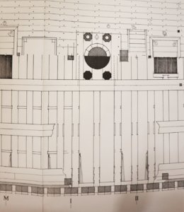
On the left side of the carling you see it is in an open slot, the next beam to the right is only a half beam on top of the carling and the carling is fitted into the next beam right to that with a closed slot.
You see open slots for the carlings in every second beam on the right side of the beam. On the left side of the beams there are none, meaning a closed slot.
Hallo Maarten,Gents, if I am correct the carlings are here fitted as Nigel mentioned.
View attachment 127561
On the left side of the carling you see it is in an open slot, the next beam to the right is only a half beam on top of the carling and the carling is fitted into the next beam right to that with a closed slot.
You see open slots for the carlings in every second beam on the right side of the beam. On the left side of the beams there are none, meaning a closed slot.
I marked here the different elements with the same color, so it is visible (I hope so) completely.
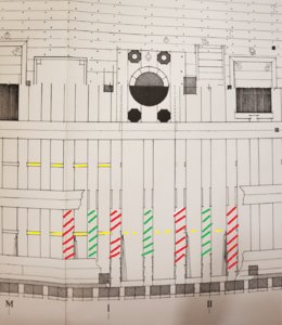
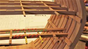
red are the full beams,
green are the main planks or "half beam" like Maarten mentioned and
yellow are the carlings
Over the weekend I had only limited time, so no big moves were possible.
But first of all many thanks for your comments and Likes I received for the last post - Thanks a lot
I finished the other side with the inner planking
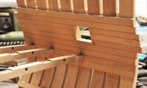
and I fixed afterwards the main raider, so I am able to proceed with the beams and the inner structure
sometimes it is good, to have also some stronger clamps.....
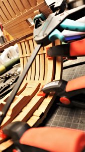
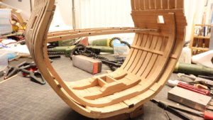
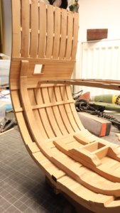
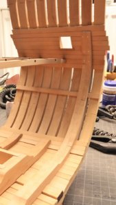
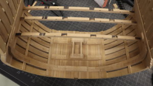
from this side (the visible spectator side) the raider fits very well, only a small gap
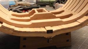
from this side not very good, the gap is much too big, but it will be not visible later on, due to the installed magazines etc.
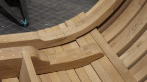
Many Thanks for your interest ......
But first of all many thanks for your comments and Likes I received for the last post - Thanks a lot
I finished the other side with the inner planking

and I fixed afterwards the main raider, so I am able to proceed with the beams and the inner structure
sometimes it is good, to have also some stronger clamps.....


from this side (the visible spectator side) the raider fits very well, only a small gap

from this side not very good, the gap is much too big, but it will be not visible later on, due to the installed magazines etc.

Many Thanks for your interest ......


