- Joined
- Aug 10, 2017
- Messages
- 1,706
- Points
- 538

History
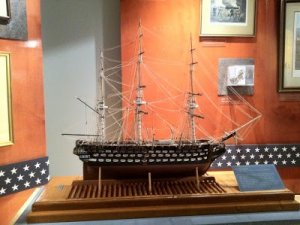
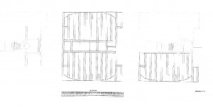
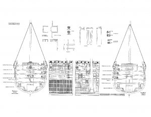
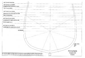
USS Pennsylvania was a four-decked 140-gun ship of the line of the United States Navy, named for the state of Pennsylvania. She was the largest sailing warship ever built for the Navy, and the equivalent of a first-rate of the British Royal Navy, but her only cruise was a single trip from Delaware Bay to Chesapeake Bay. She was just as large as the Spanish four-decked ship of the line Santisima Trinidad, built over 60 years earlier.
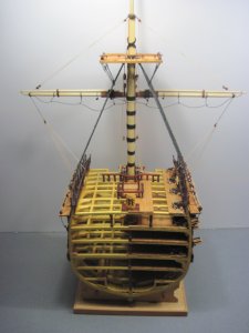
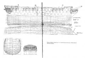
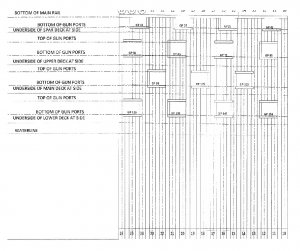
Pennsylvania was one of the "nine ships to rate not less than 74 guns each" authorized by the US Congress on 29 April 1816. She was designed and built by Samuel Humphreys in the Philadelphia Navy Yard. Her keel was laid in September 1821, but tight budgets slowed her construction, preventing her being launched until 18 July 1837. She had three complete gun decks and a flush spar-deck and her hull was pierced for 136 guns.
Exploding shell guns were replacing solid shot by the time Pennsylvania was fitting out. A Bureau of Ordnance Gun Register for 1846 records her armament as follows:
Spar deck: two 9 pounder (4 kg) cannons and one small brass swivel.
Main deck: four 8-inch (203 mm) chambered cannons received from Norfolk in 1842, and thirty-two 32 pounder (15 kg) cannons.
Middle deck: four 8-inch chambered cannons received from Norfolk in 1842 and thirty 32 pounder cannons.
Lower deck: four 8-inch chambered cannons and 28 × 32 pounder cannons.
Pennsylvania shifted from her launching site to off Chester, Pennsylvania, on 29 November 1837 and was partially manned there the following day. Only 34 of her guns were noted as having been mounted on 3 December 1837. She stood downriver for New Castle, Delaware, 9 December, to receive gun carriages and other equipment before proceeding to the Norfolk Navy Yard for coppering her hull. She departed Newcastle on 20 December 1837 and discharged the Delaware pilot on the 25th. That afternoon she sailed for the Virginia Capes. She came off the Norfolk dry dock on 2 January 1838. That day her crew transferred to Columbia.
Pennsylvania remained in ordinary until 1842 when she became a receiving ship for the Norfolk Navy Yard. She remained in the yard until 20 April 1861 when she was burned to the waterline to prevent her falling into Confederate hands.


