Vasa is looking absolutely gorgeous! Regarding your problem with turning round to square, I've found it a LOT easier to turn square into round, particularly now that you got your lathe.Hello Friends,
Thank you for the likes and encouragement since my last progress report. It is a blessing to share my work with such a kind and generous group.
In an effort to find things to do that didn't involve painting tiny metal bits (which is frankly what I should be doing right now) I turned my attention to the channels (chain wales). These were not terribly difficult to fabricate though I was concerned about getting them securely attached to the ship. My solution was a series of brass pins which appears to have worked quite well. I believe they will withstand the future stresses that will be placed on them.
View attachment 266122
View attachment 266123
View attachment 266124
View attachment 266125
I'm going to add a few more 'nails' along the edges. And the next time I make channels I'm going to make them with planks. I'm not completely satisfied with these but they are going to be largely covered up with deadeyes and rigging so I'm going to leave them as is in the name of making progress.
Next, I attempted to create chain plates and attach them to deadeyes but that was a failure so I have ordered some materials for another swing at it.
As I thought through that process, however, I realized I needed to know where the masts/cross trees would be in order to orient chain plates properly aligned with the future shrouds. That, of course, forced me to research how to shape masts. Fortunately this forum is chock-a-block full of masts and yardarms so it was not difficult to find lots of information. In the end I became convinced that Kurt's (@DARIVS ARCHITECTVS) technique on La Couronne was something I could do. Thanks also, Kurt, for your offline tutorial.
Here is what I ended up with fresh off the mini-lathe:
View attachment 266126
View attachment 266127
View attachment 266128
At the top you see my sprit mast (bowsprit). It still needs to be cut to length.
The mast in the middle is the lower element of the foremast. That odd bulge is a section that needs to be turned into a square in cross section.
The bottom dowel is one of my practice sticks for learning how to shape the masts as well as how to create the square portion (which thus far has eluded me). I suppose the best tool for this would be a mill. I tried to used a channel cutting router bit in a drill press (left) but that didn't work - and I tried to just file in the square shape (right) and that didn't work either. I'm open to your suggestions!
By the way, I found shaping these masts to be fantastically satisfying. I know you have all done this before and they aren't that big of a deal (just takes time) but having them turn out after many failed attempts on trial pieces was pretty cool.
Some of you are doing marvelous things on your respective builds. It is a joy to watch you work. The detailing is just breathtaking!
-

Win a Free Custom Engraved Brass Coin!!!
As a way to introduce our brass coins to the community, we will raffle off a free coin during the month of August. Follow link ABOVE for instructions for entering.
-

PRE-ORDER SHIPS IN SCALE TODAY!
The beloved Ships in Scale Magazine is back and charting a new course for 2026!
Discover new skills, new techniques, and new inspirations in every issue.
NOTE THAT OUR FIRST ISSUE WILL BE JAN/FEB 2026
You are using an out of date browser. It may not display this or other websites correctly.
You should upgrade or use an alternative browser.
You should upgrade or use an alternative browser.
Vasa - 1:65 DeAgostini [COMPLETED BUILD]
- Thread starter dockattner
- Start date
- Watchers 148
Good updates - your log is getting the well deserved huge support as well as tons of good information from other builders - nice indeed.
Wonderful work Paul. Always a pleasure to get back to your log and see the excellent progress.
A word of caution with your channels where they sit closely over cannon ports, and doors - you may well have trouble fitting the below-channel shroud irons as these will need to pass through the channel planks and extend to be secured to the hull. Inevitably these securing points will be close or behind some cannon doors.
This of course will likely only be an issue with the Fore and Mainmast channels as the mizzenmast channel has no cannon ports beneath.
Last edited:
Thanks Peter. The learning curve is a severe one in this hobby! But I'm learning...Wonderful work Paul. Always a pleasure to get back to your log and see the excellent progress.
A word of caution with your channels where they sit closely over cannon ports, and doors - you may well have trouble fitting the below-channel shroud irons as these will need to pass through the channel planks and extend to be secured to the hull. Inevitably these securing points will be close or behind some cannon doors.
This of course will likely only be an issue with the Fore and Mainmast channels as the mizzenmast channel has no cannon ports beneath.
I must admit, you are a great and talented student, Mon Amie! You learn fast.Thanks Peter. The learning curve is a severe one in this hobby! But I'm learning...
Paul, on the channels, you can pin them, but it’s not really necessary because the chain plates that secure the deadeyes are anchored to the hull, and thus they take the tension from the shroud lines. If anything, that tension should push the channel into the hull. The slots in the channels, the chain plates go thru, prevent the deadeyes and chain plates from creating a moment on the channel, that would want to bend it upwards. Hope that makes sense. But the pins certainly won’t hurt anything! 
You are doing a fantastic job on this ship. Keep up the great work!
On masts, I always make 4 lines, the length of the mast at 90 degrees apart to clock everything on the mast. You can use those as a guide to keep the square oriented properly. I usually file them by hand. I also use a vice to squeeze two flats parallel to one another, using the lines as a guide for clocking, squeeze just enough to compress the wood and make the small flats as a guide. Using your four lines as a guide, rotate 90 degrees and clamp again and you have your four flats clocked 90 degrees apart, to use as a guide to finish to size with a file. That’s the no power tool approach.
Thank you Dean. I was tracking with you until this part here (above). If you get a moment could you share a picture of what you are describing?I also use a vice to squeeze two flats parallel to one another, using the lines as a guide for clocking, squeeze just enough to compress the wood and make the small flats as a guide. Using your four lines as a guide, rotate 90 degrees and clamp again and you have your four flats clocked 90 degrees apart, to use as a guide to finish to size with a file.
Ok I cut a dowel to use as an example…
First mark your reference points or lines at 90 degrees apart. I use a circle template for this.
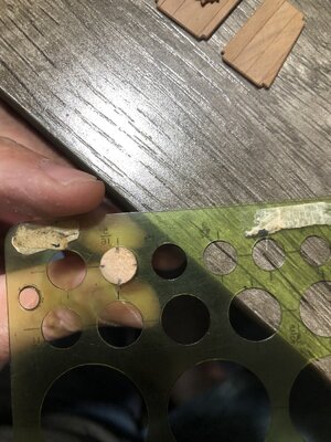
Then I put the dowel in a vice with two of the marks in line with the flats on the vice. You can use a board level with the top as a reference if you wish to be exact.
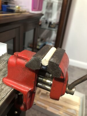
Now clamp the vice hard enough to create two flats, but don’t be overzealous!
Then rotate 90 degrees and repeat for the next two flats.
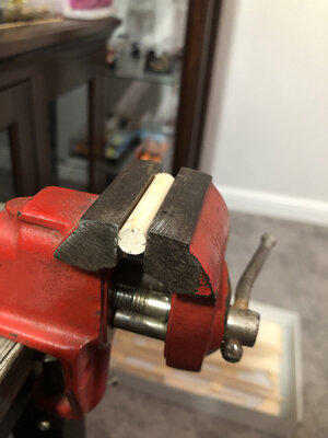
At this point you will have four flats at 90 degrees apart. This will be your reference planes or surfaces for your file. Then skate the file level with the flat until you deepen it. If it is not level, one end will be wider. You can measure and adjust. Stop when get to the width of the square you are making. Although I would do a little on each side until they start to join and you have a sharp edge.
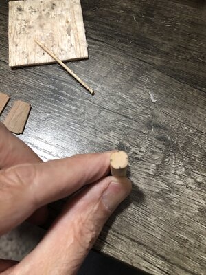
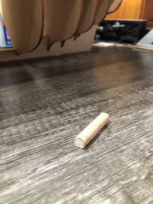
Here are the flats after clamping…
After filing…
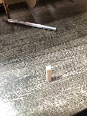
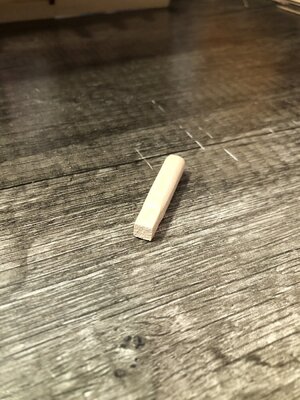
As you can see it is square, probably not perfect, but done by hand in a about 5-10 minutes.
Hope that helps!
First mark your reference points or lines at 90 degrees apart. I use a circle template for this.

Then I put the dowel in a vice with two of the marks in line with the flats on the vice. You can use a board level with the top as a reference if you wish to be exact.

Now clamp the vice hard enough to create two flats, but don’t be overzealous!
Then rotate 90 degrees and repeat for the next two flats.

At this point you will have four flats at 90 degrees apart. This will be your reference planes or surfaces for your file. Then skate the file level with the flat until you deepen it. If it is not level, one end will be wider. You can measure and adjust. Stop when get to the width of the square you are making. Although I would do a little on each side until they start to join and you have a sharp edge.
Here are the flats after clamping…


After filing…


As you can see it is square, probably not perfect, but done by hand in a about 5-10 minutes.
Hope that helps!
Kurt Konrath
Kurt Konrath
I would assume the “seats of ease” aka Head are open bottom and empty overboard.
Early passenger trains those up till the 70’s had open dump seats as well. That is why they had signs “ do not use in station”. And hobos knew not to stay under a train bridge!
Early passenger trains those up till the 70’s had open dump seats as well. That is why they had signs “ do not use in station”. And hobos knew not to stay under a train bridge!
- Joined
- Oct 9, 2020
- Messages
- 2,238
- Points
- 488

now that is skill. I compensate for my lack of skill by using power tools. But, I like power tools so it's all good I guess.Ok I cut a dowel to use as an example…
First mark your reference points or lines at 90 degrees apart. I use a circle template for this.
View attachment 266308
Then I put the dowel in a vice with two of the marks in line with the flats on the vice. You can use a board level with the top as a reference if you wish to be exact.
View attachment 266309
Now clamp the vice hard enough to create two flats, but don’t be overzealous!
Then rotate 90 degrees and repeat for the next two flats.
View attachment 266310
At this point you will have four flats at 90 degrees apart. This will be your reference planes or surfaces for your file. Then skate the file level with the flat until you deepen it. If it is not level, one end will be wider. You can measure and adjust. Stop when get to the width of the square you are making. Although I would do a little on each side until they start to join and you have a sharp edge.
Here are the flats after clamping…
View attachment 266318
View attachment 266319
After filing…
View attachment 266320View attachment 266321
As you can see it is square, probably not perfect, but done by hand in a about 5-10 minutes.
Hope that helps!
- Joined
- Sep 3, 2021
- Messages
- 5,199
- Points
- 738

Very usable! Thanks for sharing.As you can see it is square, probably not perfect, but done by hand in a about 5-10 minutes.
Hope that helps!

- Joined
- May 27, 2021
- Messages
- 222
- Points
- 88

Well, Paul, I believe this is real life, and now we ARE friends. I like the childlike simplicity of “Oh, you love STARWARS?!! ME TOO! Let’s blow-up the Millennium Falcon!” Common interest, common ground, and humor to boot!
In answer to your question, the channels are designed to shed water, so they should be tapered in cross-section - thickest where they join the hull, and more likely parallel to the surface of the water. I’m not pulling all of this from Witsen, or any other early treatise on shipbuilding, but my own reasoned observations of original ship models.
Speaking to my point, yesterday, about close observation of original dockyard models, check out this video that offers granular clarity of every last detail:
Unquestionably, all three are works of art, but.. they’re not perfect. Perfection is a fiction of the obsessive compulsive set, like myself, who needlessly flagellate ourselves because our hand-painted lines wavered a little TOO much in their overall con
Paul, on the channels, you can pin them, but it’s not really necessary because the chain plates that secure the deadeyes are anchored to the hull, and thus they take the tension from the shroud lines. If anything, that tension should push the channel into the hull. The slots in the channels, the chain plates go thru, prevent the deadeyes and chain plates from creating a moment on the channel, that would want to bend it upwards. Hope that makes sense. But the pins certainly won’t hurt anything!
You are doing a fantastic job on this ship. Keep up the great work!
On masts, I always make 4 lines, the length of the mast at 90 degrees apart to clock everything on the mast. You can use those as a guide to keep the square oriented properly. I usually file them by hand. I also use a vice to squeeze two flats parallel to one another, using the lines as a guide for clocking, squeeze just enough to compress the wood and make the small flats as a guide. Using your four lines as a guide, rotate 90 degrees and clamp again and you have your four flats clocked 90 degrees apart, to use as a guide to finish to size with a file. That’s the no power tool approach.
- Joined
- May 27, 2021
- Messages
- 222
- Points
- 88

....What....? ... to early,,, more coffee....Paul, on the channels, you can pin them, but it’s not really necessary because the chain plates that secure the deadeyes are anchored to the hull, and thus they take the tension from the shroud lines. If anything, that tension should push the channel into the hull. The slots in the channels, the chain plates go thru, prevent the deadeyes and chain plates from creating a moment on the channel, that would want to bend it upwards. Hope that makes sense. But the pins certainly won’t hurt anything!
You are doing a fantastic job on this ship. Keep up the great work!
On masts, I always make 4 lines, the length of the mast at 90 degrees apart to clock everything on the mast. You can use those as a guide to keep the square oriented properly. I usually file them by hand. I also use a vice to squeeze two flats parallel to one another, using the lines as a guide for clocking, squeeze just enough to compress the wood and make the small flats as a guide. Using your four lines as a guide, rotate 90 degrees and clamp again and you have your four flats clocked 90 degrees apart, to use as a guide to finish to size with a file. That’s the no power tool approach.
Dean, thank you very much for posting this thoughtfully designed and careful process. My square section is larger than my round section but there is no reason I could not apply this approach once I have tapered the masts (as I showed in an earlier post)...Ok I cut a dowel to use as an example…
First mark your reference points or lines at 90 degrees apart. I use a circle template for this.
View attachment 266308
Then I put the dowel in a vice with two of the marks in line with the flats on the vice. You can use a board level with the top as a reference if you wish to be exact.
View attachment 266309
Now clamp the vice hard enough to create two flats, but don’t be overzealous!
Then rotate 90 degrees and repeat for the next two flats.
View attachment 266310
At this point you will have four flats at 90 degrees apart. This will be your reference planes or surfaces for your file. Then skate the file level with the flat until you deepen it. If it is not level, one end will be wider. You can measure and adjust. Stop when get to the width of the square you are making. Although I would do a little on each side until they start to join and you have a sharp edge.
Here are the flats after clamping…
View attachment 266318
View attachment 266319
After filing…
View attachment 266320View attachment 266321
As you can see it is square, probably not perfect, but done by hand in a about 5-10 minutes.
Hope that helps!
You're welcome Paul. Adding flats after turning helps ensure you only put flats on the larger diameter. Or add the flats in the area you need and then turn the mast down. Either way you're fine!Dean, thank you very much for posting this thoughtfully designed and careful process. My square section is larger than my round section but there is no reason I could not apply this approach once I have tapered the masts (as I showed in an earlier post)...
I'm sure none of you have slept well wondering how Paul will turn round stock into square...so I thought I should give you a brief update.
But first, I want to share my appreciation for the many good thoughts and suggestions (start with square stock / buy a mill / etc.). I will keep those excellent ideas in mind for a future build. Thanks, especially, to Dean who took the time to post his excellent tutorial.
I gave your technique a whirl Dean and it worked pretty well. The aspect that ultimately caused me to keep searching is that my mast blanks are hardwood and I wasn't getting a very prominent flat to use as a guide for the file work.
I ended up with a simple solution that I'll share in case anyone finds themselves in a similar spot.
You have seen my rough turned masts:
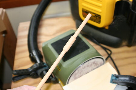
I began by sanding one surface flat on a disc sander (shy of the final goal):
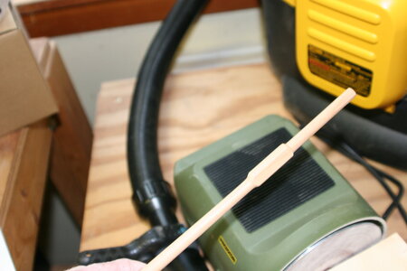
I then turned the rod so the flat part was sitting on the guide table and sanded the next surface (perfect 90 degrees with no fuss):
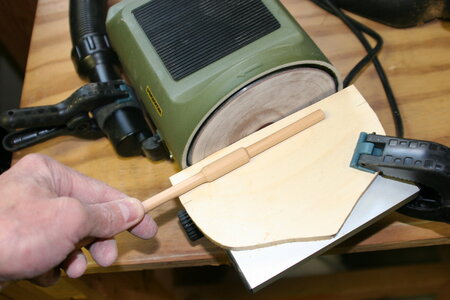
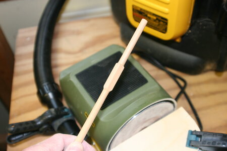
I then repeated those steps on the remaining surfaces and then snuck up on the final position of the square (I wanted the flat area to run perfectly into the round area at the apex of the curve):
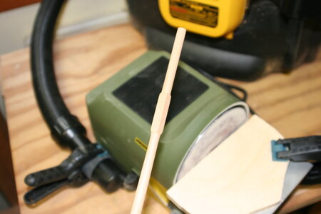
Confession: several times I overshot my goal and needed to take the part back to the lathe for refining.
Anyway, not exactly rocket science, but this worked nicely in my hands (and with the tools I have on hand).
One more thing. I mentioned that I adopted Kurt's (aka Mr. Destructo - if you follow his build log you know what I mean) mast tapering technique. Basically he uses opposing sanding blocks to keep the piece from breaking as the lathe spins. Just for fun - here is a proof of concept photo:
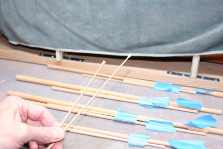
The shorter piece is 120 mm of 4 mm stock tapered to 1.7 mm (still need to shape a ball on the top). The longer piece is nearly 200 mm long and tapers to 2.0 mm. Pretty cool.
As I mentioned earlier I am finding tapering these masts to be fantastically satisfying. Maybe there won't be a future ship build - I feel some woodturning in my future!
Thanks for stopping by! As always, I am humbled by your interest in my work.
But first, I want to share my appreciation for the many good thoughts and suggestions (start with square stock / buy a mill / etc.). I will keep those excellent ideas in mind for a future build. Thanks, especially, to Dean who took the time to post his excellent tutorial.
I gave your technique a whirl Dean and it worked pretty well. The aspect that ultimately caused me to keep searching is that my mast blanks are hardwood and I wasn't getting a very prominent flat to use as a guide for the file work.
I ended up with a simple solution that I'll share in case anyone finds themselves in a similar spot.
You have seen my rough turned masts:

I began by sanding one surface flat on a disc sander (shy of the final goal):

I then turned the rod so the flat part was sitting on the guide table and sanded the next surface (perfect 90 degrees with no fuss):


I then repeated those steps on the remaining surfaces and then snuck up on the final position of the square (I wanted the flat area to run perfectly into the round area at the apex of the curve):

Confession: several times I overshot my goal and needed to take the part back to the lathe for refining.
Anyway, not exactly rocket science, but this worked nicely in my hands (and with the tools I have on hand).
One more thing. I mentioned that I adopted Kurt's (aka Mr. Destructo - if you follow his build log you know what I mean) mast tapering technique. Basically he uses opposing sanding blocks to keep the piece from breaking as the lathe spins. Just for fun - here is a proof of concept photo:

The shorter piece is 120 mm of 4 mm stock tapered to 1.7 mm (still need to shape a ball on the top). The longer piece is nearly 200 mm long and tapers to 2.0 mm. Pretty cool.
As I mentioned earlier I am finding tapering these masts to be fantastically satisfying. Maybe there won't be a future ship build - I feel some woodturning in my future!
Thanks for stopping by! As always, I am humbled by your interest in my work.
Try this video...
Or this method
Hi Paul- I slept rather well. Your log and contributions from Dean etc are invaluable to me for when I get to my masts. Thanks. PS it appears I am going to have to invest in some of the magic machinery you have. Admiral may need some convincing tho.I'm sure none of you have slept well wondering how Paul will turn round stock into square...so I thought I should give you a brief update.
But first, I want to share my appreciation for the many good thoughts and suggestions (start with square stock / buy a mill / etc.). I will keep those excellent ideas in mind for a future build. Thanks, especially, to Dean who took the time to post his excellent tutorial.
I gave your technique a whirl Dean and it worked pretty well. The aspect that ultimately caused me to keep searching is that my mast blanks are hardwood and I wasn't getting a very prominent flat to use as a guide for the file work.
I ended up with a simple solution that I'll share in case anyone finds themselves in a similar spot.
You have seen my rough turned masts:
View attachment 267166
I began by sanding one surface flat on a disc sander (shy of the final goal):
View attachment 267167
I then turned the rod so the flat part was sitting on the guide table and sanded the next surface (perfect 90 degrees with no fuss):
View attachment 267168
View attachment 267169
I then repeated those steps on the remaining surfaces and then snuck up on the final position of the square (I wanted the flat area to run perfectly into the round area at the apex of the curve):
View attachment 267170
Confession: several times I overshot my goal and needed to take the part back to the lathe for refining.
Anyway, not exactly rocket science, but this worked nicely in my hands (and with the tools I have on hand).
One more thing. I mentioned that I adopted Kurt's (aka Mr. Destructo - if you follow his build log you know what I mean) mast tapering technique. Basically he uses opposing sanding blocks to keep the piece from breaking as the lathe spins. Just for fun - here is a proof of concept photo:
View attachment 267171
The shorter piece is 120 mm of 4 mm stock tapered to 1.7 mm (still need to shape a ball on the top). The longer piece is nearly 200 mm long and tapers to 2.0 mm. Pretty cool.
As I mentioned earlier I am finding tapering these masts to be fantastically satisfying. Maybe there won't be a future ship build - I feel some woodturning in my future!
Thanks for stopping by! As always, I am humbled by your interest in my work.
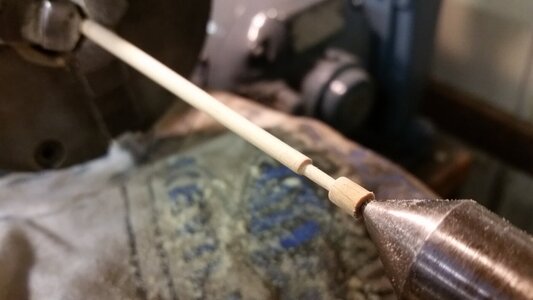
I have a small suggestion, Paul. You might already know this. If you even need to make a sharp step in the yard, or reduce the long taper shown on your spun mast above to a narrower and sharper transition in diameter, use a mill file and slowly draw it with light pressure to shape the wood. Below is an example of what will be a yard arm. The narrow end has a sharp transition that was achieved with many light strokes of a jewelers file. If you try to make hard cuts, the piece will crack at the corner where the section that ride on the center and the narrow part meet. For this yard, the larger diameter part that ride on the center will be cut off and discarded after it is removed from the lathe. You can sculpt wood into detailed shapes if you are slow and careful with the file. You can use a round file for radii or a flat or triangular file for sharp corners. If the work is just too delicate, say at a diameter of less than 3mm, you can avoid risk, take the piece off the lathe, and file the inside corners by hand.View attachment 266127
View attachment 266128
At the top you see my sprit mast (bowsprit). It still needs to be cut to length.
The mast in the middle is the lower element of the foremast. That odd bulge is a section that needs to be turned into a square in cross section.
The bottom dowel is one of my practice sticks for learning how to shape the masts as well as how to create the square portion (which thus far has eluded me). I suppose the best tool for this would be a mill. I tried to used a channel cutting router bit in a drill press (left) but that didn't work - and I tried to just file in the square shape (right) and that didn't work either. I'm open to your suggestions!
By the way, I found shaping these masts to be fantastically satisfying. I know you have all done this before and they aren't that big of a deal (just takes time) but having them turn out after many failed attempts on trial pieces was pretty cool.
Some of you are doing marvelous things on your respective builds. It is a joy to watch you work. The detailing is just breathtaking!
