Vasa Build Log - Billing Boats - Scale 1/75 [COMPLETED BUILD]

David,

For those not aware, in my research of build logs, I came across David Teel's magnificent Vasa and in one of his posts he described the use of various rigging diagrams to get his ropes and rig correct. One of the items were the Rigging Plans then issued by Vasamuseet. I believe they have since ceased issuing these, and so, with communication to David, he very generously sent his museum Rigging Plans to me for use in my build. I cannot express my gratitude for your doing this David - especially as I live on the other side (literally) of the world!!

To answer your question regarding the detail of sculptures and the weaponry shown from your drawings. In the previous posts, we discussed the use of spears/staves being held by the guards flanking the Captain's Cabin. This issue was highlighted by Foxtrott (Alexander) where he responded 'As far as I remember, only the two outer knights carry spears. (?)' To clarify this somewhat, in your drawings David, ALL the guards appear to have been shown with spears. I attach a photo below taken from the Vasamuseet drawings.

IMG_4663.JPG

Regards,

Peter G.
 

Attachments

  • IMG_9429.JPG
    IMG_9429.JPG
    191.9 KB · Views: 33
And so we move to the deck and topside fittings. In particular, the cannons. A lot has been provided in other build logs about the cannons for the Vasa. Their design was of bronze with ornamentation and relatively conventional trucks as below:

Cannon.jpg

The cannons provided by Billing Boats are of four types:

a) The truncated barrels only for the below deck installations. These have been accounted for by 'artificial' gun carriages installed during planking of the hull. I have not placed them in the ship yet, but their positions have been drilled and are ready for fitting. The hull gun doors will be described in a later post.

b) The main weatherdeck cannons which are mounted on slightly larger carriages. These are mounted along the foredeck areas and there are six of them. Interestingly these guns have not been supplied with barrels that are any different from the slightly smaller carriage mounts to be placed amidships.

c) The midship cannons use slightly smaller carriages but the same rope rigging and load arrangements.

d) Two smaller upper, stern weatherdeck carronades which are provided with gun carriages that appear to be similar in design to field artillery. These I did not like with their large wheels and unwieldly shaped cannon carriage frames. So, I scratched two mounts for these smaller barrels that I am much happier with.

One difficulty in modelling the cannons related to the ornamentation of the barrels. The barrels supplied by Billings are brass, but with plain turnings and no ornaments. So, I had the choice of buying a set of say, Amati cannons with ornamentation (as similar to English 18th century ships), or attempting to modify the ones provided. A third option was to cast new cannons, probably in resin. I looked into this and may still attempt it, but they are small, and I haven't done it before. My solution at this stage, was to solder each barrel with some metal at the rear that I then scribed/engraved with some 'make-do' ornamentation. Small and time consuming work to try and add the crest seen on the cannon above. The two handles, I attempted by soldering wire etc but it proved too difficult and made a mess of the barrel (so I scrapped that idea!!).

Once I had the carriages made and together, I mounted the barrels, decorated them and added the various metal straps (at the wheels, four, and over the barrel axles). Where necessary copper nails were inserted to hold these but where I would normally paint these black, I painted the heads silver so that they can be seen against the black metal of the steelwork on the carriages. Below is a part finished carriage and barrel. Note the truck wheels constructed of brass tubing cut thinly and then placed over and impressed into soft timber to make the inner wheel. This gave a good wheel appearance although much of the detail was lost after painting of the brass and staining the timber. Axles are of brass and set into grooves cut in the base of the carriage truck frame. This gave the correct height which was adjusted for the various cannon port openings on deck. Some latitude is provided by the angle of the gun barrel to be centred in the porthole, and once secured, a drop of CA glue allowed the cannon barrel to be correctly placed in appearance from the outside.

IMG_4606.JPG

I had stained the carriages a dark brown/black which still showed the grain of the timber without giving a 'paint-like' finish. The most time-consuming part of mounting the cannons, was the rope rigging. The recoil ropes were OK as they only required hooks at each end (which I fashioned out of bent copper wire) and screweyes into the main deck thwarts. The tricky part were the pulleyed rigging used for reloading a rolled gun inboard. Initially, I was not happy with the size of the pulleys supplied for this, they seemed too large. I scratched some smaller pulleys, about 3 mm, which I was happier with. As there were only 14 weatherdeck guns, times 2 x 2 for each side of the carriage, that was 56 pulleys required. Then came the rope to be used. I was not happy with the thinnest of the Billing Boat kit supply. It was too string-like, white and hairy (even if bees-waxed) - not realistic for this application. To overcome this, I then started researching the use of a ropewalk. This is a topic for another post, but needless to stay, I have had some success with a home-grown ropewalk that I can make assorted ropes of varying thicknesses and colours etc. This, eventually is what I used for the rigging ropes of my cannons. Below I show some pictures of the mounted cannons with their rigging.

IMG_4619.JPG

For each cannon I have added rope coils that are hanging from the rear of the each side of the carriages. I may have to tone-down the crests of each cannon. The contrast with the black seems a bit strong. Note too that the secured thwart ends of the reloading ropes on the upper screweyes are attached by a thin, shaped piece of toothpick. These timber locks were used on the 'real' ship for quick release of the cannon if required. To get them to scale was not a problem, but threading them through a secured loop of the reloading rope loops was time consuming.

More soon.

Time elapsed: 1160 hours

Best Regards,

Peter G.
 
Many thanks for your comments gentlemen - Charles, Jan and Michael.

I am aware of the "runaway" ropes on the rudder. I do not have Landstrom (although I would love to have it in my collection). The ropes are documented elsewhere and are a feature that I will definately add in the future. At this stage, I am attempting to complete all the 'fixed' deck/hull fittings without adding parts that I might catch on or cause damage to if I got caught.

It is interesting how many Vasa models you look at (in build logs or elsewhere) where these ropes have been replaced with chains, as was the norm on later sailing ships (eg Cutty Sark). In these cases of course, the chains were often used to actually steer the ship and control the rudder rather than as a safety precaution for losing the rudder.

Actually, as I study it a bit further, I am a bit confused by the rope rigging used with the rudder. Note that there are the two ropes that come out of the portholes in the stern. However there is a third rope (as seen in Landstrom's drawing, where it parallels the leading edge of the rudder and then diverts slightly aft to be attached to the rudder just above the waterline. Is this rope repeated on both sides of the rudder and do they (it ?) form the other ends of the ropes that come out of the portholes?

Best Regards,

Peter G.
Hi Peter
The takles are fastened by a stopper knot at both sides of the rudder. Leads through a hole in the rudder and goes up through the opening for the tiller into the ship.
One line starbord and one line at the port side.
So you need two boreholes in the rudder as you see in Landström's drawing.
If you alter this at the rudder you could also think about the fastenings of the pintles
They are mounted flush to the frontside of the rudder at the Vasa. The picture, you posted yesterday shows a gap between the rudder and the sternpost which is pretty broad.

Cheers Alexander
 
Last edited:
Me again, Peter.
The drawing of Vasas stern is very nice. I got it as a poster 1978 and it embellishs now my workshop.
It's well done but there are some mistakes which misleaded me too. The Herculeses changeged their position. At the real Vasa the young Hercules is now positined at starboard.
Of course the two tritons at the top of the stern are missing.
Here a photograph of the upper stern.

Cheers Alexander f187t1597p27154n2.jpg
 
Many thanks Charles. Your compliments are always well received.

Michael,

I have admired your build for a long time and have been absolutely impressed with you abilities to 'scratch' something when the kit falls short of the research. Your attention to fine detail is simply magnificent (https://shipsofscale.com/sosforums/threads/corel-vasa-bashed.2541/). I know you (and many others) have made comments about the Corel kit figures and other design faults previously. To give them some credit of course, their Vasa kit was based on knowledge as it was in, what, the 1980's (?), before Fred Hocker and the research team studied the ship in such depth. Updating such a kit, as you say, would probably not be cost-effective, but some effort would improve the situation.

Unfortunately I did not have the pleasure of meeting Mr Hocker when I visited in July 2017. It must have been a wonderful and educational experience. My visit to the museum in Stockholm (during a Baltic cruise), was the inspiration for my current build. I do however have Fred's first book 'Vasa I - The Archeology of a Warship of 1628' and am very much looking forward to the publication of Vasa II. Building the Vasa of course is such a rare privilege in that the original ship is now still in existence and providing us with so much detailed research to help detail our models!! The Vasa of course is not the only ship to still exist in its original form (others such as the Mary Rose, Victory, Cutty Sark etc etc all still exist), but it has the unique story of having been raised with over 90% of its hull/features etc still intact (thanks to the low oxygen of the Baltic Sea) and it did sink in April, 1628. It was submerged for 333 years so its condition is miraculous when seen in the museum. The restoration efforts by the Vasamuseet team too should not go unrecognised. It's their efforts that has allowed the ship to be in its present, wonderful, condition.

Its a great story and the history is just as interesting. It's no wonder that our ship modeller's interest is alive and well!!

Thanks again for your comments,

Best Regards,

Peter G.
Peter - thanks for your overly kind remarks. So appreciated, and adding my link was beyond Nice!!
In retrospect I started that Corel example when I knew almost nothing about the ship - it was later during the build that I studied and tried to fix the So Many errors in the very old Corel issue. My results are not even close to the quality of work that I have seen from builders of this ship currently being built, or from other much more accurate kits that are now available.
Again thanks -- so nice of you !!

Sincerely,
 
Thank you Michael and Alexander.

I apologise, but I am still confused by the rudder rope tackle and where the ropes ran. Reading what you have written, there are FOUR separate ropes which sometimes emerge from the ship's stern at about the level of the gunports/rope ports.

1. Two of these ('runaway') ropes come up the inner length of the rudder (from just above the waterline), where they have stopper knots passing through holes in the rudder (as shown in Landstrom's drawing and as suggested by you, Alexander). The other ends of these two ropes pass and are presumably secured, inside the hull with the ropes entering the ship near the tiller arm.

Note too, in Landstrom's book drawing which you show in your post, he has also shown a rope loop that passes around this vertical rope (at least on the starboard side), which exits and returns from the gunport. It emerges from the gunport (not the rope ports) as in Landstrom's drawing it is shown to be relatively long and rectangular PLUS, further starboard, there is an indication of where the rope porthole is mounted. I have not seen or noticed this before on any other model.

2. Sometimes there are two additional ropes which emerge from the rope ports adjacent the gunports and these appear to extend to the rudder and are attached. I have seen this in some models (eg Janssen's) as shown as black ropes in the photo below. If these ropes were used, I am unsure how they were attached to the rudder and whether they were used as well as the previously described two ropes.

Stern_rudder.jpg

Two additional ropes on occasion are seen to emerge from the port and starboard side stern portholes (using the portholes ABOVE the height to the stern gunports), but these usually are suggested as mooring lines (eg from the book by Freedman with illustrations by Low, see picture below). These are not in conflict with the two sets of two ropes above which appear to have been used with the safety of the rudder only.

Moored.jpg

Finally, Alexander, I appreciate your comments regarding the rudder pintles and the rudder gap. I have fitted them exactly as per the Billing Boat kit pintles and gudgeons. I agree that the gap between the rudder leading edge and the rear of the hull fairing is perhaps too wide. To fix this is quite a big job as I will have to remove either the pintles on the ship or on the rudder. Probably the simplest would be to remove the rudder and its brasswork only, increase the depth of the spaces already cut in the rudder edge and then set the rudder closer to the ship. I would then also drill the stopper holes for the 'runaway' ropes.

Regards,

Peter G.
 
Last edited:
Alexander,

Your attention to detail is excellent, as is that photo of the stern of the Vasa in the museum. The location and 'ages' of the two Hercules, I will now take on board and amend the sculptures at the bases of the corner 'totems' as you have indicated. The younger on the starboard side and the older, with crown, on the port side. The plastic rendering in the kit has these two Hercules as opposite in their facing, but the same in their shape.

Just to clarify, I assume your comment 'Of course the two tritons at the top of the stern are missing. ' is referring to the carved timber which wraps around the very top edge of the stern timbers, from port over to starbord. The regular, rolled carving below the tritons is included but that is where it stops in the kit. Above that, the surface is smooth with no carving. In the Billing Kit, this carving is not present and to create it will be difficult. I will probably have a try, but it won't be easy!!!

Regards,

Peter G.
 
On deck, some of the furniture has to be done...

Firstly, the knightheads. In total there are seven knightheads, used on the Vasa for belaying and running ropes where tension, even back to the capstan may be required. Each knighthead has one, two or four pulleys mounted within its square or block lower portion and then above this is a carved head. These heads on Vasa were of the heads of Roman soldiers, some attractive damsels, or a dark, swarthy gentlemen with a turban. Photos of some of these are shown below:

Knight_2.jpg

Knight_1.jpg

Notice in the photo directly above, that there are four pulleys mounted in the righthand block near deck. I have attempted to carve these figures and only when I had a head I was happy with, did I bore the holes below for the pulleys. The carving was more prone to disaster, so this was done first, and there were a few disasters along the way!! Eventually I managed to get six of the seven constructed, but the seventh was the four pulley block and this needed a different approach. I was unable to successfully drill, bore and file four separate pulley openings without cutting the very thin layer of wood between the pulley wood walls. I do not have a milling machine, but even if I did, at this scale, I think the wood would still tear when less than 1.0 mm thick. My solution was to carve three pulley openings and then add a fourth by laminating a piece of timber to one side which had already been indented for the pulley opening. This proved successful and the result is shown below with my turbaned-headed gentleman. I have stained the outer sides of the knightheads but have missed the pulley openings, so I will have to go back and stain these too - whoops - I only just noticed it from the photo.

Knights.jpg

The next items I tackled where the 14 sheet handling pulleys which are mounted on thwarts between gun carriages of the weather deck. Although not obvious, these can be seen along the port side of the Vasa in the photo above. These were made of laminated Obechi wood pieces, glued together and then cut at appropriate locations before inserting pulleys and axles. Below shows a picture of the laminating of the pieces and below that, the final sheet pulley assemblies. The pulley wheels were of brass and supplied with the Billing Boat kit.

IMG_4607.JPG

IMG_4618.JPG

A copper nail above the pulley axle end was also added as a means of securing to the thwart timbers. The pulleys were mounted along each side of the ship, approximately between each cannon carriage where the sheets could run freely from the yards and upper rigging.

Time elapsed: 1175 hours

Regards,

Peter G.
 
Hi Peter
Landström's pictures show the situation of the two rudder pendants very good. Guest lines for boats or mooring lines will be shown only at an diorama, I think.

But also the rudder pendants are not really necessary at am model of this scale - just an interesting detail.
Also think well at changes to the rudder, because something could easily be destroyed. If you do, I could give you better drawings of the rudder.

The dark brown colour of the gun- carriages is very fine. Fred Hocker told me, the carriages where painted black. So I also choose a sepia brown at my model to avoid the hard contrast of the pure black. Similar as your carriages.

Cheers Alexander
 
Last edited:
Many thanks Michael and Alexander,

It's interesting how individual's come to their own conclusions about how things are done historically. I think you are correct. I think regarding the rudder safety ropes, Landstrom got it right in his book. I intend to add the two ropes that run vertically up the length of the rudder and then enter the hull near the tiller.

The other two ropes which many have modelled as emerging from the rope ports on the lower part of the stern, may have been used for rudder safety, but of course, Vasa never ;went to sea', so we are unlikely to ever know. Mooring lines or towing dinghys etc would also be uses for these and the higher portholes, but again, there is unlikely to be any written documentation on this.

The internal section diagram as you show in your post Michael is very interesting. In particular, what caught my eye was the mechanical arrangement of the tiller operation for the helmsman in his lowered deck position. His steering 'cabin', has a hinged lever which on a short length arm, is coupled to the very long extension length of the tiller. If you think about the mechanics of such an arrangement, large helsman movement of his lever, would only cause VERY small movement at the rudder, albeit very powerful with the leverage (turning moment) available. While I am sure this is correct, it would seem that with so little rudder rotation available to the helmsman, getting the ship to turn would have been a VERY slow and painful process - Hardly a nimble warship!! In fact, the rudder with this arrangement, I could not anticipate to have any more than about 2-3 degrees of rotation. Interesting.

Alexander - Thank you too for your comments on the cannons and gun carriages.

Regards,

Peter G.
 
I thought it might be time to attempt the chainplates along the flanks of the ship. It is interesting when reviewing pictures of the real Vasa, that two things stand out:

1. The positioning of the mix of chainplate positions for the deadeyes AND brace pulleys is located such as to allow a minimal, but clear view from the various gunports and cannons to fire clearly through the lines. The clearances are not large, but enough to allow a clear shot to pass through where no offset or angle of shooting is used (which would have been the norm). Additionally, in some instances, particularly where the chainplate is serving a mast with significant rake angle, the deadeye or brace line may be positioned directly in front of a gun, but the angle of the line up to the mast is such that it provides gun shot clearance.

2. The deadeyes themselves in most instances, especially for the larger, low chainplates, are NOT round. They are shaped like an eccentric 'egg' with the upper curvature significantly broader and of larger radius than the lower, curved bottom of the deadeye.

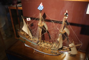
These two points are indicated in the photograph of the museum Vasa below. This picture is of the mainmast chainplate:

IMG_6665.JPG

Even the aft, mizzenmast chainplates with their smaller deadeyes are not round, but shaped like an 'egg', see below. Note too that the braceline attached to this chainplate has its own strop attached to the top wale beneath. Strops too, made of iron on the real ship, may be angled considerably to account for their individual alignment of their deadeye and the mast rake angle.

IMG_6695.JPG

So, to simulate the above shapes, I have decided to sand every one of my deadeyes to this egg-like shape (wow, what was I thinking)!!! There are a LOT of them. However, job complete. Following the sanding was some mild wash staining with examples of a few completed below:

IMG_4599.JPG

I experimented with the steel securing straps that surround the deadeyes and the most successful, assembly line approach I could devise, was to create a rounded piece of broomstick, which I cut down on one end, shaped and drilled a hole into for some medium weight copper wire. I then inserted one end of the wire into the hole and wound the wire once around the shape I had carved. Using my thumb to push the wire into the indented shape, I then cut the wire, removed it from the broomstick jig, and soldered the ends. These then formed the perfect shape and size for all my large deadeyes. The smaller deadeyes just required the same process (at the other end of my 6" broomstick), and I then had all the metal strap surrounds for the deadeyes with the extension shape beneath to attach to the brass strop.

IMG_4597.JPG

I used Brass Blackit to colour the copper wire and job done. The wire surrounds tightly fitted over the deadeyes and then with pliers I simply squeezed them a little, and the wires were secure and the correct shape. I broke a few solder joints with the pressure applied but these were easily repaired.

Adding the deadeyes to the brass strips supplied by the Billing kit, was a simple bend and cut after measuring, and then a scale railroad tie was used to secure the deadeye strop to the top wale of the hull. Each nail was pre-drilled to ensure it would go in accurately and straight. The brass strip coming up from the wale was bent around the chainplate, cut to length and angled within its groove cut in the chainplate timber. Positioning with the correct angle was important. To do this, I temporarily inserted the masts and ran a stringline from the top, lower section to the deadeyes to get the alignment and ensure correct clearance for any gunports.

IMG_4592.JPG

Note too - In the picture above, if you were wondering, I have placed green masking tape over the hatches - I am sick of dropping 'stuff' into inaccessible places and this stops that. when the hatch covers are placed on, the problem goes away, but they do catch a lot of dust!!

Once all deadeyes and brace lines were attached, a thin cover strip was glued over the strops to hold them in place and retain their angles. I tried really hard to give reasonable gunport clearance. For a couple of cases, I would not like to have been the gun aimer, especially in firing anything other than straight ahead!! I did have to change the number of deadeyes and brace lines from those recommended from the Billing kit Rigging Plan. I preferred the Museum Rigging Plan and will be adhering more strictly to this, than that of the kit.

Time Elapsed: 1235 hours

Regards,

Peter G.
 
Last edited:
Hi Peter,
Many thanks Michael and Alexander,

It's interesting how individual's come to their own conclusions about how things are done historically. I think you are correct. I think regarding the rudder safety ropes, Landstrom got it right in his book. I intend to add the two ropes that run vertically up the length of the rudder and then enter the hull near the tiller.

The other two ropes which many have modelled as emerging from the rope ports on the lower part of the stern, may have been used for rudder safety, but of course, Vasa never ;went to sea', so we are unlikely to ever know. Mooring lines or towing dinghys etc would also be uses for these and the higher portholes, but again, there is unlikely to be any written documentation on this.

The internal section diagram as you show in your post Michael is very interesting. In particular, what caught my eye was the mechanical arrangement of the tiller operation for the helmsman in his lowered deck position. His steering 'cabin', has a hinged lever which on a short length arm, is coupled to the very long extension length of the tiller. If you think about the mechanics of such an arrangement, large helsman movement of his lever, would only cause VERY small movement at the rudder, albeit very powerful with the leverage (turning moment) available. While I am sure this is correct, it would seem that with so little rudder rotation available to the helmsman, getting the ship to turn would have been a VERY slow and painful process - Hardly a nimble warship!! In fact, the rudder with this arrangement, I could not anticipate to have any more than about 2-3 degrees of rotation. Interesting.

Alexander - Thank you too for your comments on the cannons and gun carriages.

Regards,

Peter G.
Hi Peter,

The rudder was not used to steer the ship as now a days. The ship was steered with the sails and only slightly corrected with the rudder.
Love your Vasa, build the billing boats kit my self some 35 years ago when she was still blue and gold. This red and baroque coloring looks far better.
 
Hi Peter,
Hi Peter,

The rudder was not used to steer the ship as now a days. The ship was steered with the sails and only slightly corrected with the rudder.
Love your Vasa, build the billing boats kit my self some 35 years ago when she was still blue and gold. This red and baroque coloring looks far better.
Ja Ja - the good old time, when the Vasa was still blue - Fred Hocker and his team changed the world (of kit-producers) completely, when they published the changed color schema.
Very good work btw
 
I was always captivated by the Wasa.
Mist my chance to see the museum a few Y back.
It is a real pleasure to follow a good build of this model.
 
Was in Gdansk and was planning to take the ferry to go in Sweden for a 3 day in Stoclom. But it did not happen but if you ever go in north Poland go and sea the National Maritime Museum in Gdansk it worth the visit.
 
Read your log with interest. I've got two Billings kits that I've not started yet. Interestingly, one of the Billings kits is the Cutty Sark, which I recently started from a Mantua Models kit. Will be very interested to see your overall impressions of the experience working from this company's kit. I am not at all impressed with Mantua's instructions and plans, especially regarding the Italian language notes throughout the drawings.
 
Back
Top