Hi Peter I still have a few hundred Vasa pictures from my 2 day visit last year May, I partly posted them here but if you look for something specific please let me know.Many thanks md1400cs. Your photos of the deck and capstan are better than mine. I am reasonably happy with my rendering of the capstan, based on your photos.
There must be a vast collection of enthusiast photographs out there which never make the light of day. A forum like this is a great place to provide them for modelers like us When we need some specific item covered. We all like to make our models as authentic as possible and this really helps.
Thanks again,
Peter G.
-

Win a Free Custom Engraved Brass Coin!!!
As a way to introduce our brass coins to the community, we will raffle off a free coin during the month of August. Follow link ABOVE for instructions for entering.
-

PRE-ORDER SHIPS IN SCALE TODAY!
The beloved Ships in Scale Magazine is back and charting a new course for 2026!
Discover new skills, new techniques, and new inspirations in every issue.
NOTE THAT OUR FIRST ISSUE WILL BE JAN/FEB 2026
You are using an out of date browser. It may not display this or other websites correctly.
You should upgrade or use an alternative browser.
You should upgrade or use an alternative browser.
Vasa Build Log - Billing Boats - Scale 1/75 [COMPLETED BUILD]
Many thanks Snowy (hello to Darwin...).
Maarten, thanks for visiting the build log!! Regarding your offer of photos, I am looking at masts, tops, rigging. In particular, I need photos of the detail of the rigging of upper deadeyes and rigging where they attach to mid-mast (i.e. above the lower mainmast, foremast and mizzen). I am also after detail of the iron wrappings of the mainmast to show where the bands start and finish.
Finally, I don't have any decking detail of the lookout for the helmsman. My understanding is that the helmsman's location was just below decks at the back of the weather deck, but, how did he see out, how were instructions relayed to him from the Master etc etc.?
Any help gratefully accepted. As you know, I am aiming to be detailed and add as much authenticity as I can. Photographs are probably the best method of doing this (other than visiting). I would REALLY love to get my hands on a copy of Vasa II, but it still hasn't been published, I understand. This publication, when released, should have a lot of the detail I am looking for and especially the rigging which is ahead of me.
Regards,
Peter G.
I am at the stage where I am preparing for masts and rigging. I am doing a bit of background research and reviewing the Billing rigging plans and those issued by Vasamuseet (many thanks to David Teel who provided me with these!!). I have also been examining the PDF build instructions for the De Agostini Vasa. While this is not my build kit, it does offer some ideas on the way forward in the rigging. For example, once the masts are available, the Build Instructions for PDF No. 12 provides information on setting out the rigging attachments of the foremast, main mast and mizzen where inboard braces are described first. This is ahead of outboard bracing to the chainplates etc, and this seems reasonable, as access to these lines will be hampered once the outboard lines are in place.
I have also been reviewing the Billing instructions. While in general these are quite good, there is a lot which is not intuitive and where deductions have to be made. There are a number of straight out ERRORS too which is really frustrating. For example, a lot of the masts and spars in the Billing Plans are 1:1 scale. This is great as it allows you to check your lengths of dowling/masts before cutting BUT:
1. The lower lengths of mast sections DO NOT include the parts of the mast which lie below deck. This has to be added to the section lengths shown.
2. Because the above is the case, in some instances the material supplied is barely enough, and in one case, NOT ENOUGH material is supplied.
3. In the photograph below, is a picture of the Billing Plans, for the lower mainmast. Billing construct their masts with their 'square' portion as being a section of square timber material (Part No. 172, in this case), inserted between two round mast sections. A centrally drilled hole at either end with inserted brasswire is then used to secure the three pieces together. In the picture below, note that the squared section is to be 35 mm long.
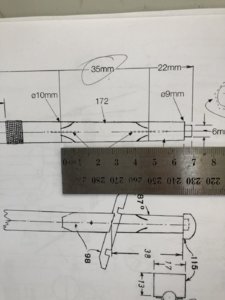
Note in the above, that the scale is 1:1, therefore the square piece should be 35 mm. The scale ruler shows the actual measurement is 47mm. The indicated cut length of 35mm is therefore WRONG. The kit does not provide much spare material for masts and fittings. If you get this cut wrong, you have no spare to account for the error!! As it happens, the Foremast squared material (which uses the SAME timber), has a 35mm length requirement, so I am assuming this is where the error has come from when marking up the Plans.
In general I am very happy with the Billing Boat kit of the Vasa, but this type of mistake in their instructions makes it very difficult and frustrating. It also demands that you 'measure twice and cut once (and ponder the consequences if wrong)".
Regards,
Peter G.
I have also been reviewing the Billing instructions. While in general these are quite good, there is a lot which is not intuitive and where deductions have to be made. There are a number of straight out ERRORS too which is really frustrating. For example, a lot of the masts and spars in the Billing Plans are 1:1 scale. This is great as it allows you to check your lengths of dowling/masts before cutting BUT:
1. The lower lengths of mast sections DO NOT include the parts of the mast which lie below deck. This has to be added to the section lengths shown.
2. Because the above is the case, in some instances the material supplied is barely enough, and in one case, NOT ENOUGH material is supplied.
3. In the photograph below, is a picture of the Billing Plans, for the lower mainmast. Billing construct their masts with their 'square' portion as being a section of square timber material (Part No. 172, in this case), inserted between two round mast sections. A centrally drilled hole at either end with inserted brasswire is then used to secure the three pieces together. In the picture below, note that the squared section is to be 35 mm long.

Note in the above, that the scale is 1:1, therefore the square piece should be 35 mm. The scale ruler shows the actual measurement is 47mm. The indicated cut length of 35mm is therefore WRONG. The kit does not provide much spare material for masts and fittings. If you get this cut wrong, you have no spare to account for the error!! As it happens, the Foremast squared material (which uses the SAME timber), has a 35mm length requirement, so I am assuming this is where the error has come from when marking up the Plans.
In general I am very happy with the Billing Boat kit of the Vasa, but this type of mistake in their instructions makes it very difficult and frustrating. It also demands that you 'measure twice and cut once (and ponder the consequences if wrong)".
Regards,
Peter G.
Hi Peter,Many thanks Snowy (hello to Darwin...).
Maarten, thanks for visiting the build log!! Regarding your offer of photos, I am looking at masts, tops, rigging. In particular, I need photos of the detail of the rigging of upper deadeyes and rigging where they attach to mid-mast (i.e. above the lower mainmast, foremast and mizzen). I am also after detail of the iron wrappings of the mainmast to show where the bands start and finish.
Finally, I don't have any decking detail of the lookout for the helmsman. My understanding is that the helmsman's location was just below decks at the back of the weather deck, but, how did he see out, how were instructions relayed to him from the Master etc etc.?
Any help gratefully accepted. As you know, I am aiming to be detailed and add as much authenticity as I can. Photographs are probably the best method of doing this (other than visiting). I would REALLY love to get my hands on a copy of Vasa II, but it still hasn't been published, I understand. This publication, when released, should have a lot of the detail I am looking for and especially the rigging which is ahead of me.
Regards,
Peter G.
At the moment I am travelling but will have a look at my pictures to see if I have details on these and come back to you.
Many thanks Maarten. I look forward to your getting back to me. Happy travels...
Within the Billing Boat kits, there are the required blocks for the rigging. In preparation for doing the rigging, I thought I would check these, especially as I have seen a number of builders purchase third-party blocks to improve the rigging appearance on their models. In the kit there are:
- 180 Single block 5mm
- 20 Double block 5mm
- 14 Single block 7mm
- 13 Double block 7mm
Total of 227 blocks.
In addition, there are some blocks which are like 'heart' blocks or multiple strand blocks which are laser cut plywood. The total 227 blocks are in a 'kit'-typical, quite hard, fine-grained timber which is light in colour (a straw, or off-yellow). I am unsure what the timber is, but it sands well and can be shaped without splintering or splitting. It does not however take a stain well, presumably due to its density. When I tried to stain a sample of blocks with a quite dark, mahogany brown stain, it changes from the straw colour, to a blotchy brown. Its as if the timber is not absorbing the stain into the grain.
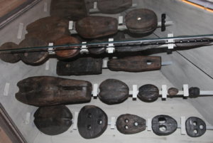
The problem I could most greatly see however is the block shape. Although pre-drilled and with grooves on the outside for tying a support or securing line, the 'corners' of the blocks were almost square, or rounded-square so each block is almost rectangular in shape. Real ship blocks are not square/rectangular. Below is a photo I took in 2017 in Vasamuseet, of some of the displayed block pulleys and deadeyes. As is typical, the blocks are rounded, some almost elliptical, and others egg-shaped, depending on where on the ship they were used. In any case, they definately did not have squared corners. They were also a relatively dark brown in colour (probably of oak timber).
So, I had a choice - I could go and purchase a LOT of blocks made commercially (and there are a number of outlets that can provide these), but it was going to be expensive OR I could try and modify the blocks I had, to better simulate real blocks. I had nothing to lose in modifying them. If it didn't work, I could always go and spend more money and purchase commercial blocks.
I started by mounting my Dremel in its stand and mounting a 1 cm grinding wheel. By holding a block in a non-release (opposite acting) set of tweezers, I could bring the block corners onto the Dremel wheel, smooth the corner by eye and then rotate to the next corner. Obviously, as I ground down the corners until rounded, I also ground away the 'grooves' that were in the original block for rope-tying. So, after rounding the corners, each block had to have the grooves re-created to allow the ropes to be located around the body of the block. This could only be done manually and it was slow and painful work with fingers not happy after the first few, on objects so small. After a long time however, I did manage to get a reasonable compromise. The photo below shows a range of the modified blocks with the original along the bottom row and the altered blocks along the top.
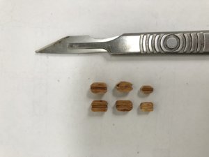
The end result is not too bad for shape. I am not however happy with the colouring. The above is after staining of both before and after re-shaped blocks, and while it is OK, I think a darker brown may be better. You can also see the 'blotchy' appearance. I will experiment with some additional brown washes/paint to trial a better colour.
Time elapsed: 1425 hours
Best Regards,
Peter G.
Within the Billing Boat kits, there are the required blocks for the rigging. In preparation for doing the rigging, I thought I would check these, especially as I have seen a number of builders purchase third-party blocks to improve the rigging appearance on their models. In the kit there are:
- 180 Single block 5mm
- 20 Double block 5mm
- 14 Single block 7mm
- 13 Double block 7mm
Total of 227 blocks.
In addition, there are some blocks which are like 'heart' blocks or multiple strand blocks which are laser cut plywood. The total 227 blocks are in a 'kit'-typical, quite hard, fine-grained timber which is light in colour (a straw, or off-yellow). I am unsure what the timber is, but it sands well and can be shaped without splintering or splitting. It does not however take a stain well, presumably due to its density. When I tried to stain a sample of blocks with a quite dark, mahogany brown stain, it changes from the straw colour, to a blotchy brown. Its as if the timber is not absorbing the stain into the grain.
The problem I could most greatly see however is the block shape. Although pre-drilled and with grooves on the outside for tying a support or securing line, the 'corners' of the blocks were almost square, or rounded-square so each block is almost rectangular in shape. Real ship blocks are not square/rectangular. Below is a photo I took in 2017 in Vasamuseet, of some of the displayed block pulleys and deadeyes. As is typical, the blocks are rounded, some almost elliptical, and others egg-shaped, depending on where on the ship they were used. In any case, they definately did not have squared corners. They were also a relatively dark brown in colour (probably of oak timber).

So, I had a choice - I could go and purchase a LOT of blocks made commercially (and there are a number of outlets that can provide these), but it was going to be expensive OR I could try and modify the blocks I had, to better simulate real blocks. I had nothing to lose in modifying them. If it didn't work, I could always go and spend more money and purchase commercial blocks.
I started by mounting my Dremel in its stand and mounting a 1 cm grinding wheel. By holding a block in a non-release (opposite acting) set of tweezers, I could bring the block corners onto the Dremel wheel, smooth the corner by eye and then rotate to the next corner. Obviously, as I ground down the corners until rounded, I also ground away the 'grooves' that were in the original block for rope-tying. So, after rounding the corners, each block had to have the grooves re-created to allow the ropes to be located around the body of the block. This could only be done manually and it was slow and painful work with fingers not happy after the first few, on objects so small. After a long time however, I did manage to get a reasonable compromise. The photo below shows a range of the modified blocks with the original along the bottom row and the altered blocks along the top.

The end result is not too bad for shape. I am not however happy with the colouring. The above is after staining of both before and after re-shaped blocks, and while it is OK, I think a darker brown may be better. You can also see the 'blotchy' appearance. I will experiment with some additional brown washes/paint to trial a better colour.
Time elapsed: 1425 hours
Best Regards,
Peter G.
Last edited:
At least you got wood blocks, I am building Billing Boats Esmeralda and the blocks are plastic! Nice job on the wood blocks.
Rick
Rick
- Joined
- Dec 3, 2018
- Messages
- 2,451
- Points
- 538

Rick, you should consider replacing the plastic blocks, I built the Cutty Sark of billing, but the whole project stopped completely when the rig started, all the blocks broke when I started tightening the ropes, later I will resurface this model with wood blocks.
Sorry for breaking into this log
Peter G.
Greeting -
.
Sorry for breaking into this log
Peter G.
Greeting -
.
Many thanks Maarten. I look forward to your getting back to me. Happy travels...
Within the Billing Boat kits, there are the required blocks for the rigging. In preparation for doing the rigging, I thought I would check these, especially as I have seen a number of builders purchase third-party blocks to improve the rigging appearance on their models. In the kit there are:
- 180 Single block 5mm
- 20 Double block 5mm
- 14 Single block 7mm
- 13 Double block 7mm
Total of 227 blocks.
In addition, there are some blocks which are like 'heart' blocks or multiple strand blocks which are laser cut plywood. The total 227 blocks are in a 'kit'-typical, quite hard, fine-grained timber which is light in colour (a straw, or off-yellow). I am unsure what the timber is, but it sands well and can be shaped without splintering or splitting. It does not however take a stain well, presumably due to its density. When I tried to stain a sample of blocks with a quite dark, mahogany brown stain, it changes from the straw colour, to a blotchy brown. Its as if the timber is not absorbing the stain into the grain.
The problem I could most greatly see however is the block shape. Although pre-drilled and with grooves on the outside for tying a support or securing line, the 'corners' of the blocks were almost square, or rounded-square so each block is almost rectangular in shape. Real ship blocks are not square/rectangular. Below is a photo I took in 2017 in Vasamuseet, of some of the displayed block pulleys and deadeyes. As is typical, the blocks are rounded, some almost elliptical, and others egg-shaped, depending on where on the ship they were used. In any case, they definately did not have squared corners. They were also a relatively dark brown in colour (probably of oak timber).
View attachment 117919
So, I had a choice - I could go and purchase a LOT of blocks made commercially (and there are a number of outlets that can provide these), but it was going to be expensive OR I could try and modify the blocks I had, to better simulate real blocks. I had nothing to lose in modifying them. If it didn't work, I could always go and spend more money and purchase commercial blocks.
I started by mounting my Dremel in its stand and mounting a 1 cm grinding wheel. By holding a block in a non-release (opposite acting) set of tweezers, I could bring the block corners onto the Dremel wheel, smooth the corner by eye and then rotate to the next corner. Obviously, as I ground down the corners until rounded, I also ground away the 'grooves' that were in the original block for rope-tying. So, after rounding the corners, each block had to have the grooves re-created to allow the ropes to be located around the body of the block. This could only be done manually and it was slow and painful work with fingers not happy after the first few, on objects so small. After a long time however, I did manage to get a reasonable compromise. The photo below shows a range of the modified blocks with the original along the bottom row and the altered blocks along the top.
View attachment 117920
The end result is not too bad for shape. I am not however happy with the colouring. The above is after staining of both before and after re-shaped blocks, and while it is OK, I think a darker brown may be better. You can also see the 'blotchy' appearance. I will experiment with some additional brown washes/paint to trial a better colour.
Time elapsed: 1425 hours
Best Regards,
Peter G.Hi Peter
I used a wood weathering liquid from mico mark to color my Black Pearl build and it worked great. They also carry a dark brown weathering liquid too that might work with your blocks.
Dave
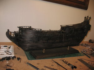
I used a product from Micro Mark to color my Black Peral build. It is a liquid weathering product. I used black but there is also a brown color too. It may be just what you need. The more you use it after it dries the darker it becomes.Many thanks Maarten. I look forward to your getting back to me. Happy travels...
Within the Billing Boat kits, there are the required blocks for the rigging. In preparation for doing the rigging, I thought I would check these, especially as I have seen a number of builders purchase third-party blocks to improve the rigging appearance on their models. In the kit there are:
- 180 Single block 5mm
- 20 Double block 5mm
- 14 Single block 7mm
- 13 Double block 7mm
Total of 227 blocks.
In addition, there are some blocks which are like 'heart' blocks or multiple strand blocks which are laser cut plywood. The total 227 blocks are in a 'kit'-typical, quite hard, fine-grained timber which is light in colour (a straw, or off-yellow). I am unsure what the timber is, but it sands well and can be shaped without splintering or splitting. It does not however take a stain well, presumably due to its density. When I tried to stain a sample of blocks with a quite dark, mahogany brown stain, it changes from the straw colour, to a blotchy brown. Its as if the timber is not absorbing the stain into the grain.
The problem I could most greatly see however is the block shape. Although pre-drilled and with grooves on the outside for tying a support or securing line, the 'corners' of the blocks were almost square, or rounded-square so each block is almost rectangular in shape. Real ship blocks are not square/rectangular. Below is a photo I took in 2017 in Vasamuseet, of some of the displayed block pulleys and deadeyes. As is typical, the blocks are rounded, some almost elliptical, and others egg-shaped, depending on where on the ship they were used. In any case, they definately did not have squared corners. They were also a relatively dark brown in colour (probably of oak timber).
View attachment 117919
So, I had a choice - I could go and purchase a LOT of blocks made commercially (and there are a number of outlets that can provide these), but it was going to be expensive OR I could try and modify the blocks I had, to better simulate real blocks. I had nothing to lose in modifying them. If it didn't work, I could always go and spend more money and purchase commercial blocks.
I started by mounting my Dremel in its stand and mounting a 1 cm grinding wheel. By holding a block in a non-release (opposite acting) set of tweezers, I could bring the block corners onto the Dremel wheel, smooth the corner by eye and then rotate to the next corner. Obviously, as I ground down the corners until rounded, I also ground away the 'grooves' that were in the original block for rope-tying. So, after rounding the corners, each block had to have the grooves re-created to allow the ropes to be located around the body of the block. This could only be done manually and it was slow and painful work with fingers not happy after the first few, on objects so small. After a long time however, I did manage to get a reasonable compromise. The photo below shows a range of the modified blocks with the original along the bottom row and the altered blocks along the top.
View attachment 117920
The end result is not too bad for shape. I am not however happy with the colouring. The above is after staining of both before and after re-shaped blocks, and while it is OK, I think a darker brown may be better. You can also see the 'blotchy' appearance. I will experiment with some additional brown washes/paint to trial a better colour.
Time elapsed: 1425 hours
Best Regards,
Peter G.
Dave
Thanks Dave. I'll look into that product. I tend to be using Vallejo paints which I can obtain easily, but they are not as good on wood as plastic. If the brand was MicoLux, Model Shipways or Badger, I don't know of an outlet in Australia. We can get stuff sent out from the US, but it's a pain and takes a while. Which brand were you using?
Knut (Norway), I remember building the Billing Cutty Sark and grappling with the plastic blocks. It was not a fun experience. I am surprised that Billings persist with including these when the wooden blocks these days can be of such high quality and not overly expensive. I guess it is a cost issue. I am far enough down the 'modified' blocks of the Vasa Billing kit that I will persist with them. At this stage I think they will look OK, and with the painting as Dave has suggested, should look quite alright.
Regards,
Peter G.
Next item on the agenda, the tops.
The tops as provided in the Billing Boats kit come in three sizes - large for mainmast lower, medium for foremast lower and four identical small tops for higher main, fore and mizzen locations. These are provided as plywood laser cutouts including a series of 'rings' which are layered one on top of another to build the required height and with increasing diameters to give the size increase with height. The uppermost, half rings are particularly thin and narrow and subject to breaking if mishandled.
I found that when I stacked the required three rings plywood rings onto the plywood base, the elevated height and resulting thickness was just too high and not in scale. If I dropped out the second ring (the same internal diameter as the third ring), and then sanded one plywood layer off (to result in two ply layers), the thickness and appearance was about right. I was also not happy with the appearance of the plywood timber on the base of the top, as it was not planked, as is the case on the real ship. A replica of the 'real' ship tops in Vasamuseet is shown below and you can actually walk on this and examine the way the tops were built (see below).
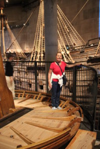
The tops planking can clearly be seen on the base as well as the various staves/timber supports which radiate out from the inner base surface to support the elevated sides. In total, there are 16 of these, but in the BB kit, only a maximum of 12 were provided. The other thing about these radiating supports is that they are provided from the laser-cut plywood, so when cut out and sanded, their edges (which are uppermost), show the layering of the plywood, which I wasn't happy about.
To address the issues above, for each of the tops, I did the following:
1. I sanded each plywood base and ring significantly to reduce their thicknesses by about half (a lot of work).
2. I used the various sized internal support supports as templates and created my own with sharp knife and Dremel to shape the curved upper surfaces. I did this with mahogany planking which was about the correct thickness, but had to be shaped. I had to be selective about the grain of the plank to ensure the support did not crack or chip.
3. I increased the number of internal top supports to 16 on the mid and large tops and to 8 for the small tops.
4. For each increasing height ring of plywood, I sanded to half thickness to scale the overall tops thickness/height.
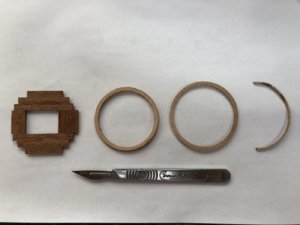
Layering the top base was simple with planking glued to a thinned plywood circular shape. Once glued onto the base, the uneven, planked edge was cut and sanded to match the laser-cut plywood sized base. The photo below shows a small top. Four of these in total is required.
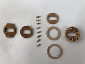
Below is a picture of the basic components of one of the large sized tops. This shows the planked surface of the plywood base before sanding to round and fitting the tops rings.
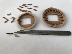
The next photo shows examples of tops in the process of being completed with a completed main top on the right. The various crafted internal supports of the top on the left are shown to increase the number to 16.
With the tops completed, I am about to move on to the masts and spars.
Time elapsed: 1460 hours
Regards,
Peter G.
The tops as provided in the Billing Boats kit come in three sizes - large for mainmast lower, medium for foremast lower and four identical small tops for higher main, fore and mizzen locations. These are provided as plywood laser cutouts including a series of 'rings' which are layered one on top of another to build the required height and with increasing diameters to give the size increase with height. The uppermost, half rings are particularly thin and narrow and subject to breaking if mishandled.
I found that when I stacked the required three rings plywood rings onto the plywood base, the elevated height and resulting thickness was just too high and not in scale. If I dropped out the second ring (the same internal diameter as the third ring), and then sanded one plywood layer off (to result in two ply layers), the thickness and appearance was about right. I was also not happy with the appearance of the plywood timber on the base of the top, as it was not planked, as is the case on the real ship. A replica of the 'real' ship tops in Vasamuseet is shown below and you can actually walk on this and examine the way the tops were built (see below).

The tops planking can clearly be seen on the base as well as the various staves/timber supports which radiate out from the inner base surface to support the elevated sides. In total, there are 16 of these, but in the BB kit, only a maximum of 12 were provided. The other thing about these radiating supports is that they are provided from the laser-cut plywood, so when cut out and sanded, their edges (which are uppermost), show the layering of the plywood, which I wasn't happy about.
To address the issues above, for each of the tops, I did the following:
1. I sanded each plywood base and ring significantly to reduce their thicknesses by about half (a lot of work).
2. I used the various sized internal support supports as templates and created my own with sharp knife and Dremel to shape the curved upper surfaces. I did this with mahogany planking which was about the correct thickness, but had to be shaped. I had to be selective about the grain of the plank to ensure the support did not crack or chip.
3. I increased the number of internal top supports to 16 on the mid and large tops and to 8 for the small tops.
4. For each increasing height ring of plywood, I sanded to half thickness to scale the overall tops thickness/height.
Layering the top base was simple with planking glued to a thinned plywood circular shape. Once glued onto the base, the uneven, planked edge was cut and sanded to match the laser-cut plywood sized base. The photo below shows a small top. Four of these in total is required.

Below is a picture of the basic components of one of the large sized tops. This shows the planked surface of the plywood base before sanding to round and fitting the tops rings.

The next photo shows examples of tops in the process of being completed with a completed main top on the right. The various crafted internal supports of the top on the left are shown to increase the number to 16.

With the tops completed, I am about to move on to the masts and spars.
Time elapsed: 1460 hours
Regards,
Peter G.
Hi Peter, back in the office so looked through pictures I have on file.Many thanks Snowy (hello to Darwin...).
Maarten, thanks for visiting the build log!! Regarding your offer of photos, I am looking at masts, tops, rigging. In particular, I need photos of the detail of the rigging of upper deadeyes and rigging where they attach to mid-mast (i.e. above the lower mainmast, foremast and mizzen). I am also after detail of the iron wrappings of the mainmast to show where the bands start and finish.
Finally, I don't have any decking detail of the lookout for the helmsman. My understanding is that the helmsman's location was just below decks at the back of the weather deck, but, how did he see out, how were instructions relayed to him from the Master etc etc.?
Any help gratefully accepted. As you know, I am aiming to be detailed and add as much authenticity as I can. Photographs are probably the best method of doing this (other than visiting). I would REALLY love to get my hands on a copy of Vasa II, but it still hasn't been published, I understand. This publication, when released, should have a lot of the detail I am looking for and especially the rigging which is ahead of me.
Regards,
Peter G.
First the lookout for the helmsman. He was situated before the great cabin in the staircase. There is an opening in the bullwark the look onto the deck. You can clearly see this on the halfmodel in the museum.
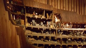
And you can walk through a mockup of this area.
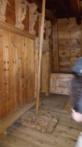
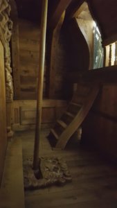
And the outside situation, the helmsman is looking through the area between the lower carvings between the two doors.
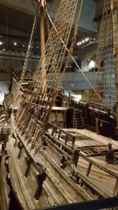
On the rigging there is not much to see on the original ship as only the lower masts are remaining.
There are no steel bands arounds the main mast, these are rope bands (Woelingen in Dutch)
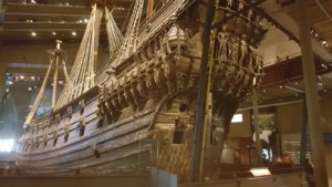
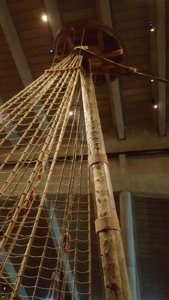
Great photos of the great ship!
Maarten,
Many, many thanks for these great photographs. I was not aware that there was a 'mock-up' walk through of the helmsman's loft of the ship. It also gives an idea of the movement available from the tiller linkage and its LONG run back to the actual rudder in the stern. The long arm of the tiller is hard to see in the cutaway model, but I know it is there. This will enable me to accurately model that part of the ship with the viewing ports available to the helmsman between the figures in the deck break.
As regards the upper rigging complexities, what you have provided will assist but what I am really looking for is information about the run of halyards for the midsection and topmast uphaul for the spars. In the BB kit, this is simply a hole, drilled into the midsection and topmast timber. I suspect however that it actually would have been a suspended block or pulley through the mast. As you say, this is not provided at Vasamuseet. As an example, I show below the instructions for part of the mainmast where I have shown in red circles, where the instructions imply that you have to feed the spar halyard uphauls through a hole drilled in the mast.
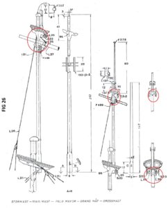
What your photo shows really well however is the lamination of the timbers for the mainmast, which I do not have, so this is really useful. Again, May thanks, Maarten.
Best Regards,
Peter G.
Many, many thanks for these great photographs. I was not aware that there was a 'mock-up' walk through of the helmsman's loft of the ship. It also gives an idea of the movement available from the tiller linkage and its LONG run back to the actual rudder in the stern. The long arm of the tiller is hard to see in the cutaway model, but I know it is there. This will enable me to accurately model that part of the ship with the viewing ports available to the helmsman between the figures in the deck break.
As regards the upper rigging complexities, what you have provided will assist but what I am really looking for is information about the run of halyards for the midsection and topmast uphaul for the spars. In the BB kit, this is simply a hole, drilled into the midsection and topmast timber. I suspect however that it actually would have been a suspended block or pulley through the mast. As you say, this is not provided at Vasamuseet. As an example, I show below the instructions for part of the mainmast where I have shown in red circles, where the instructions imply that you have to feed the spar halyard uphauls through a hole drilled in the mast.

What your photo shows really well however is the lamination of the timbers for the mainmast, which I do not have, so this is really useful. Again, May thanks, Maarten.
Best Regards,
Peter G.
Thanks Dave. I'll look into that product. I tend to be using Vallejo paints which I can obtain easily, but they are not as good on wood as plastic. If the brand was MicoLux, Model Shipways or Badger, I don't know of an outlet in Australia. We can get stuff sent out from the US, but it's a pain and takes a while. Which brand were you using?
Knut (Norway), I remember building the Billing Cutty Sark and grappling with the plastic blocks. It was not a fun experience. I am surprised that Billings persist with including these when the wooden blocks these days can be of such high quality and not overly expensive. I guess it is a cost issue. I am far enough down the 'modified' blocks of the Vasa Billing kit that I will persist with them. At this stage I think they will look OK, and with the painting as Dave has suggested, should look quite alright.
Regards,
Peter G.Here are some pictures of the product and the result I had.
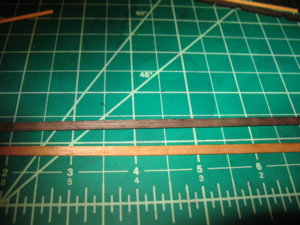

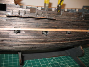
Wow, that looks really effective.
What is the original wood?
Regards,
Peter G.
What is the original wood?
Regards,
Peter G.
Hi David.
Your Black Pearl is outstanding. It really looks like a pirate ship!! Clearly the stain/paint you are using works well. Interesting that Micro-Mark call this colour 'Grey'. Also it is in a container of only 3.5 Fluid Oz, so a little goes a long way.
Regards,
Peter G.
Your Black Pearl is outstanding. It really looks like a pirate ship!! Clearly the stain/paint you are using works well. Interesting that Micro-Mark call this colour 'Grey'. Also it is in a container of only 3.5 Fluid Oz, so a little goes a long way.
Regards,
Peter G.


