-

Win a Free Custom Engraved Brass Coin!!!
As a way to introduce our brass coins to the community, we will raffle off a free coin during the month of August. Follow link ABOVE for instructions for entering.
-

PRE-ORDER SHIPS IN SCALE TODAY!
The beloved Ships in Scale Magazine is back and charting a new course for 2026!
Discover new skills, new techniques, and new inspirations in every issue.
NOTE THAT OUR FIRST ISSUE WILL BE JAN/FEB 2026
You are using an out of date browser. It may not display this or other websites correctly.
You should upgrade or use an alternative browser.
You should upgrade or use an alternative browser.
Vasa Build Log - Billing Boats - Scale 1/75 [COMPLETED BUILD]
I'm excited!!! Came across a breakthrough website today. A little of the background.....
A few posts ago, Maarten sent me some photographs of the Helmsman's cabin/loft forehead of the Great Cabin. This was excellent for showing me the 'slits' through which the helmsman received orders and could see to steer the ship. I was however a little curious as to what the helmsman would actually see, so I did a Google search on the topic and came across the most awesome website describing the work being done by Håkan Thorén who has been working for the Vasa museum in Stockholm for about two years. Håkan is an archaeologist but has recently been working on technical applications in archaeology like GIS, software development, total station surveying and laser scanning.
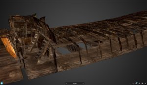
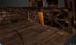
In particular, Håkan has been working on a 3D Management Tool to provide a framework for 3D image rendering of the Vasa. His website describes the process, the cameras, images and their 3D GIS location such that for the main Gun Deck (the first level below the Main Deck), he provides a 3D interactive environment using SketchPad. For me, the Helmsman's Loft is totally visible and in VERY high detail. Below I show two pictures captured off the computer screen from the 3D SketchPad application. The first photo shows the Helmsman's Loft (to the left) with the Main Deck and Gun Deck stretching to the right. The second photo, I have rotated the view and zoomed in to show part of the Main Cabin and the location where the Mizzen Mast as it comes through the raised Weather Deck.
The website to access this is located at:
 sketchfab.com
This development is a part of a Swedish National Maritime Museum's project. On the website are some images, but also the link to take you to the 3D rendering Sketchpad application for computer, smartphone or tablet. At present only the Gun Deck has been made available in 3D, but this shows the incredibly powerful scope of detail, navigation and views of the actual ship that can be obtained. In the future, the whole ship is intended to be made available. Within the 3D view too are isolated 'marker's that provide information and can be clicked on to take you to an optimal view, from stern to beak. As Håkan says, for the future:
"The management tool is at the moment under development and is planned to be tested and ready for use in the near future. The completion of the (entire ship) 3D model will take a little bit longer. According to plan we will have a complete model of Vasa by the end of 2021 and we plan to continuously upload all parts to Sketchfab."
I think this development could revolutionize the detail that could be made available in a ship such as the Vasa. This work is invaluable in providing those views and information so important to our modelling community. Another development underway, is to use the Management Tool to permit access to 3D views of artefacts recovered from the ship. As there are over 20,000 of these, it would be a massive job, but even to get on board a 'virtual Vasa' would be of immense assistance to modellers all over the world.
I hope you find this as interesting as I have,
Regards,
Peter G.
A few posts ago, Maarten sent me some photographs of the Helmsman's cabin/loft forehead of the Great Cabin. This was excellent for showing me the 'slits' through which the helmsman received orders and could see to steer the ship. I was however a little curious as to what the helmsman would actually see, so I did a Google search on the topic and came across the most awesome website describing the work being done by Håkan Thorén who has been working for the Vasa museum in Stockholm for about two years. Håkan is an archaeologist but has recently been working on technical applications in archaeology like GIS, software development, total station surveying and laser scanning.
In particular, Håkan has been working on a 3D Management Tool to provide a framework for 3D image rendering of the Vasa. His website describes the process, the cameras, images and their 3D GIS location such that for the main Gun Deck (the first level below the Main Deck), he provides a 3D interactive environment using SketchPad. For me, the Helmsman's Loft is totally visible and in VERY high detail. Below I show two pictures captured off the computer screen from the 3D SketchPad application. The first photo shows the Helmsman's Loft (to the left) with the Main Deck and Gun Deck stretching to the right. The second photo, I have rotated the view and zoomed in to show part of the Main Cabin and the location where the Mizzen Mast as it comes through the raised Weather Deck.


The website to access this is located at:

Digitizing a Preserved 17th Century Ship
Håkan Thorén of the Vasa Museum in Stockholm tells us about the arduous process involved in digitizing the only extant 17th century ship in the world.
This development is a part of a Swedish National Maritime Museum's project. On the website are some images, but also the link to take you to the 3D rendering Sketchpad application for computer, smartphone or tablet. At present only the Gun Deck has been made available in 3D, but this shows the incredibly powerful scope of detail, navigation and views of the actual ship that can be obtained. In the future, the whole ship is intended to be made available. Within the 3D view too are isolated 'marker's that provide information and can be clicked on to take you to an optimal view, from stern to beak. As Håkan says, for the future:
"The management tool is at the moment under development and is planned to be tested and ready for use in the near future. The completion of the (entire ship) 3D model will take a little bit longer. According to plan we will have a complete model of Vasa by the end of 2021 and we plan to continuously upload all parts to Sketchfab."
I think this development could revolutionize the detail that could be made available in a ship such as the Vasa. This work is invaluable in providing those views and information so important to our modelling community. Another development underway, is to use the Management Tool to permit access to 3D views of artefacts recovered from the ship. As there are over 20,000 of these, it would be a massive job, but even to get on board a 'virtual Vasa' would be of immense assistance to modellers all over the world.
I hope you find this as interesting as I have,
Regards,
Peter G.
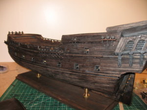
Thanks David. Really impressive detail on your Black Pearl. Clearly that stain is doing an excellent job, but the fine detail and attention to the small items you include, especially on deck, will make this an exceptional model. Congratulations.
Although the Black Pearl is a fictional ship (from the Pirates of the Caribbean film series), the ship is easily recognized by her distinctive black hull and sails and I can almost imagine Captain Jack Sparrow emerging from below or standing on deck.... Any ideas of including some of the figures?
Regards,
Peter G.
I am commencing work on the spars, masts and bowsprit etc. With the tops finished, this is the next logical stage. I thought I would start with the bowsprit and the steps to be followed are:
1. Identify the timber (quite an exercise as there are a number of diameters, lengths and timber types for the 3 masts, mast sections and spars plus bowsprit).
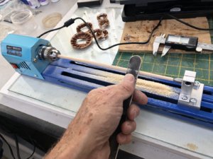
2. Take the bowsprit timber and shape it to have a taper as instructed. I used a small lathe I have to do this. It was cheap and I have transferred the motor drive to a much longer slide to allow the mast lengths to be sanded. I can set the centre points of the wood and lock it between the slide points and then sand it accurately. The lathe is shown below.
3. With the bowsprit tapered, I then needed to scribe the sides with the back of a sharp blade (using a technique that follows a straight length of stick-on Dymo tape. The blade follows the tape shape and allows the hull entry end of the spar to have four scribe marks along its length that then come together. The area scribed was then stained to indicate a different wood used as if the bowsprit were 'laminated' from different timbers as on the real ship.
4. Once the staining and bowsprit timber was finished, I then wrapped white glue impregnated, thin black paper around it near its base from about 1/3 along, to simulate the iron banding on the original ship.
5. Cut out the laser-cut plywood 'knee' at the front of the bowsprit and attach. This was to then have crosstrees fitted and one of the small tops.
6. Above the tops the spritsail mast sections are added. Below is a photo of the developing bowsprit. The next items will include staining the mast sections plus the addition of deadeyes and blocks. I am keen to get as much added to the masts/bowsprit as possible before actually attaching to the ship. I have ensured that the masts etc fit appropriately in the ship and when this is done, it should be a relatively easy job.
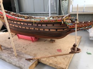
Elapsed Time: 1470 Hours
Regards,
Peter G.
1. Identify the timber (quite an exercise as there are a number of diameters, lengths and timber types for the 3 masts, mast sections and spars plus bowsprit).
2. Take the bowsprit timber and shape it to have a taper as instructed. I used a small lathe I have to do this. It was cheap and I have transferred the motor drive to a much longer slide to allow the mast lengths to be sanded. I can set the centre points of the wood and lock it between the slide points and then sand it accurately. The lathe is shown below.

3. With the bowsprit tapered, I then needed to scribe the sides with the back of a sharp blade (using a technique that follows a straight length of stick-on Dymo tape. The blade follows the tape shape and allows the hull entry end of the spar to have four scribe marks along its length that then come together. The area scribed was then stained to indicate a different wood used as if the bowsprit were 'laminated' from different timbers as on the real ship.
4. Once the staining and bowsprit timber was finished, I then wrapped white glue impregnated, thin black paper around it near its base from about 1/3 along, to simulate the iron banding on the original ship.
5. Cut out the laser-cut plywood 'knee' at the front of the bowsprit and attach. This was to then have crosstrees fitted and one of the small tops.
6. Above the tops the spritsail mast sections are added. Below is a photo of the developing bowsprit. The next items will include staining the mast sections plus the addition of deadeyes and blocks. I am keen to get as much added to the masts/bowsprit as possible before actually attaching to the ship. I have ensured that the masts etc fit appropriately in the ship and when this is done, it should be a relatively easy job.

Elapsed Time: 1470 Hours
Regards,
Peter G.
Beautiful work I can't wait for the masting and rigging.
This is a great link - many thanks for sharing with usI'm excited!!! Came across a breakthrough website today. A little of the background.....
A few posts ago, Maarten sent me some photographs of the Helmsman's cabin/loft forehead of the Great Cabin. This was excellent for showing me the 'slits' through which the helmsman received orders and could see to steer the ship. I was however a little curious as to what the helmsman would actually see, so I did a Google search on the topic and came across the most awesome website describing the work being done by Håkan Thorén who has been working for the Vasa museum in Stockholm for about two years. Håkan is an archaeologist but has recently been working on technical applications in archaeology like GIS, software development, total station surveying and laser scanning.
In particular, Håkan has been working on a 3D Management Tool to provide a framework for 3D image rendering of the Vasa. His website describes the process, the cameras, images and their 3D GIS location such that for the main Gun Deck (the first level below the Main Deck), he provides a 3D interactive environment using SketchPad. For me, the Helmsman's Loft is totally visible and in VERY high detail. Below I show two pictures captured off the computer screen from the 3D SketchPad application. The first photo shows the Helmsman's Loft (to the left) with the Main Deck and Gun Deck stretching to the right. The second photo, I have rotated the view and zoomed in to show part of the Main Cabin and the location where the Mizzen Mast as it comes through the raised Weather Deck.
View attachment 119527
View attachment 119528
The website to access this is located at:

Digitizing a Preserved 17th Century Ship
Håkan Thorén of the Vasa Museum in Stockholm tells us about the arduous process involved in digitizing the only extant 17th century ship in the world.sketchfab.com
This development is a part of a Swedish National Maritime Museum's project. On the website are some images, but also the link to take you to the 3D rendering Sketchpad application for computer, smartphone or tablet. At present only the Gun Deck has been made available in 3D, but this shows the incredibly powerful scope of detail, navigation and views of the actual ship that can be obtained. In the future, the whole ship is intended to be made available. Within the 3D view too are isolated 'marker's that provide information and can be clicked on to take you to an optimal view, from stern to beak. As Håkan says, for the future:
"The management tool is at the moment under development and is planned to be tested and ready for use in the near future. The completion of the (entire ship) 3D model will take a little bit longer. According to plan we will have a complete model of Vasa by the end of 2021 and we plan to continuously upload all parts to Sketchfab."
I think this development could revolutionize the detail that could be made available in a ship such as the Vasa. This work is invaluable in providing those views and information so important to our modelling community. Another development underway, is to use the Management Tool to permit access to 3D views of artefacts recovered from the ship. As there are over 20,000 of these, it would be a massive job, but even to get on board a 'virtual Vasa' would be of immense assistance to modellers all over the world.
I hope you find this as interesting as I have,
Regards,
Peter G.
- Joined
- Aug 16, 2019
- Messages
- 870
- Points
- 343

For me it is a joy to follow your build 

Great site, this should be available for VR so everyone can walk through the Vasa at home.I'm excited!!! Came across a breakthrough website today. A little of the background.....
A few posts ago, Maarten sent me some photographs of the Helmsman's cabin/loft forehead of the Great Cabin. This was excellent for showing me the 'slits' through which the helmsman received orders and could see to steer the ship. I was however a little curious as to what the helmsman would actually see, so I did a Google search on the topic and came across the most awesome website describing the work being done by Håkan Thorén who has been working for the Vasa museum in Stockholm for about two years. Håkan is an archaeologist but has recently been working on technical applications in archaeology like GIS, software development, total station surveying and laser scanning.
In particular, Håkan has been working on a 3D Management Tool to provide a framework for 3D image rendering of the Vasa. His website describes the process, the cameras, images and their 3D GIS location such that for the main Gun Deck (the first level below the Main Deck), he provides a 3D interactive environment using SketchPad. For me, the Helmsman's Loft is totally visible and in VERY high detail. Below I show two pictures captured off the computer screen from the 3D SketchPad application. The first photo shows the Helmsman's Loft (to the left) with the Main Deck and Gun Deck stretching to the right. The second photo, I have rotated the view and zoomed in to show part of the Main Cabin and the location where the Mizzen Mast as it comes through the raised Weather Deck.
View attachment 119527
View attachment 119528
The website to access this is located at:

Digitizing a Preserved 17th Century Ship
Håkan Thorén of the Vasa Museum in Stockholm tells us about the arduous process involved in digitizing the only extant 17th century ship in the world.sketchfab.com
This development is a part of a Swedish National Maritime Museum's project. On the website are some images, but also the link to take you to the 3D rendering Sketchpad application for computer, smartphone or tablet. At present only the Gun Deck has been made available in 3D, but this shows the incredibly powerful scope of detail, navigation and views of the actual ship that can be obtained. In the future, the whole ship is intended to be made available. Within the 3D view too are isolated 'marker's that provide information and can be clicked on to take you to an optimal view, from stern to beak. As Håkan says, for the future:
"The management tool is at the moment under development and is planned to be tested and ready for use in the near future. The completion of the (entire ship) 3D model will take a little bit longer. According to plan we will have a complete model of Vasa by the end of 2021 and we plan to continuously upload all parts to Sketchfab."
I think this development could revolutionize the detail that could be made available in a ship such as the Vasa. This work is invaluable in providing those views and information so important to our modelling community. Another development underway, is to use the Management Tool to permit access to 3D views of artefacts recovered from the ship. As there are over 20,000 of these, it would be a massive job, but even to get on board a 'virtual Vasa' would be of immense assistance to modellers all over the world.
I hope you find this as interesting as I have,
Regards,
Peter G.
Btw, your Vasa is becomming a great model.
Well, your craftmanship, skills, eye for detail and determination to do as best a job as possible in building the Wasa. Gave me the nerve to purchase a kit. It also is a Billing Boats kit, got it for about half the current price, on eBay. Though at the moment I am knee deep in another build, a Billing Boats Esmeralda. It will be awhile before I get to the Wasa, I will continue to follow your build. The best compliment I can give, I will I am sure refer back to this thread many, many times to emulate as best as I can your talents. I was looking at Books f/the Wasa and the Hakan Thoren Book.....$  is more than I paid for the kit! Looking forward to seeing what you do next with this excellent piece of work.
Rick
Rick
Hi Peter,Great site, this should be available for VR so everyone can walk through the Vasa at home.
Btw, your Vasa is becomming a great model.
I looked in depth to this site and it is great. They actually have a VR tool. If you have a VR glass for your mobile phone you can actually walk through hthe Vasa in your own living room as iff you are standing onboard yourselve. As I am travelling abrought at the moment I wil test it tomorrow when I am back at home. This should be great experience.
Many thanks to all those who have responded recently. In particular, David, Charles, Neophyte (Rick) and Maarten.
To Neophyte (Rick) - Its always great when you can get a bargain. Good pickup on EBay!! The Esmeralda is an amazing ship and I remember as a kid, seeing her sailing into Sydney Harbour during an Around-The-World sailing/training voyage. It left a wonderful, lasting impression. I look forward to seeing your build result. You are too kind regarding comments about my build. I just like to have the ship as accurate as I can, and the Billing Boat kits allow the modeller to 'scratch' parts etc such that they can add their own authenticity and detail to the ships they build. I am aware of the costs of some the specialist reference books that are written and produced on subjects such as the Vasa. Since these publications are of limited appeal and not too many will be sold, I guess the high cost of publication has to be returned to make the effort of writing worthwhile.
To Uwe and Maarten - The VR site and tool is excellent and I look forward to additional publication of other parts of the ship. It gives significant detail and the ability to look into locations on the hull, rigging etc which are unique. I especially look forward to a release of the outer hull and especially the galleries of the Vasa.
Best Regards,
Peter G.
I have been figuring out a way to mount and secure the deadeyes to the tops. The bowsprit is the most difficult as the strops continue through the base of the top to be secured into the timber of the bowsprit itself. There are three deadeyes each side and these have to be mounted at the same height above the top level on both port and starboard sides. So, I have read a few ideas as to how different modellers have secured these. Some of the methods involved, using 0.7mm copper wire around the deadeye and then twisting so the twist can be mounted into a drilled hole. This method I did not like as the twist is not authentic, it will be visible, and it is hard to use the twisted wire beneath the top as a strop or be bent to form an eye for ratlines below (in the case of the main, fore and mizzen mast lines).
A second method is to use copper wire to form the same shape as used for the main chainplate deadeyes and then secure below by a line to the top. While this is more elegant and matches what I have already done for the chainplate deadeyes, it is not consistent with forming an eye beneath the tops of the other mast tops.
The third and I think most practical method which I have adopted, is to wrap the deadeye with copper wire, then bend ONE end beneath the deadeye and solder to the other, single strand which is then extended below holes in the tops. These extended wire pieces are then easily bent into a loop, and secured back into the hole to form a loop, eyelet for rigging below the top. Below I show a picture of the three methods, with the extended wire method on the right.
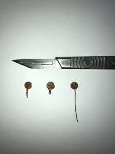
Although I like the above method, It does pose one problem (as applies to ALL the methods) - How do you get the strop blackened? If you blacken it (by painting or by copper blackening solution), then it is difficult to solder (without cleaning the wire parts to be joined). If you solder first, and then dip into copper blackening solution, what effect will it have on the wood of the deadeye?
Well, I tried both methods, solder first and then dip into blackening solution, and blackening first and then clean to solder. The soldering first did indeed make the deadeye dark and with a 'dirty' look, so I was then left with the second method, which was slow and required only the required part of the wire to be cleaned with a scalpel before soldering - but it did work.
OK, now I have my 40 required deadeyes for all the tops with wire strop extensions. In the case of the bowsprit however, the extensions were actually flattened 'bars' which continued down to the timber of the bowsprit and secured, rather than roped extensions. Hang on!! I am dealing with copper wire - Perfect for flattening!! So I simply laid six of the deadeye copper wire extensions onto a metal plate, and hammered them flat. A little black paint and Voila - Flat, metal strop extensions to be secured into the bowsprit timber. Below is the result.
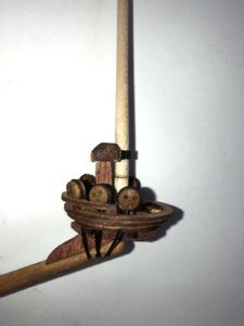
In the above, you can see the painted and flattened copper wire extensions below the top. Note too that I have not stained the spritsail mast section above this top yet, so it appears lighter in colour.
With this top now nearly complete, I turned my attention to the other tops of the mainmast, foremast and mizzen. These tops can have their deadeyes added to the tops even before the masts are finished (so long as you don't glue and finish the various fittings of the masts which prevent the tops fitting over and down the mast sections to the final required location). As an example, in the case of the small mizzenmast top, below is a picture which shows the top, unsecured, but in its correct place. It is unglued but shows the deadeyes with their single wire extension, this time, not flattened, but bent to a loop which is then returned into the base wood of the top to form an eye. These eyes are then used to secure the ratline lines which extend from lower in the mast or ship deck levels.
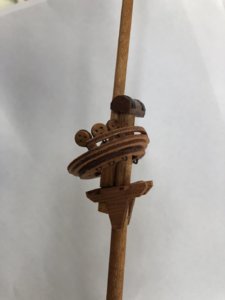
I will continue to complete all the deadeyes for the other tops and then work more on the masts themselves.
Elapsed Time: 1495 Hours
Regards,
Peter G.
A second method is to use copper wire to form the same shape as used for the main chainplate deadeyes and then secure below by a line to the top. While this is more elegant and matches what I have already done for the chainplate deadeyes, it is not consistent with forming an eye beneath the tops of the other mast tops.
The third and I think most practical method which I have adopted, is to wrap the deadeye with copper wire, then bend ONE end beneath the deadeye and solder to the other, single strand which is then extended below holes in the tops. These extended wire pieces are then easily bent into a loop, and secured back into the hole to form a loop, eyelet for rigging below the top. Below I show a picture of the three methods, with the extended wire method on the right.

Although I like the above method, It does pose one problem (as applies to ALL the methods) - How do you get the strop blackened? If you blacken it (by painting or by copper blackening solution), then it is difficult to solder (without cleaning the wire parts to be joined). If you solder first, and then dip into copper blackening solution, what effect will it have on the wood of the deadeye?
Well, I tried both methods, solder first and then dip into blackening solution, and blackening first and then clean to solder. The soldering first did indeed make the deadeye dark and with a 'dirty' look, so I was then left with the second method, which was slow and required only the required part of the wire to be cleaned with a scalpel before soldering - but it did work.
OK, now I have my 40 required deadeyes for all the tops with wire strop extensions. In the case of the bowsprit however, the extensions were actually flattened 'bars' which continued down to the timber of the bowsprit and secured, rather than roped extensions. Hang on!! I am dealing with copper wire - Perfect for flattening!! So I simply laid six of the deadeye copper wire extensions onto a metal plate, and hammered them flat. A little black paint and Voila - Flat, metal strop extensions to be secured into the bowsprit timber. Below is the result.

In the above, you can see the painted and flattened copper wire extensions below the top. Note too that I have not stained the spritsail mast section above this top yet, so it appears lighter in colour.
With this top now nearly complete, I turned my attention to the other tops of the mainmast, foremast and mizzen. These tops can have their deadeyes added to the tops even before the masts are finished (so long as you don't glue and finish the various fittings of the masts which prevent the tops fitting over and down the mast sections to the final required location). As an example, in the case of the small mizzenmast top, below is a picture which shows the top, unsecured, but in its correct place. It is unglued but shows the deadeyes with their single wire extension, this time, not flattened, but bent to a loop which is then returned into the base wood of the top to form an eye. These eyes are then used to secure the ratline lines which extend from lower in the mast or ship deck levels.

I will continue to complete all the deadeyes for the other tops and then work more on the masts themselves.
Elapsed Time: 1495 Hours
Regards,
Peter G.
A question for all those avid Vasa modellers. I am shaping some spars on this Billing Boats kit. Below is an image of part of the instructions for the spars. Note it is saying to shave/file the outer ends of the spars to be a reduced diameter.
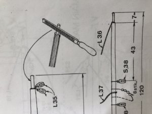
I have examined some other authorities websites (such as Clayton’s model and rigging), and can find no evidence of this reduction of diameter at the ends of the spars. I also cannot see it in the 1/10 scale model at the museum.
Has anybody else seen this spar diameter reduction, or is it a Billing Boats ‘thing’?
Regards,
Peter G.
Many thanks Michael and Maarten. It does appear that these have reduced spar end sizes. When looking at the spars, it just looks odd, but I guess when covered by end ropes and tackle, you don’t notice it anyway.
I might post the question on Fred Hocker’s blog to see what the spars that were brought to the surface reveal. I now think you are correct though, Michael.
Peter G.
I might post the question on Fred Hocker’s blog to see what the spars that were brought to the surface reveal. I now think you are correct though, Michael.
Peter G.
I would like to order this Wasa ship. But I have never built wooden model. My concern is about instructions. At the beginning of this building log you mentioned that instructions are not clear in this model. I concern myself to be capable to do thinks, if i know how to do them, but I am afraid that when somethink is unclear I will not be abble to continue. My question is whether to buy this and figure it out or it is better for me to buy somethink else, maybe more expensive, but with clearer instructions?
HiI would like to order this Wasa ship. But I have never built wooden model. My concern is about instructions. At the beginning of this building log you mentioned that instructions are not clear in this model. I concern myself to be capable to do thinks, if i know how to do them, but I am afraid that when somethink is unclear I will not be abble to continue. My question is whether to buy this and figure it out or it is better for me to buy somethink else, maybe more expensive, but with clearer instructions?
For a first build I would not recommend such a complex ship without instructions,Model Shipways has good kits with good instructions
Ciciak,I would like to order this Wasa ship. But I have never built wooden model. My concern is about instructions. At the beginning of this building log you mentioned that instructions are not clear in this model. I concern myself to be capable to do thinks, if i know how to do them, but I am afraid that when somethink is unclear I will not be abble to continue. My question is whether to buy this and figure it out or it is better for me to buy somethink else, maybe more expensive, but with clearer instructions?
I would recommend looking at DeAgostani. They have The Vasa. I am sure they have a Europe web page. They offer the kit as a subscription, but the instructions are very through. Check out the downloadable instructions under the Download tab.

