Vasa Build Log - Billing Boats - Scale 1/75 [COMPLETED BUILD]

While preparing to rig the shrouds, I note there are a vast array of different DIY jigs to assist in getting the separation of the upper and lower shroud deadeyes the same distance apart. While most of these are a reasonably good and foolproof method, in my measurement of the required spacings between shroud deadeye separations (from the BB and the Vasamuseet 1:100 scale plans), I need at least three jigs. Most of these methods appear to use a small length of wood with either two or three nails positioned at each end to slide into the deadeye lanyard holes. An example I show below from the Artesania instructions.

1619398291382.png

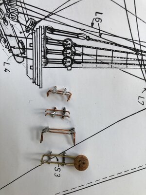
Other kits have similar jigs, but of course with up to three deadeye separation distances, you need multiple jigs. Taking the distance apart from the plans (and scaling accordingly, I bent some double lengths of brass and copper wire and then drilled holes in some scrap wood and placed the bent wire between them. I then soldered two 'support' pieces of wire to hold the jigs in place. Below are my 'rough' but effective jigs (I am not neat with a soldering iron). The mizzen deadeyes (one length) are a different distance to the main and foremast lower sections (second length), and the spritsail mast and topgallant/topmast separations are different again (third length).

t.jpg

And below I show how it is used in a shroud rigging to set the deadeye separation distances to be the same height along the sides of the ship. Note too, that I am using three seizings which I think is correct from the real Vasa.

IMG_7956.JPG

Time Elapsed: 1805 hours

Regards,

PeterG
 

Attachments

  • Img_7982.jpg
    Img_7982.jpg
    248.7 KB · Views: 23
Last edited:
I have touched on this in an earlier post, but I wanted to generate a list of the various scaled rope thicknesses to be used. To this end, I have used the a masters thesis entitled "La Belle: Rigging in the Days of the Spritsail Topmast." This paper by Catherine Corder (2007) is a particularly useful document showing relative rigging sizes. Another indicative listing is from Thomas Miller's 'The Complete Modellist' of 1667. A table from this is shown below:

1619485753450.png

I refer you to the website of the http://www.bruzelius.info/Nautica/Rigging/Miller(1667).html for additional rope size specifications (eg Main Topmast, Foremast etc).

Now before we go too far, we have to remember that circumference of a rope and diameter are NOT the same (related by pi or 3.1414). If you multiply the diameter by pi, then you get the circumference of a rope. The above dimensions (as far as I can interpret, were circumferences (in inches). However, the simplest method for us to measure the size of ropes for models, is to wind a known number of turns of the rope around a dowel or ruler with their windings adjacent to each other, not too tightly, but with no spaces between. By measuring the distance that the windings lie across and dividing this by the number of turns, the rope diameter is measured. Obviously the more turns, the more accurate the diameter is determined, but about 20-30 turns is practical and seems to work OK.

Once we have the diameter, we then have to convert for scale of our ship. So, by example, if I have 24 turns over a wound distance of 2.0 cm (20 mm), then the diameter of the rope is 20/24 = 0.83 mm and at a scale of 1/75, the size of the actual rope represented is 0.83 x 75 = 62.25 mm or 2.45 inches in diameter (or a circumference of 7.69 inches) - a big rope but not unrealistic for a shroud or stay.

I have generated an Excel spreadsheet of my proposed rope sizes (below). I have tried to choose what rope sizes were likely to have been used on the Vasa and reading various build logs and articles has compiled the following list. These sizes are not going to be correct, but hopefully I am reasonably close. The spreadsheet too is an evolving thing, as it will be expanded as the build progresses. Also note that I have DIYed my own ropewalk, so I have a reasonable amount of control of the rope thicknesses I create. I am still learning as to what final diameters I create by a particular source thread, but the more I do, the better I get.

1619488888376.png

An Excel file of the above is below.

Hope this helps,

PeterG
 

Attachments

  • Rope_Sizes_PeterG.xlsx
    12 KB · Views: 29
Last edited:
Fantastic Peter. Thank you for posting this information! I have attached two other tools I have come across that you (or others) might find useful.
 

Attachments

  • Period Ship Scale Tables.xls
    1.6 MB · Views: 52
  • Rigging - size of rope and blocks - Final.xls
    5.3 MB · Views: 35
I am working my way through the standing rigging and it is taking a while - not surprising. But, as a background task, I have been getting familiar with the terms and arrangement of running rigging on the Vasa.

I have two Belaying and Rigging Points plans available. In fact there is a third derived from the other two in German, but its origins are the same so I will discount it (and my German is not good to interpret some of the points). Note that I am here referring to published rigging plans of the Vasa, and not those from the ship kits (Billing, D'Agostini or Artesania Latina). I have not seen the plans from Corel or other manufacturers.

One plan is derived from the numbered index Plan drawn in 1970 (originally) by Vasamuseet and then updated later (about 1979/81) according to Fred Hocker. The second rigging plan is by the German, Stolt in 2009 derived from experience on the Gothenburg III replica (refer http://www.jans-sajt.se/contents/Navigation/Modelling/R_Wasa.htm).

My problem is that I have a few inconsistencies between the two plans. These plans are shown below. For ease of understanding of the ship's layout, I am editing the 1970 plans with labels and English titling at each belay point. While doing this, I have come across the inconsistencies and I am hoping some people may be able to assist me with some answers :

Rigging+Deck_Secure_Points_English.jpg
ABOVE: The updated original 1970 plans from the Vasamuseet.

Rigging+Deck_Points_1.jpg
ABOVE: The plans from the Stolt belaying layout.

The plan inconsistencies involve:

1. The first belaying pin rack on the beakhead has a Spritsail Clewline in the 1970 plan. On the second pin rack however is a Spritsail Garnet (number 8 in the index). I thought a Clewline and a Clew Garnet were the same thing. What is going on here?

2. On the 1970 plan, a numbering index is used to determine the belaying points. There are TWO Number 42s which is confusing.

3. In the 1970 plans, the Spritsail sheet is marked as belaying through a sheave midships on the outer side of the ship, then belayed on the midships kevel. In the Stolt plan, the Spritsail Sheet is belayed at the rear of the Fore pinrail. What is correct?

4. There is also a conflict with 1970 plan number 63 (Mizzen Topsail Bowline) and on the Stolt plan, it is labelled as the Mizzen Topsail Brace. A brace cannot be a Bowline (can it?)

5. The same appears for number 68 which is labelled the Mizzen Bowlines, but on Stolt it is the Mizzen Brace.

6. There is some confusion in the naming of the Tyes on Stolt's plans. I think he is refering to a Top-Rope as defined by R.C. Anderson and on the 1970 plans in which this explains it. Note the mizzen had no top-rope arrangement.

I hope someone can assist. Overall, the two plans are very close, but the differences will force me to make decisions as to which is correct.

Regards,

PeterG
 
Moving on with the standing rigging. I have begun by fitting the stays to each mast. I was not happy about adding tension from the tackles and shrouds to pull aft, when there was no forward support. In the picture below you can see the mainmast with the stay and a mouse fitted with the beginning of fitting the tackles and shrouds around the base of the mast section and running through the tops. You can also see the top-rope fitted with block and fixed on the starboard side. The shrouds have been positioned in an 'order' around the mast with starboard/port each side and having tied off the loop around the mast.

IMG_7842.JPG

The tackles were the first to be positioned, ahead of the shrouds and these were adjustable via their lanyards to provide some rear tension before the shroud lines were attached to their deadeyes and lanyards. The tackles each run from the top to a violin block and are seized to it. The lanyard for the violin blocks then go down to a block which is secured to the chainplate by a hook, secured to an eyebolt. The ship shows this arrangement clearly as shown below:

Chainplate.jpg

In the above image, the initial lanyard end is secured to a becket (ropeline) around the lower block and then up to the violin block twice, to be finally belayed around the small rope between the hook and the lower block. I am not sure if when preparing to sail, the actual Vasa would have been rigged this way. To me it would make more sense to have had these tackle lanyards available inboard so greater or lesser tension adjustments could be made while sailing. Not sure about this but at this point, I am rigging the tackles as per the ship in the museum.

The violin blocks were an issue as these were not provided by Billing Boats in the kit. As such, I fashioned my own, and used the high resolution images of the Janssen model (link https://www.modelships.de/Vasa_II_Janssen/dIMG_5926.jpg) as shown below:

Block_Violin.jpg

This site is especially useful as the photos provided are really high resolution. In the image, you can see two violin blocks for the tackles. My blocks are not as good but relatively easy to make and with a little stain, they worked out satisfactorily.

A start to the shrouds was made for the mizzen mast (as there are only four shrouds to fit and this is shown below, with a central tackle line already fitted. Of course placement of one shroud on one side of the ship, has to be balanced with a similar shroud placement on the other side of the ship. To spin the ship around using the rotatable base plate/platform I am using, enormously speeds up this process (rather than repositioning the starboard and port sides manually each time).

Nothing at this stage is permanently tied off on the lanyards as there will inevitably be some stretching and adjustment required. This is particularly so as ratlines, movement and tension seems to be a difficult thing to master. How much tension should you apply to the shrouds? Obviously you can't tighten until there is distortion of the mast uprights but you need a reasonable tension to effectively apply ratlines - It is a balance!!

IMG_7980.JPG

Elapsed Time: 1855 hrs

Regards
PeterG
 
I remember reading in a build log that the upper railings could be troublesome to fit if too much rigging was in the way. The upper railings sit above the molded white railings already in place and which serve to hold the belaying pins and running rigging points. Early ideas of belaying pin rails fitted at strategic points around the ship were discounted by Fred Hocker, and these railings were the preferred locations. There are some belaying pin racks on the ship, for example there are four on the beakhead, but on the main deck, the railing, the knightsheads (with crossbars) and the kevels appear to have been the main belaying points. So, above the railing, is a second, much thinner and less robust railing which on most models I have seen are finished in natural wood rather than painted, although some are (see the Janssen German model example in post #206 above.

The Billing kit supplies these railings as laser-cut plywood in sections with four per side. The different sections have vertical support posts which go up and down depending on the rake of the deck and the steps in the belay railing onto which it is to be supported. The method of securing the upper railings is not described in the BB instructions but assumedly, it is by gluing the posts to the belay railing and providing temporary support while the glue dries. Obviously this would not be especially strong, especially if these railings were to be fixed before rigging and then subject to bumping or movement while rigging was getting done.

So, what I have done is try to increase the strength of the support for these upper railings is to add a series of brass wire pins which are attached into the upper railing support posts and then drilling into the belay railing beneath. With gluing and these pins, the railing actually feels quite firm. Also, because of this support, the railings can be permanently added after standing rigging. They may be able to be added after running rigging, but I will wait and see as I am not up to this stage yet.

Below I show one of the upper rail sections with the brass wire pins inserted into some of the support posts. I chose the posts depending on the shape of the railing and the belaying railing as these of course are not straight, but follow the curvature of the ship decking.

Img_8057.jpg

Also, it appears that the upper railings were positioned centrally over the lower rail (see picture below). The holes I have drilled
in the lower railing to support these upper railings reflects this. The railings are quite fragile and placing the brass wire pins was a delicate job as you had to be accurate in the drilling and not piece the sides of the support posts. The depth of the pin to be exposed too had to be measured and cut off at a depth which did not go right through the lower railing, as this would then be seen from the outside of the ship.

Railings.jpg

This approach of having pre-fitted the upper railings and then taking them off once fitted and measured should help for the rigging phase. I think I should be able to place and position these without too much trouble at a later time without the concern of knocking or bumping the fragile railings. It would not be a nice job to have to fix any broken timbers with the rigging ropes in place. Better to be safe at this stage while I still have relatively easy access to the lower railings.

Elapsed time: 1860 hrs

Regards,

PeterG
 
Кроме того, похоже, что верхние перила были расположены по центру над нижними перилами (см. Рисунок ниже). Отверстия, я просверлил
в нижних перилах для поддержки этих верхних перил, отражают это. Перила довольно хрупкие, и установка шпилек из латунной проволоки была деликатной, так как вы должны быть аккуратными при сверлении, а не кусать стороны опорных стоек. Необходимо было измерить глубину открываемого штифта и отрезать его на такой глубине, которая не проходила бы прямо через нижние перила, так как это было бы видно снаружи корабля.

Перила.jpg
PeterG, судя по фото, стойки верхних перил проходили рядом с нижними, а не заканчивались на перилах. Посмотрите фото, которое вы прикрепили. Я обозначил это стрелками. Может я ошибаюсь и ракурс фото нехороший, но я так посмотрела.Railings.jpg
 
Peter,

Thank you for this thoughtful post. I'll try to remember this when I get that far...

I have been known to 'rail' (pun intended) against DeAg for the use of plywood for precision parts rather than solid stock - it would seem that BB does the same. Painting becomes a viable solution to hide the layered face. Will you keep it dark or paint it light (gray/white) as you have done for the lower railing?
If I could make a suggestion, it seems the actual railing is more ornate than a flat piece of plywood...therefore I would suggest adding a radius to the existing piece on the top edges, then capping it with another thin strip of wood. That would simulate what is pictured above, and make it more ornate.
 
Last edited:
For those without a Russian translator installed, Alexander has posted the following in Post #208:

"PeterG, judging by the photo, the posts of the upper railings passed next to the lower ones, and did not end on the railing. Look at the photo you attached. I marked it with arrows. Maybe I'm wrong and the angle of the photo is not good, but I looked at it that way."

To Alexander:

I believe you are correct and I had not noticed this before. I have uploaded a better photo of the ship starboard side below (taken in the museum in 2017) and this clearly shows what you are saying, with the upper railing supports going through the lower railing and secured into the ships side planking. Well spotted!! Unfortunately, with my current build and embarking on the rigging, I don't think I am going to be able to change this now, but a good 'heads' up' for other builders!!

In Russian:
Я считаю, что вы правы, и раньше я этого не замечал. Я загрузил лучшую фотографию правого борта корабля ниже, и это ясно показывает, о чем вы говорите, с верхними опорами перил, проходящими через нижние перила и прикрепленными к обшивке борта корабля. Хорошо подмечено!! К сожалению, с моей текущей сборкой и принятием такелажа, я не думаю, что смогу что-то изменить сейчас, но это хороший сигнал для других строителей !!

IMG_6673.JPG

Many thanks Alexander,

PeterG
 
To Paul (docattner), the use of plywood I deplore in these kits. I don't have a major issue where it is a panel or surface that has enclosed edges, but where the layered, sandwich edge shows, it is a real negative. You will note that Dean has added the suggestion of laminating or covering the upper railing plywood with a 'real' layer of shaped timber. I will have to look that. Thanks for this suggestion Dean, it is a good idea. I have used shaped wood for the strakes below my lower railings and it works really well. I made this simply by taking some stripwood and making a shallow cut with a 'rounded' blade on each side, then sanding and it worked well. I possible could do something similar for a top layer added to the upper railing as you suggest. Trial and error is our friend!! Also see my next post about some timbers I have been using recently.

To also answer your additional question Paul, I had intended to leave the upper railing the darker, stained colour. My lower railing is currently white to contrast the red and yellows of the clinker cladding below and I think the natural timber look is more appealing, but in light of what you say with the plywood, painting to match, a similar white, would largely hide the plywood laminations. I guess this is what Billing's were relying on in using the plywood in the first place. Equally, these upper railings are so thin at this scale, that if they had used 'real' timber, it would be even more fragile and prone to breakage both in transit and in mounting. Also, of course, the use of plywood makes it easy for the manufacturer to make by use of laser-cutting of the plywood.

Thanks,

PeterG
 
In my Post #206, I mentioned that for the mast tackles, I was going to use violin blocks. This is an interesting type of block used on the Vasa. In 'The Rigging and Gun Tackle Blocks of the Swedish Royal Warship Vasa" thesis by Howe (2011) the author describes the blocks below:

"The second largest group of double blocks have elongated, figure-of-eight shaped shells containing two sheaves of different sizes arranged end-to-end in the same plane (see below). These are easily recognizable as fiddle blocks. For four of the five examples, the two sheaves are the same thickness, indicating that these carried the same size cordage and were used in rigging what are known as long tackles—a name reflecting the elongated blocks that streamline the profile of the tackle. "

The shape of these blocks is as:

Fiddle_Block.jpg (after Howe, 2011).

Note that my terminology (a violin block), is a newer version of a 'fiddle' block, due to the shape and the likeness to the musical stringed instrument (violin, fiddle etc). It appears from a number of Vasa models that the most prominent usage of these blocks was the tackle lines used in supporting the back (aft) tension applied to the masts. Refer to post #206 for an example of this.

So, if these blocks were to be used on the ship, and the Billing kit manufacturers saw fit not to include them, I thought I would have a go at making my own. The first task is to choose some suitable wood and then the mechanics of shaping the wood in my meagre ship shop. I do not have any fancy milling machines or routers etc - only a small power saw, files and sandpaper. My thinking was, as I needed about 16 of them, I would attempt to make the 'shape' of the scaled size and then use the saw to simply cut them the correct thickness, drill, file, sand and finish.

What timber to use? In Australia, where I live, I don't have access (other than by internet purchase and mail) to local hobby shops or boutique timber yards. I could have opted to buy some timber from overseas and have it sent over (maybe pear, cherry, or other exotic timber etc), but following a recent working trip to Tasmania (pre-pandemic in March 2020), I visited Macquarie Harbour and Strahan on the West Coast. For those of you who know this place, it is the ocean opening to the famous Franklin and Gordon rivers, a scene of demonstration and unrest in the 1980's around the construction of hydro-electric dam sites. This remote and isolated area however is especially known for the native forests to have a reasonably prolific abundance of Huon Pine. Below I provide some background to this amazing timber:

"Huon Pine only grows in the wet, temperate rainforests of South West Tasmania – on the whole planet! ‘Lagarostrobus franklinii’ (its proper name) is not actually a pine and is the only member of its family, so a pretty unique tree which grows extremely slowly, averaging just 1 millimetre in girth per year. They can grow to be 2,500 years old which means some of them started life BC! Add to this the fact that they do not start to reproduce until 600 to 800 years of age and you have a very special tree whose timber also has remarkable properties. The timber has a very high oil content, methyl eugenol to be precise, which renders it impervious to insects, waterproof, and imbues it with its characteristic sappy perfume. The high oil content also means the timber can be bent, shaped, worked and sculpted without splitting and finishes to a superb, fine lustre. Pale straw coloured when first cut, it ages to a rich honey gold. Woodworkers love it!"

"The early settlers discovered the remarkable properties of Huon Pine and saw its potential for boat building, resistant as it was to those perennial problems of the boat builder, marine borer and screw worm. It turned out to be the best boat building timber in the world and was exploited heavily in the early days, driving a huge industry based on this ‘green gold’.

Interestingly, concern for the future of these venerable giants started early in the last century – even back then it was apparent that there would be no next generation of trees to be had, their slow growth precluding the possibility of plantation farms.

The felling of green Huon Pines stopped completely in the 1970’s after a consensus that it was neither sustainable nor prudent to cut down trees that were 1000 years old. However, a careful stockpiling operation was begun when trees were felled and collected prior to the flooding of several valleys to create dams for hydro electric schemes. For decades these logs were tied into huge rafts and left to float unperturbed on the water until needed. The stockpile created when Lake Gordon was flooded in 1972 still supplies the majority of logs released for use each year."


During my trip, at an antique sawmill, I purchased a few isolated offcuts of this remarkable timber. It is a light, yellowish, extremely dense softwood which is strong but ideally suited to scale carving and working. I decided to give it a go for the fiddle blocks, so I cut a strip of the correct size for the scaled blocks and then commenced shaping it. To say it is a pleasure to work with is a massive understatement. The sawdust is like talcum powder and the smell is divine!! I shaped a small length of the stripwood into the shape required and started cutting off the thickness of the blocks, before drilling and filing the side rope indentations.

IMG_8063.JPG

The colour of the timber is a light yellow/brown but I needed it to be a darker more brown colour, so I dipped a sample into some stains and chose one that I thought was satisfactory. Below is the final product. These still need a bit of sanding and smoothing, but the result is quite acceptable.

IMG_8064.JPG

I then placed the blocks into the tackle lines and rigged the lanyards. There are three sets of tackle lines in this part of the main mast rigging and it looks OK. Only one thing I could have additionally done and that was to slightly engrave a groove around the rigging holes to represent the sheaves which would have been in the blocks.

IMG_8065.JPG

I am really pleased I was able to use some of this amazing timber on my ship as its history and where it came from is special. Hopefully I may be able to shape some more items for use from the Huon Pine.

Elapsed Time: 1890 hrs

Regards,
PeterG
 
To take a break from the stern and galleries, I turned my attention to the hold gratings. Billing Boats supplied these in the kit as laser-cut plywood. The ply was a relatively light brown which was not similar to the decking or darker mahogany timbers I have used, so I did a bit of experimenting with a mahogany stain and came up with a good wash (water based), which I then applied to the various gratings. These gratings were cut from the laser cut sheet easily, but the individual pieces of ply that had to be extracted from the 'holes' of the grating took a long time to be cut out and removed cleanly. While the plywood and laser cuts were relatively clean, the instructions described (by way of a picture), as to how to fit individual timbers in a criss-cross fashion to form gratings. I can only assume this is how earlier Billing kits had their gratings made. I have seen build of gratings made this way and while it is a lot of work, I think it probably creates a higher quality and more authentic grating appearance. Either way (laser cut plywood or individual, manufactured gratings), they have to be better than plastic, which I also suspect (from comments in other Vasa builds) were used in some model kits of the ship.

To increase the detail on my gratings however, as well as the stain, I also scribed the timbers and cut through the top layer of the plywood along each timber. This gave the look of individual timbers having been used for the grating vertical and horizontal wood and in the end, looks quite good. I show a picture below with the three stages of modification (the originally cut out laser plywood (left), the stained and scribed grating (centre) and the finished re-stained finished grating (right):

View attachment 115169

The next task I decided to do while I had good access to the newly painted galleries, was the painting of yellow contrasting 'scallops' along the gallery upper surfaces. This is not something I have seen in many Build Logs, but it is present on the famous Berlin Vasa model, the ship as drawn by Bjorn Landstrom (in his Vasa book of 1988 - and before the current research on the ship), plus the researched De'Agostini model Vasa. Although I am not sure of its authenticity or appearance on the original ship, it does add a look that I quite like. This feature had to be done before any artwork sculptures were added so now is the right time. Below I show an image of the Berlin Vasa and its distinctive scalloping along its galleries.

View attachment 115170

As I have now decided to try this (on a 1/72 scale model - silly me), I had to come up with a way of creating these scallop lines with suitable paint. I figured that if the end result was not appealing, I could repaint the gallery surfaces. So, how to paint the fine lines that would be required. I tried a number of paintbrushes (size 0 and 00), but I could not get a consistency that could be maintained. Also a paintbrush with the curves of the scallops was really hard to shape. I then thought, how about a paint pen. You can buy these and they are really good, but I could not get one that had a fine enough felt point that didn't thicken after a couple of scallops being drawn on the relatively rough timber surface of the clinker planking. Is there another type of pen that would allow the paint to flow, but could apply its line when held fractionally above the surface of the timber. My old professional drafting days came up with the idea of a drafting pen. In the back cupboard (after some searching), there was my Rotring drafting pen set and all the protractors, scale rulers and curves!!!. I realised that the thickness of drafting ink and that of paint were considerably different, so I needed to do some experimenting with diluting the paint (with turpentine as it was an oil-based enamel). I trialled some acrylics, but the cover was just too thin and transparent, so it had to be oil-based enamel. After a lot of trials and experimentation, I finally came up with a relatively strongly diluted mix of enamel paint and turps which flowed through the fine 0.2 mm knib of the Rotring pen that I found to work the best. Below are some photos of the pen in use and the final product.

View attachment 115171

View attachment 115172

Although not perfect everywhere, I think the effort and effect is quite good. You have to also take into consideration that there are a LOT of sculptures to be added to the galleries and turrets so many of the poorer scallops will be hidden.

One other thing I added too, which can be seen in the above photograph, are the large number of infilled vertical, turned timbers that lie between the two galley base frames. These I turned out of toothpick wood and then cut to the required length. They also add some detail that is seen on the original Vasa.

Time elapsed: 805 hours

Regards,

Peter G.
The toothpicks do add something to your build!
Vic
 
Thanks Daniel. For those not accessing the list I recently placed on the post in the Vasa build log by Dockattner, I listed a range of links to previous logs and other articles on different forums. This list (with some additions) I provide below.

The research of build logs can take a long time. To me too, it is frustrating that there are a number of model ship build log forums (eg SOS, Model Ship World and
modelshipbuilder etc). My favourite build logs for the Vasa (wood builds only) with other links, include:

Nazgul (Billing Boats kit) plus Nazgul
Doug Buchanan - Billing Boats
Mar3kl - Billing Boats
Karleop - Billing Boats (restoration)
Clayton - Scratch build
Ulises - Corel kit
Fmodajr - Corel kit
Md1400cs - Corel kit
Marktiediens - Sergal 1:60 scale
Martyn - Corel build
JanV - Corel build
Snoepert - DeAgostini build
Peter Jenssen - Scratch build based on Corel
MGovey - Billing Boats
Kageecanuck - Corel kit
Frankberge - DeAgostini
Short John Bronze - Corel kit
Sparrow - Kit assessment

Other resources:

Painting Vasa Sculptures

DeAgostini instructions: https://www.model-space.com/gb/build-the-vasa.html
Actual Ship video https://www.youtube.com/watch?v=u2hbUq2rN_I
Various website resources http://www.modelshipbuildingsecrets.com/resources.html
Useful forum: http://www.modelshipbuilder.com/news.php

Hope you find this helpful.

Just an update on my Vasa build - Its progressing but slowly as I am tackling the ratlines. Will post an update soon.

PeterG
 
Peter,

Very nice links to other builder's work - good resources indeed.

FYI: for builders of the Corel kit, if you intend to also fully rig including adding sails - the Corel rigging sheets are very very poor.

I used the Billings Vasa rigging sheets for adding sails to my bashed Corel build (md1400cs [thanks Peter, for my link] )
Those seem to be excellent - that said the actual Vasa rigging is a partial mystery, and mostly guesswork based on other contemporary Dutch ships of that time.
The 1/10th at the museum, according to Fred Hocker, also incorporated some English rigging details from that time in order to completely rig the museum's 1/10th

Your current build is coming along very nicely!

Regards,
 
Thanks John. You are absolutely correct about the rigging as little was recovered from the ship (understandably) and as Fred Hocker says in the wasadream web forum. In addition to the Billing Boats rigging plans, I have used the 1970's plans published by the Vasa museum (and available, (again from the wasadream link here). These plans I think are slightly more accurate and in fact, it is likely that the Billing plans used these with some simplification for their kit. The more recent kits by DeAgostini and Artesania Latina have published colourful, progressive step-by-step instructions, but no rigging plans. While their instructions are well documented and produced, the technical necessity of having plans available to me, is essential.

To be fair, the Corel kit was originally formulated and produced soon after the ship was raised and there wasn't the detail, study and research available to this kit's manufacturer until later. That said however, I am not sure if they have updated the kit in design and in keeping with the later work. It would be a big job!!

PeterG
 
I have not updated the build log for a little while and so I thought I would put in a couple of new entries.

I have completed the tackles and the shrouds as I showed in the previous build post. My next item (ahead of ratlines), is the futtock staves. From research I have done, there is little evidence of the nature of these on the ship. They may have been solid (probably of timber), or they may have been a thick rope bound to the shrouds to separate them near the tops of each mast section. From R.C. Anderson, he describes them as being usually timber, but thick rope was also a possibility. In fact, the ship in the museum I think (from a fellow Vasa visitor), says that the the futtock stave is rope, but I am not sure that is correct. A picture I took at the museum could be rope or timber (see below, for manin mast section and top):

Futtock_Stave.jpg

I am opting for a small length of rounded rod. This rod I have bound to each shroud about the same distance below the top as the mast head extends above the top (as per R.C. Anderson). The angle of the futtock stave too has to match the inclined angle of the top for each mast section. In the foremast this is nearly horizontal, but of course on the mizzen and main masts, this angle is quite severe (about 7 degrees forward from the horizontal). The consequence of this is significant as it implies that as the ratlines come up from the deck, the angle must match the futtock stave. Below I show the futtock stave for the foremast (which is near to horizontal).

IMG_8075.JPG

I note on some models the angles of the ratlines varies. For example with the DeAgostini kit, the ratlines on the mizzen, foremast and upper mast sections have ratlines which are about horizontal, but are raked forward for the main mast (see below).

DeAg.jpg

In the case of the Artesania Latina kit, all ratlines appear near horizontal, forming an angle with the decking and rails which would have been an issue for the sailors climbing aloft (see below).

ART_Lat.jpg

My preference is to angle the ratlines parallel with the deck railings at the base and then if need be, slightly increase the angle progressively upward to match the top and futtock angle near the head. As said earlier, there is little clear evidence on what was 'actual', but to my eye, this appearance is preferred to that of horizontal ratlines.

The distance the futtock staves (for the main mast at least) provide between the deck railings and the staves provides for 26 ratlines (as per the real ship). Over the shroud length and at scale, this represents a ratline separation of 16 inches (or 40.6 cms) which seems to be about right for ships of that era. The actual modelled ratline distance apart therefore needs to be 6 mm. Note that I am using Clove Hitch knots on every ratline/shroud crossing - even at the ends followed by a diluted PVA-water dab of about 1:3 mix.

Colour and rope thicknesses are also important. As regards the colour, I prefer the standing rigging to be darker in colour than running rigging (to provide a contrast between the two). There is some argument regarding the possible tarring of standing lines (such as shrouds), but little evidence to support it on the real ship (after Fred Hocker). So, it amounts to appearance and preference. I have chosen a darker brown/black for my shrouds and a dark brown for the ratlines. Sizes selected are 0.58mm (scaled) or 43.5mm actual or just under 2 inches after the tables of the book Mondfield. Ratlines are to be 0.16 mm (or 12.1 mm actual or 0.48 inches) diameter. I have some (??) control over sizing as I am making all my own ropes (via a DIY ropewalk).

Having gotten into the ratlines now, I can not believe the metres of rope required!! Admittedly there is quite a bit of wastage but still, it is many metres.

Time Elapsed = 1946 hrs

Regards,
PeterG
 
Back
Top