VOC ship The Prins Willem (scale 1:75) Year 1651

Select your sources carefully.
Thanks Ab, that makes sence, in all the years things could be changed. Corel didn"t install the belaying pin arch on their model, like the model in the museum.
Yesterday I study the chapter about the bowsprit in the book Anderson. Took me the whole day to understand and find out how things are installed. But I understand a lot of it now.
I think Anderson is a good source to follow. Even the model in the Rijksmuseum. Keeping in mind you say about changes in years.

The arch is already installed on my model. Just let it be there, for a while and see if it is necessary or not.
The model in Friesland looks good but I will not use it as source.
 
Question about the fore castle deck. This is open on the museum model?
 
Yes, it has to do with history. The Prins Willem was a VOC ship (East Indiaman), which was hired by the Admiralty to serve as a warship. Therefore changes were made to the ship: The forecastle deck was removed completely to give room for more guns on the fore side of the upper deck. Ketting knew about this, but his curator (Bas Kist) refused to let hem make changes on the original model. Therefore he was allowed to build a new model with all the adaptations he had noticed. The whole affaire ended in the publication of the book you are using as a source now. It was the first thorough study on 17th century models in Holland and an inspiration to many, even though there were many mistakes and inconsistenties in the book. Thast’s how it goes when you are first. :)

I’m not sure what you mean by the ‘arch’. Maybe a picture?
 
I’m not sure what you mean by the ‘arch’. Maybe a picture?
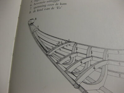
Herman calls this "Betingbalkje" #2

IMG_1614.JPG

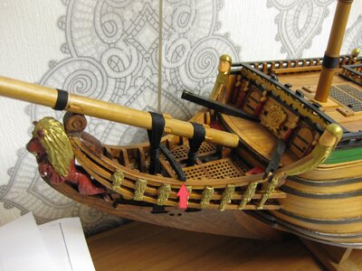
My model

IMG_1613.JPG
You can see it is easily to remove.

Anderson doesn't describe / mention this in his rigging methods.

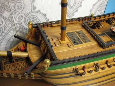
So this deck shouldn't be like this, mentioning that the extra gun ports on the bow are not installed in my model. So it looks like how the ship original was build.
IMG_1618.JPG
 
Last edited:
I'm thinking about the change in the rigging in those years. 1650 was the change that gammoning blocks where installed. Maybe that is the reason this Betingbalkje disappeared on the model. I'm just guessing.
 
No, the betingbalkje was characteristic for Dutch ships. Leave it where it is. On Witsen's pinas there are even two of them. It makes sense, because one of the reasons to be for the beak head was the handling of several ropes form the foremast and bowsprits. You will need every belaying point you can get.

That Anderson mentions a date for the gammoning block does not necessarily mean he is right there. The original Prins Willem is proof of the contrary...

You can see the absent forecastle deck on the original model here:
Gescande afbeelding 3.jpg
 
Anderson said indeed that he has no proof about the date, because he found any evidence. That's fair.
No, the betingbalkje was characteristic for Dutch ships. Leave it where it is.
Oke, I leave it. It looks also good.

You will need every belaying point you can get.
The bowlines of the fore course and topsail need a point to belay them. There will be otherwise too many ropes going to the fore castle. And I can put the blocks for the brace of the spritsail on it. Yes I think I will need these belaying points. Like you said earlier before to "look for logical locations to belay your ropes."

It's all clear now. Thank you Ab, you're been very helpful clearing this. And I keep your advice in mind to look Logical. :)
 
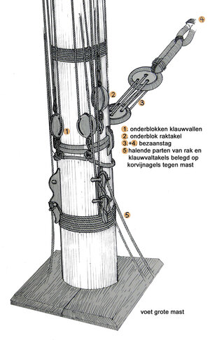
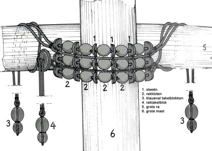
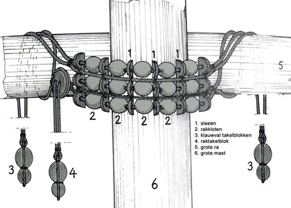
Herman Ketting was talking about the "klauwvallen" or other name "Piekevallen" all Dutch words.
I now this but this is a tackle to lift the gaff

Does anybody know what Herman is meaning in English? Or that this is incorrect?

In this one #1 and #5
mastvoet grote mast.jpg

In this one #3
rak grote mast.jpg
 
Last edited:
As to the blinde (spritsail) in your pdf: the deadeyes for the 'Spanish lifts' should be in the middle of the half yard.
What Herman means with klauwvallen: I really can't guess.
 
And apart from the fact that square rigged ships did not have ‘klauwvallen, the last Ketting drawing in post #169 shows ropes and blocks on the front side of the sail, which is nonsense. As I said, be careful with selecting your sources.
 
Last edited:
As to the blinde (spritsail) in your pdf: the deadeyes for the 'Spanish lifts' should be in the middle of the half yard.
What Herman means with klauwvallen: I really can't guess.
Thanks, I see it. The picture of you shows it. The standing lift should also placed to the outside. About one third. I will change it.

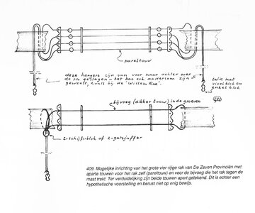
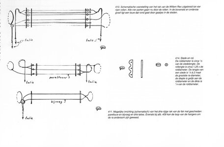
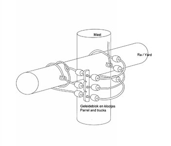
About Herman, I really have a doubt about the picture of the parrels. These 2 ropes what he calls klauwvallen. Never seen this way. I know there are tackles attached to the parrels to lift them up and down. This what he draws look like something to help fasten the parrels tight to mast.
 
yes, this is helpful.

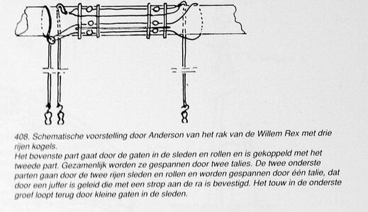
But looking to the parrels, I see that the William Rex is simular to Herman Ketting's drawing

Blom:
blom.jpg

Herman:
rak grote mast.jpg

The haliard (talie) goes behind the mast down, and wil belay there on a rope around the mastfoot. So the rope will go between sail en yard to the back and down.
The second time I see this construction.
What is logical now???
 
I found in the book also that this was how Anderson draws it.
blom02.jpg

The explanation is that when the wind blows from behind, they could tighten the yard to the mast, something about to better brace the sails.
But he calls thes ropes talies (halyards)
Time for me to study Dik to.
 
(Blom is not involved here. He died before he was up to the rigging of his model. It was Dik who made the drawing.)

I can only think that the outer lines (3) were hauled backwards between yard and sails, which is not particularly an elegant solution. Honestly spoken I never dealt with such complicated parrels and trusses. They were used when the wind came from the back, to keep the yard against the mast. When close hauled the trussed were loosened to allow the yard to be braced over one side. I can hardly imagine such complicated constructions were very practical. If I were you I would simply choose for the 3-row parrels.
 
Last edited:
(Blom is not involved here. He died before he was up to the rigging of his model. It was Ketting made the drawing.)

I can only think that the outer lines (3) were hauled backwards between yard and sails, which is not particularly an elegant solution. Honestly spoken I never dealt with such complicated parrels and trusses. They were used when the wind came from the back, to keep the yard against the mast. When close hauled the trussed were loosened to allow the yard to be braced over one side. I can hardly imagine such complicated constructions were very practical. If I were you I would simply choose for the 3-row parrels.
That was my first attempt, till I saw these drawings in Ketting. Your right about the logical use of this construction. Nice to find out these drawings are not 100% scifi. but the construction with one talie (halyard) makes it easier to make. I will go for that for sure. I have from Hans of Kolderstok an example how to make the parrel and can use that or your example of 3 rows. I will see what is possible on scale 1/75
Rak met mast 15apr16.jpg
Drawing Kolderstok

All is clear to me now and I can go on with the rest of the ropes
Thanks again
 
It takes time to find out everything you need to place the ropes.
I use Anderson's book as main source. When you look good you can find everything you need.

The main course and fore course are almost the same in rigging, so I put them together in my pdf that I make as sort of map.
In the attachment there is the ready part of this.

Coming up next the fore and main topsails
 

Attachments

Back
Top