Wright Brothers "Flyer" 1903

Enjoy your special day
Also from my side a friendly Happy Birthday, Daniel.

HAPPY Birthday-Cake BIRTHDAY
Happy Birthday, Daniel
Hapy Birthday, Daniel! Birthday-Cake All the best on your special day
I sure thank each one of you for your birthday wishes! 70 is a big one for me, seems kind of odd but happy to be here. I'm having a great day with my wife barbequing some baby back ribs.
 
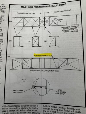
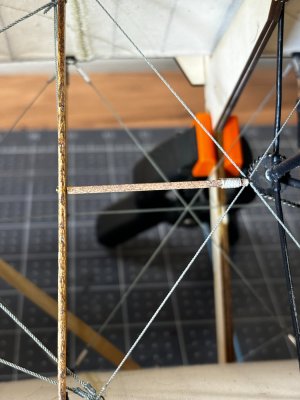
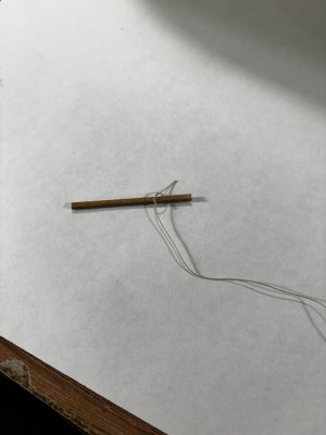
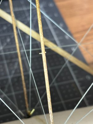
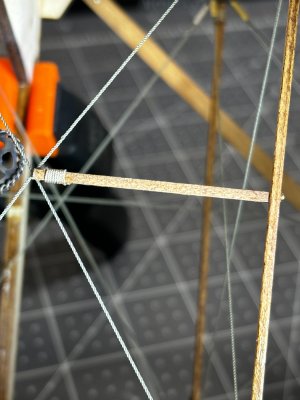
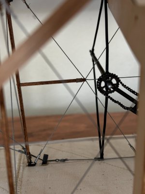
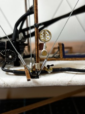
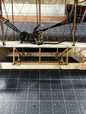
I've got another working update to my build. The rigging between the two main wings is finished; I wanted to concentrate on an interesting item they used in conjunction with the rigging which is a stiffener located just outboard of each propeller stanchion. This added extra support against the torque generated at these locations. The first picture from the plans shows this as detail A.

IMG_0460.jpgIMG_0446.jpgIMG_0447.jpgIMG_0450.jpgIMG_0451.jpgIMG_0462.jpg

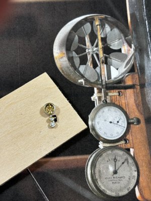
Next are my attempt at the pilot's instrumentation which were just bare necessities. An anemometer, stopwatch, and a tachometer to see engine and propeller rpms.

IMG_0453.jpgIMG_0454.jpg

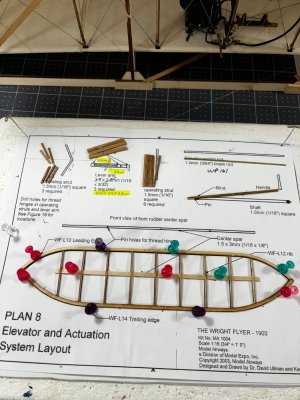
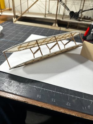
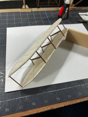
Next, I began work on the forward elevators, called a Canard in modern aeronautics which is a wing forward of the main wing or wings.
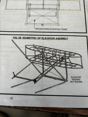
First a 3d of what I am working to.

IMG_0459.jpg

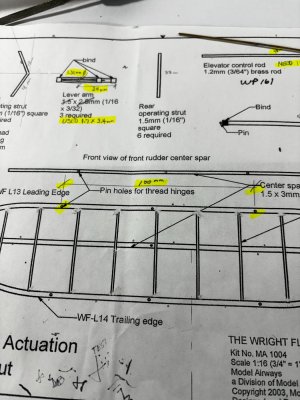
I made some changes to the plan highlighted in yellow.

IMG_0459.jpg

IMG_0457.jpgIMG_0458.jpg

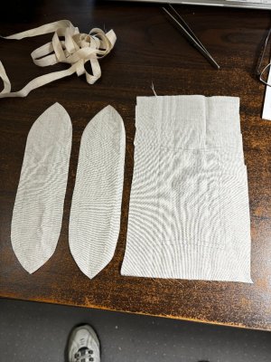
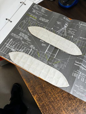
At this point I will have to break out the sewing machine and make the wing coverings for this and the rudders as well.

Thanks for checking in and I hope you all have a great week ahead.
 
Continuing on with the wing coverings, pattern making and sewing. I sewed in the stitching as indicated in the old blueprints I found online. Per description only the top surfaces get covered and the Smithsonian's Flyer is that way also.

IMG_0463.jpg

There's something about the fabric that makes the camera show wavy lines??

IMG_0473.jpg

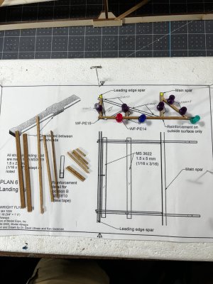
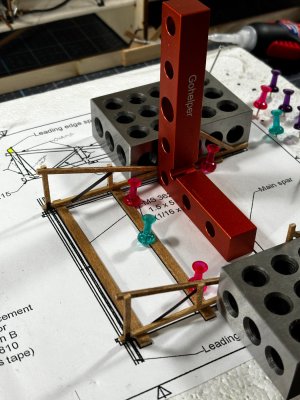
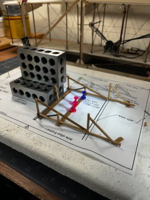
Next, I started on the landing skid which is all stick work so you can see some of my home-made jigs.

IMG_0466.jpgIMG_0467.jpgIMG_0468.jpg

So, the instructions claim there is room under the jig to install the landing skid however I found this to be untrue and had to cut notches in the jig bottom to let the skid fit.

IMG_0469.jpg

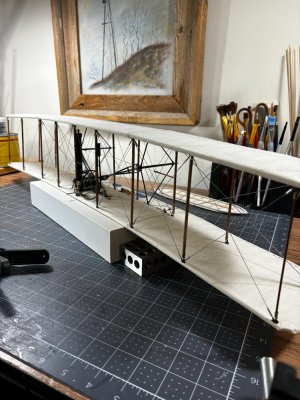
During the notch out process the Flyer fell out of the jig, my heart stopped for a second until I realized this thing is strong as grandma's snuff, the anhedral angle stayed just right and here is a picture of her free from the jig.

IMG_0470.jpg

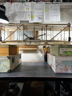
Now back in her jig I have set up a lift system so I can comfortably install the landing skid. Once that is done, she can come out of the jig permanently for the final build out.

IMG_0472.jpg

Hope you enjoy this, thanks for checking in.
 
During the notch out process the Flyer fell out of the jig, my heart stopped for a second until I realized this thing is strong as grandma's snuff, the anhedral angle stayed just right and here is a picture of her free from the jig.
Sometime ’nature’ has to help you to get confidence in the old-fashion structures, Daniel. And gives you the opportunity to make that nice ‘free of the jig’ picture with the curved wing.:)
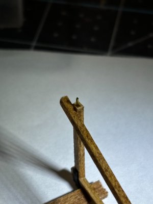
I hit a part of my Balder also once out of the jig. With no damage.
The old designs are not that bad. Only our models are a bit more dependent on the used materials and modern types of glue...... ;)
Ooo ….. and again a nice pair of wing covers.
Regards, Peter
 
Sometime ’nature’ has to help you to get confidence in the old-fashion structures, Daniel.
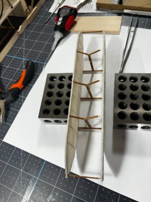
Indeed, Peter during my career I also had the opportunity to assist in the demolition of some old bridges built back in the early 1900's before prestressed precast concrete was ever tried. Their concrete was just as tough as todays with square rebar and all very stout very hard to demolish.
 
Moving along I installed the skid. I added clipped nails into the ends of the struts for better adhesion, the skid will need to carry the weight once I move it out of the jig.

IMG_0474.jpg

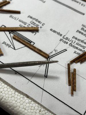
Next is the ships elevator which was more stick work. Here are the steps.

IMG_0476.jpgIMG_0478.jpgIMG_0479.jpg

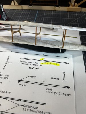
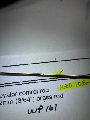
Next, I tried out the elevator control rod which is 1.2mm brass which I had precut to the exact 98mm length called out on the 1:1 plans and WOW it was 6mm too short! So, a word of caution for future builders, make the rod 108mm long. I had to weld (silver solder) the drop off back on and will trim it later on.

IMG_0480.jpgIMG_0481.jpg

If I had measured the hinge points called out on the elevator plan sheet I would have caught this error.

IMG_0482.jpg

Thanks for watching, till next time, happy trails to you.
 
Hey Daniel

I just discovered your blog!

Great piece of craftsmanship that you show

I can imagine that you wanted to do something different for a few ships
Regards
Henk
 
Back
Top