-

Win a Free Custom Engraved Brass Coin!!!
As a way to introduce our brass coins to the community, we will raffle off a free coin during the month of August. Follow link ABOVE for instructions for entering.
-

PRE-ORDER SHIPS IN SCALE TODAY!
The beloved Ships in Scale Magazine is back and charting a new course for 2026!
Discover new skills, new techniques, and new inspirations in every issue.
NOTE THAT OUR FIRST ISSUE WILL BE JAN/FEB 2026
- Home
- Forums
- Ships of Scale Build Logs
- Super Detailing Static Models / Other Genres
- Historical Trailways, Guns, Aircraft, and Cars
You are using an out of date browser. It may not display this or other websites correctly.
You should upgrade or use an alternative browser.
You should upgrade or use an alternative browser.
- Joined
- Sep 3, 2021
- Messages
- 5,190
- Points
- 738

Likewise, but in reverse...I really prefer the metric system, but I just can't get my head around using a comma where there should be a period.
Then we need a lot of input from Daniel ……..At is simplest:
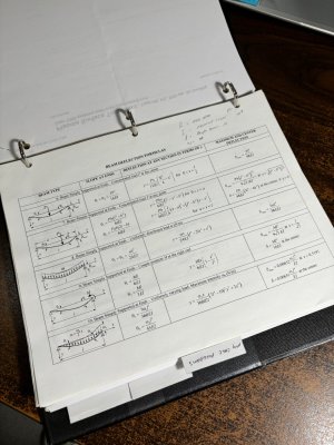
View attachment 470781,
Where F is the applied force, L is the length, or span, E is the mode of elasticity and I is the moment of inertia. Have fun!
Occasionally during my career, I had to calculate the dead load deflection of certain size steel beams holding a uniform load of poured in place concrete for a bent cap. I was never real comfortable doing it and always had my boss check my work though, it was his company. Here is a cable stayed pedestrian bridge I did all the layout on and all the field engineering during its construction. This was one of my favorite projects and out of hundreds of bridges I worked on during my career the only cable stayed one.At is simplest:
View attachment 470781,
Where F is the applied force, L is the length, or span, E is the mode of elasticity and I is the moment of inertia. Have fun!
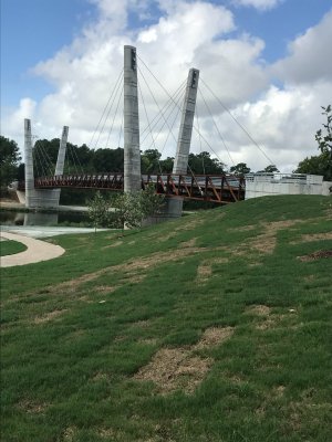
The biggest challenge here was correctly placing the dead eyes at the top of the towers, angle critical to say the least, I designed and built a wood template out of 2x4's and 3/4" plywood that fit into the custom-built metal forms to hold the eyes in place. Another one of those potential career ending opportunities.
I hope this does not come off as bragging, I do like sharing this kind of thing with the right people.
What a beautiful design! Must have been built with oil moneyOccasionally during my career, I had to calculate the dead load deflection of certain size steel beams holding a uniform load of poured in place concrete for a bent cap. I was never real comfortable doing it and always had my boss check my work though, it was his company. Here is a cable stayed pedestrian bridge I did all the layout on and all the field engineering during its construction. This was one of my favorite projects and out of hundreds of bridges I worked on during my career the only cable stayed one.
View attachment 470794View attachment 470795
The biggest challenge here was correctly placing the dead eyes at the top of the towers, angle critical to say the least, I designed and built a wood template out of 2x4's and 3/4" plywood that fit into the custom-built metal forms to hold the eyes in place. Another one of those potential career ending opportunities.
I hope this does not come off as bragging, I do like sharing this kind of thing with the right people.
 .
.It's interesting that the majority of our projects were public money funded projects. Tax dollars at work.What a beautiful design! Must have been built with oil money.
No bragging at all, Daniel. It’s very interesting stuff. Math and formulas: I love it.Occasionally during my career, I had to calculate the dead load deflection of certain size steel beams holding a uniform load of poured in place concrete for a bent cap. I was never real comfortable doing it and always had my boss check my work though, it was his company. Here is a cable stayed pedestrian bridge I did all the layout on and all the field engineering during its construction. This was one of my favorite projects and out of hundreds of bridges I worked on during my career the only cable stayed one.
View attachment 470794View attachment 470795
The biggest challenge here was correctly placing the dead eyes at the top of the towers, angle critical to say the least, I designed and built a wood template out of 2x4's and 3/4" plywood that fit into the custom-built metal forms to hold the eyes in place. Another one of those potential career ending opportunities.
I hope this does not come off as bragging, I do like sharing this kind of thing with the right people.
A beautiful bridge with modern rigging.
Regards, Peter
- Joined
- Sep 3, 2021
- Messages
- 5,190
- Points
- 738

My two cents, by adding the struts and strut wires you're creating a number of parallelograms, where the diagonal brace wires are not of equal length. The wires under tension should keep the anhedral, within certain limits, think elasticity.Anybody want to bet on whether or not these wings snap back to a straight profile once released from the jig?
- Joined
- Sep 3, 2021
- Messages
- 5,190
- Points
- 738

Beautiful suspension bridge. Those deadeyes are indeed stuff for nightmares, not having your math right is having a very bad day.Occasionally during my career, I had to calculate the dead load deflection of certain size steel beams holding a uniform load of poured in place concrete for a bent cap. I was never real comfortable doing it and always had my boss check my work though, it was his company. Here is a cable stayed pedestrian bridge I did all the layout on and all the field engineering during its construction. This was one of my favorite projects and out of hundreds of bridges I worked on during my career the only cable stayed one.
View attachment 470794View attachment 470795
The biggest challenge here was correctly placing the dead eyes at the top of the towers, angle critical to say the least, I designed and built a wood template out of 2x4's and 3/4" plywood that fit into the custom-built metal forms to hold the eyes in place. Another one of those potential career ending opportunities.
I hope this does not come off as bragging, I do like sharing this kind of thing with the right people.
Still, bragging rights granted!
Hi Daniel just catching up here. WOW - very clean work - this will be a beautiful representation of the real thing.
Thank you Donnie.Hi Daniel just catching up here. WOW - very clean work - this will be a beautiful representation of the real thing.
- Joined
- Sep 3, 2021
- Messages
- 5,190
- Points
- 738

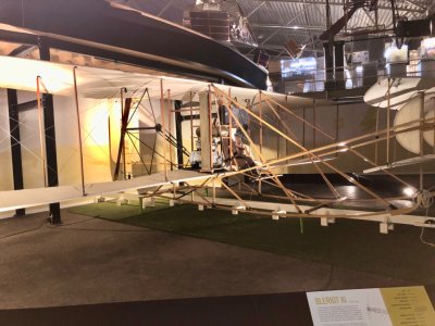
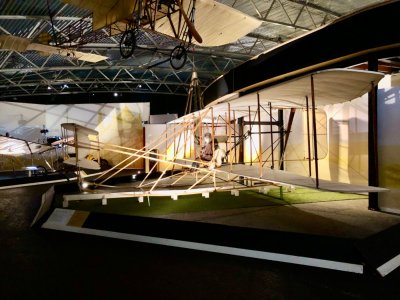
From what I have read there were 3 versions of the Flyer. In the third revision after they had ironed out quite a few problems they were able to change the controls to accommodate a sitting pilot and a passenger. This must be a replica of the 3rd version. It would seem during the first two versions laying down was their effort to reduce drag.Today I visited the Aviodrome in relation to my research for information on my little Kolibrie project.
While there, I stumbled upon a replica of the Wright Flyer (where the pilot is sitting upright, instead of in the prone position).
Here a few pics of the replica:
View attachment 471620
View attachment 471621
Wow, Daniel building an airplane! I love it!
Great work so far!
Great work so far!
Thank you, Dean. Wow it is great to see you back posting on the forum my friend!Wow, Daniel building an airplane! I love it!
Great work so far!
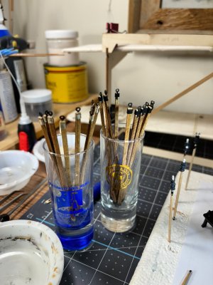
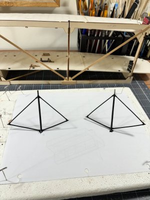
Good Friday morning all. I have been making slow but steady progress on various areas of the Flyer. After lashing all 36 loop ends to the 18 struts using black rope I discovered the real plane used light tan lashing. So, this is my first official do over (in progress) with tan lashing.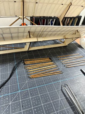
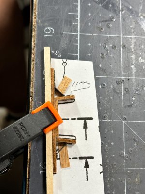
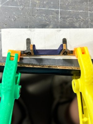
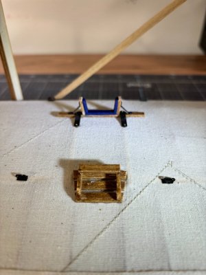
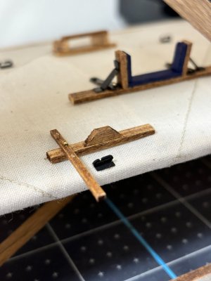
Next are the lower wing pilot accommodations of a footrest/brace. The wig warping cradle that the pilot shifts left and right with his hips for rolling the plane left/right, (fore runner of the ailerons), and the engine control lever and radiator support.
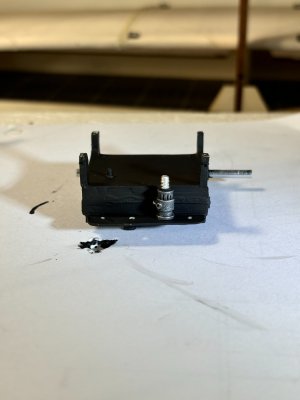
Here I have begun engine assembly with painting and preparation of the propeller support system. This pot metal is so soft, almost lead like you can easily deform it with your fingers, this has its advantages and disadvantages. Per the plans I drilled 4ea 0.7mm ok 0,7mm holes in the feet of the crank case for mounting into the engine support rails. The engine is heavy enough that just CA probably would not be strong enough. Dry Docks 0.6mm nails work perfect with this. Once I set it in place I just drill further into the frame then glue it all down.
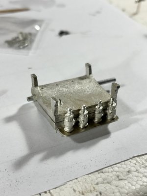
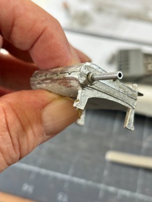
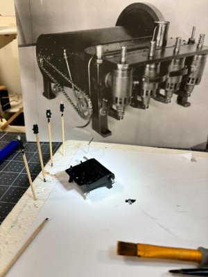
This last photo has a picture of the actual engine and is a great help along with the instructions during assembly. I'm hoping to dry brush the 4 ignition heads to look like the picture.
I am so fortunate the CA glue works well on the fabric and into the wood underneath.
Thats it for now, till next time have a great time!


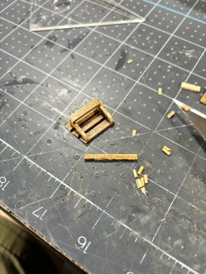
Next are the lower wing pilot accommodations of a footrest/brace. The wig warping cradle that the pilot shifts left and right with his hips for rolling the plane left/right, (fore runner of the ailerons), and the engine control lever and radiator support.


Here I have begun engine assembly with painting and preparation of the propeller support system. This pot metal is so soft, almost lead like you can easily deform it with your fingers, this has its advantages and disadvantages. Per the plans I drilled 4ea 0.7mm ok 0,7mm holes in the feet of the crank case for mounting into the engine support rails. The engine is heavy enough that just CA probably would not be strong enough. Dry Docks 0.6mm nails work perfect with this. Once I set it in place I just drill further into the frame then glue it all down.


This last photo has a picture of the actual engine and is a great help along with the instructions during assembly. I'm hoping to dry brush the 4 ignition heads to look like the picture.

I am so fortunate the CA glue works well on the fabric and into the wood underneath.
Thats it for now, till next time have a great time!
Great details Daniel! I love it!Good Friday morning all. I have been making slow but steady progress on various areas of the Flyer. After lashing all 36 loop ends to the 18 struts using black rope I discovered the real plane used light tan lashing. So, this is my first official do over (in progress) with tan lashing.View attachment 472037View attachment 472038
Next are the lower wing pilot accommodations of a footrest/brace. The wig warping cradle that the pilot shifts left and right with his hips for rolling the plane left/right, (fore runner of the ailerons), and the engine control lever and radiator support.
View attachment 472039View attachment 472040View attachment 472041View attachment 472042View attachment 472043
Here I have begun engine assembly with painting and preparation of the propeller support system. This pot metal is so soft, almost lead like you can easily deform it with your fingers, this has its advantages and disadvantages. Per the plans I drilled 4ea 0.7mm ok 0,7mm holes in the feet of the crank case for mounting into the engine support rails. The engine is heavy enough that just CA probably would not be strong enough. Dry Docks 0.6mm nails work perfect with this. Once I set it in place I just drill further into the frame then glue it all down.
View attachment 472046View attachment 472047View attachment 472048
This last photo has a picture of the actual engine and is a great help along with the instructions during assembly. I'm hoping to dry brush the 4 ignition heads to look like the picture.
View attachment 472049
I am so fortunate the CA glue works well on the fabric and into the wood underneath.
Thats it for now, till next time have a great time!
That looks really good to me!Thanks Dean.
I'm not a dry brush pro like you but I think I got this one close.
View attachment 472060
Nice pictures of the building process and the details, Daniel. It looks ‘complex in it’s simplicity’.Good Friday morning all. I have been making slow but steady progress on various areas of the Flyer. After lashing all 36 loop ends to the 18 struts using black rope I discovered the real plane used light tan lashing. So, this is my first official do over (in progress) with tan lashing.View attachment 472037View attachment 472038
Next are the lower wing pilot accommodations of a footrest/brace. The wig warping cradle that the pilot shifts left and right with his hips for rolling the plane left/right, (fore runner of the ailerons), and the engine control lever and radiator support.
View attachment 472039View attachment 472040View attachment 472041View attachment 472042View attachment 472043
Here I have begun engine assembly with painting and preparation of the propeller support system. This pot metal is so soft, almost lead like you can easily deform it with your fingers, this has its advantages and disadvantages. Per the plans I drilled 4ea 0.7mm ok 0,7mm holes in the feet of the crank case for mounting into the engine support rails. The engine is heavy enough that just CA probably would not be strong enough. Dry Docks 0.6mm nails work perfect with this. Once I set it in place I just drill further into the frame then glue it all down.
View attachment 472046View attachment 472047View attachment 472048
This last photo has a picture of the actual engine and is a great help along with the instructions during assembly. I'm hoping to dry brush the 4 ignition heads to look like the picture.
View attachment 472049
I am so fortunate the CA glue works well on the fabric and into the wood underneath.
Thats it for now, till next time have a great time!
Regards, Peter


