Thanks Peter, that is a good description for this project.It looks ‘complex in it’s simplicity’.
-

Win a Free Custom Engraved Brass Coin!!!
As a way to introduce our brass coins to the community, we will raffle off a free coin during the month of August. Follow link ABOVE for instructions for entering.
-

PRE-ORDER SHIPS IN SCALE TODAY!
The beloved Ships in Scale Magazine is back and charting a new course for 2026!
Discover new skills, new techniques, and new inspirations in every issue.
NOTE THAT OUR FIRST ISSUE WILL BE JAN/FEB 2026
- Home
- Forums
- Ships of Scale Build Logs
- Super Detailing Static Models / Other Genres
- Historical Trailways, Guns, Aircraft, and Cars
You are using an out of date browser. It may not display this or other websites correctly.
You should upgrade or use an alternative browser.
You should upgrade or use an alternative browser.
Hello all, I wanted to show progress on the engine assembly. One of the Wright brothers' employees named Charles Tayler designed and hand crafted a horizontal cast aluminum block with 4 cylinders. The engine weighed 170 pounds and produced 12 HP. So far I have installed 4 ignition heads powered by a magneto (no spark plugs). They used a camshaft system to deliver electrical charges to the ingnition heads. Installed the ignition cam and the exhaust cam and intake valve stems. You can also see the rocker arms and their construction.
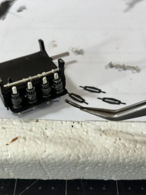
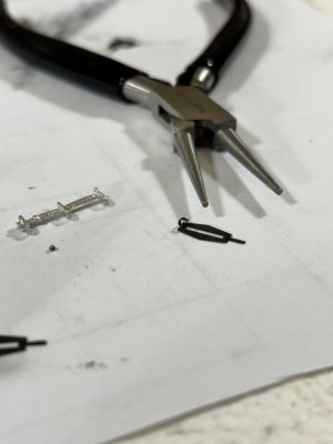
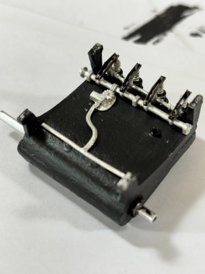
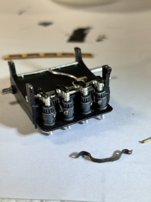
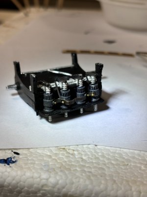
Next you can see the ignition cam followers and the ignition terminal strip. Per the instructions I hand bent the strip to match the little port holes, drilled into the port holes and attached the strip glue them in place.
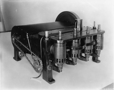
Again, here is a photo of the look I am after.
Hope you all enjoy, till next time have a great day.


Next you can see the ignition cam followers and the ignition terminal strip. Per the instructions I hand bent the strip to match the little port holes, drilled into the port holes and attached the strip glue them in place.


Again, here is a photo of the look I am after.

Hope you all enjoy, till next time have a great day.
Looking good Daniel.Hello all, I wanted to show progress on the engine assembly. One of the Wright brothers' employees named Charles Tayler designed and hand crafted a horizontal cast aluminum block with 4 cylinders. The engine weighed 170 pounds and produced 12 HP. So far I have installed 4 ignition heads powered by a magneto (no spark plugs). They used a camshaft system to deliver electrical charges to the ingnition heads. Installed the ignition cam and the exhaust cam and intake valve stems. You can also see the rocker arms and their construction.
View attachment 472466View attachment 472467View attachment 472468
Next you can see the ignition cam followers and the ignition terminal strip. Per the instructions I hand bent the strip to match the little port holes, drilled into the port holes and attached the strip glue them in place.
View attachment 472469View attachment 472470
Again, here is a photo of the look I am after.
View attachment 472471
Hope you all enjoy, till next time have a great day.
Good afternoon, all, just about a week ago I started concentrating on the Flyers engine and today installed it in place. If you look closely at the engine feet you can see where I drilled holes and inserted a small nail with CA so it's very secure.
For positioning I temporarily set the propellor stanchions since they really dictate the engines' precise location, then ran a chain between the two supports letting it droop down over the flywheel oiler where there are two nibs that need to line with the propellor shaft hubs. Moving the oiler under the chain lines everything up.
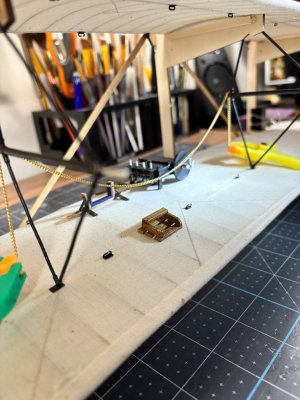
Next, I built out the magneto and set it on its wood supports being careful to place the friction wheel up against the flywheel. Then finally installed the wiring from the mag to the engine. The ground going to the block and the hot end to the first ignition head.
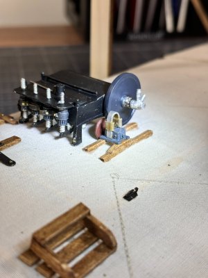
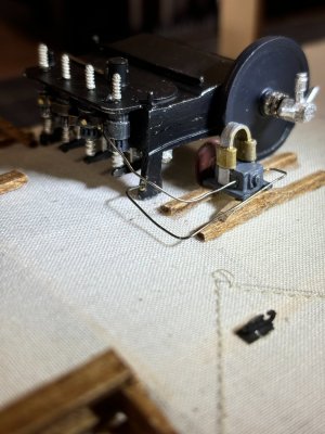
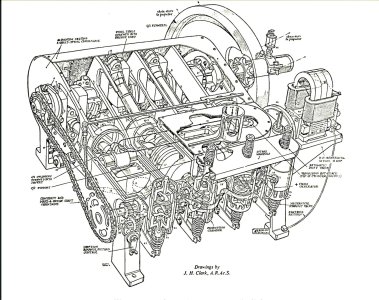
Last I have included a detailed cut away drawing I found on the Flyers web site, it's very cool.
Now I can resume building on the air frame and at least one more session my electromechanical reciprocating coupling device for some needed seams on the rest of the kinard and rudder coverings.
Thanks for checking in.
For positioning I temporarily set the propellor stanchions since they really dictate the engines' precise location, then ran a chain between the two supports letting it droop down over the flywheel oiler where there are two nibs that need to line with the propellor shaft hubs. Moving the oiler under the chain lines everything up.

Next, I built out the magneto and set it on its wood supports being careful to place the friction wheel up against the flywheel. Then finally installed the wiring from the mag to the engine. The ground going to the block and the hot end to the first ignition head.


Last I have included a detailed cut away drawing I found on the Flyers web site, it's very cool.

Now I can resume building on the air frame and at least one more session my electromechanical reciprocating coupling device
Thanks for checking in.
Hello Smithy, welcome aboard. I have let more than a few curse words fly during this build due to my clumsiness.Fragile is definitely the first word that came to my mind. I would be nervous just bringing my clumsy self into the same room as a model like this.
You seem well able to cope with it though. I look forward to seeing it completed.
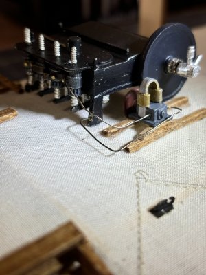
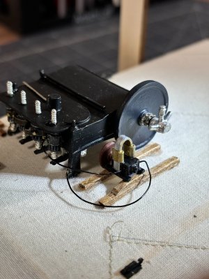
Definite improvement!I felt the need to make an adjustment to the wiring on the Flyers engine. Looking at my macro shots highlights a lot of scuffs and dust. I think what follows better represents the wiring, see what you think. I also darkened the body of the magneto.
Old way New way
View attachment 472898 View attachment 472899
Hi Shota! Glad you found my build.my dear friend Daniel
I missed your amazing progress , well done
As far as the engine plumbing goes, I neglected to connect a lower radiator hose to the provided nipple coming off the bottom side of the crankcase, naturally after I had glued and nailed down the block thus severely limiting access. I wanted to show my solution to this plumbing problem. First, I made a wire template with the necessary bends and lengths, then with the largest brass tubing I had, fashioned the piece that would get me out from under the crankcase. The rubber tubing provided is too big in diameter, so I was able to slide it into some brass tubing, very briefly hit with my torch and it shrunk like a glove onto the tubing. glueing the fabricated piece into the tube and ready for installation.
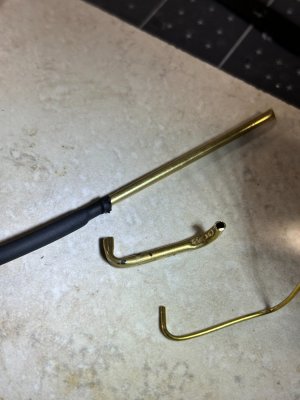
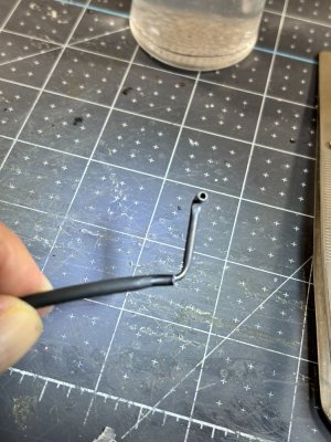
After some careful insertion (winding around, holding with helper tools) was able to fit the open end onto the protruding nub and glue in place. WHEW!! didn't break any of the delicate rocker arms or other underside fittings.
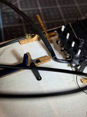
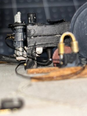
I got lucky on this oversight.
For the rest of this build I will have to have the top wing in place which cuts way down on easy access so here we go.
Thanks for looking in.


After some careful insertion (winding around, holding with helper tools) was able to fit the open end onto the protruding nub and glue in place. WHEW!! didn't break any of the delicate rocker arms or other underside fittings.


I got lucky on this oversight.
For the rest of this build I will have to have the top wing in place which cuts way down on easy access so here we go.
Thanks for looking in.
A really exceptional modeler would get a clamp on that hoseAs far as the engine plumbing goes, I neglected to connect a lower radiator hose to the provided nipple coming off the bottom side of the crankcase, naturally after I had glued and nailed down the block thus severely limiting access. I wanted to show my solution to this plumbing problem. First, I made a wire template with the necessary bends and lengths, then with the largest brass tubing I had, fashioned the piece that would get me out from under the crankcase. The rubber tubing provided is too big in diameter, so I was able to slide it into some brass tubing, very briefly hit with my torch and it shrunk like a glove onto the tubing. glueing the fabricated piece into the tube and ready for installation.
View attachment 473508View attachment 473509
After some careful insertion (winding around, holding with helper tools) was able to fit the open end onto the protruding nub and glue in place. WHEW!! didn't break any of the delicate rocker arms or other underside fittings.
View attachment 473512View attachment 473513
I got lucky on this oversight.
For the rest of this build I will have to have the top wing in place which cuts way down on easy access so here we go.
Thanks for looking in.
Kurt Konrath
Kurt Konrath
A small flat string would work good for makeshift clamp on this install, or paint of silver if that talented like Doc K with tiny brushes.
A really exceptional modeler would get a clamp on that hose
I do appreciate the suggestions regarding the use of hose clamps however it appears that the pressures involved did not require their use as depicted in this photo.A small flat string would work good for makeshift clamp on this install, or paint of silver if that talented like Doc K with tiny brushes.
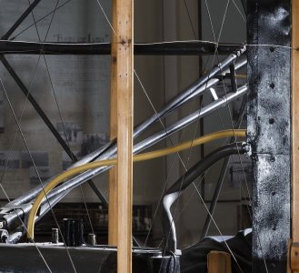
Oh, snap! A triumph of research over tongue-in-cheek… 

I wouldn’t trust the rebuild. They probably forgot to install the hose before the engine was put into its final place.I do appreciate the suggestions regarding the use of hose clamps however it appears that the pressures involved did not require their use as depicted in this photo.
View attachment 473603
Yea, they wouldn't want me near it.They probably forgot to install the hose before the engine was put into its final place.


- Joined
- Sep 3, 2021
- Messages
- 5,190
- Points
- 738

A very convincing representation of that aero engine, taking your time to get the finish right is paying dividends.Hello all, I wanted to show progress on the engine assembly. One of the Wright brothers' employees named Charles Tayler designed and hand crafted a horizontal cast aluminum block with 4 cylinders. The engine weighed 170 pounds and produced 12 HP. So far I have installed 4 ignition heads powered by a magneto (no spark plugs). They used a camshaft system to deliver electrical charges to the ingnition heads. Installed the ignition cam and the exhaust cam and intake valve stems. You can also see the rocker arms and their construction.
View attachment 472466View attachment 472467View attachment 472468
Next you can see the ignition cam followers and the ignition terminal strip. Per the instructions I hand bent the strip to match the little port holes, drilled into the port holes and attached the strip glue them in place.
View attachment 472469View attachment 472470
Again, here is a photo of the look I am after.
View attachment 472471
Hope you all enjoy, till next time have a great day.
- Joined
- Sep 3, 2021
- Messages
- 5,190
- Points
- 738

I started using this very same method to locate some of my parts and assemblies. Great minds...If you look closely at the engine feet you can see where I drilled holes and inserted a small nail with CA so it's very secure.
Thank you Johan.A very convincing representation of that aero engine, taking your time to get the finish right is paying dividends.


