Clever solution...
-

Win a Free Custom Engraved Brass Coin!!!
As a way to introduce our brass coins to the community, we will raffle off a free coin during the month of August. Follow link ABOVE for instructions for entering.
-

PRE-ORDER SHIPS IN SCALE TODAY!
The beloved Ships in Scale Magazine is back and charting a new course for 2026!
Discover new skills, new techniques, and new inspirations in every issue.
NOTE THAT OUR FIRST ISSUE WILL BE JAN/FEB 2026
- Home
- Forums
- Ships of Scale Group Builds and Projects
- Bluenose PoF Group Build
- Bluenose Group Build Logs
You are using an out of date browser. It may not display this or other websites correctly.
You should upgrade or use an alternative browser.
You should upgrade or use an alternative browser.
- Joined
- Sep 3, 2021
- Messages
- 5,199
- Points
- 738

Thanks.Clever solution...
- Joined
- Sep 3, 2021
- Messages
- 5,199
- Points
- 738

Took me a while to figure it out though; I was too focused on bending instead of looking for other options..Clever solution...
Last edited:
Yup. I've burned half a day failing at something only to wake up the next morning with a 10 minute solution...Took me a while to figure it out though; I was just too focused on bending instead of looking for other options..
- Joined
- Sep 3, 2021
- Messages
- 5,199
- Points
- 738

This is just too familiar....Yup. I've burned half a day failing at something only to wake up the next morning with a 10 minute solution...
I agree with Paul. Clever thinking and well made. And no burned fingers during the heat bending.After completing the planking of the forward- and quarterdecks, I shifted my attention to the railings.
After dry fitting, where I found deviations between the upper contours of my hull and the pre-cut YQ railing parts, I started the painting of the railing parts, since, once installed, some of the surfaces to be painted are not really accessible. The paining of the parts gave me ample time to consider my options on how to install the railings. For now I'm leaning towards drilling holes through the railings into the stanchions and to use some toothpicks to positively fix the railings to the hull. The first railing to be installed consists of seven parts. I will not make a sub assembly of these parts; too much adhesive to apply at once, so instead I'll install them one at a time.
Luckily for me the paint is still drying, but the moment draws near I have to use my drills...
One of the issues I encountered with part 149, part of the monkey rail, see picture below, is that even though I let the part soak and used a heat source the facilitate bending, the first thing happening to me was that the railing part broke...
View attachment 331708
Also, the radius in the picture appears to be quite large, but when looking at the drawings, the radius should be rather small. I did some sketching, where I found that the radius should be around 3,5mm/0,14".
The picture below shows my interpretation (shaded) of the monkey rail at the stern. As you can see, a larger radius is not feasible, the railing would creep from under the horizontal part of the rail; not acceptable.
View attachment 331709
Based on the picture above, I decided to make two separate corner pieces from a piece of scrap with the correct thickness, see picture below.
View attachment 331712
After drilling, sawing and trimming, I am now close to what might become an acceptable monkey rail. The constriction at the outer ends of the left part will be trimmed at a later stage:
View attachment 331714
Regards, Peter
- Joined
- Sep 3, 2021
- Messages
- 5,199
- Points
- 738

Thanks Peter!I agree with Paul. Clever thinking and well made. And no burned fingers during the heat bending.
Regards, Peter
And indeed, no burnt fingers...
- Joined
- Oct 28, 2018
- Messages
- 760
- Points
- 403

Nice solution indeed Johan
Good to know that my jigsaw machine could help you with this
Greeting
Henk
Good to know that my jigsaw machine could help you with this
Greeting
Henk
- Joined
- Sep 3, 2021
- Messages
- 5,199
- Points
- 738

Yep, your sawing machine was a great piece of equipment to use, even for these tiny parts.Nice solution indeed Johan
Good to know that my jigsaw machine could help you with this
Greeting
Henk

- Joined
- Sep 3, 2021
- Messages
- 5,199
- Points
- 738

After dragging my feet for awhile, I could no longer postpone the installation of the bulwarks. The reason for delaying this step was that I had no idea how to position the partsforming the bulwarks onto the hull in a robust manner.
One has to consider that free passage of the later to be installed chainplates has to be maintained, the stanchions are nicely covered by the bulwarks and that the offset of the outer edge of the bulwarks, relative planking of the hull, is similar over the length of the hull.
After much reading and tinkering with the bulwark parts I came to the following process;
- Use a 0,5mm/0.020" thin strip to simulate the chainplates and insert that through one of the chainplates holes, see also @Peter Voogt's build, it's his idea, I think.
- Align the inner edge of the bulwark at the fwd and aft end of the parts with the inner edges of the stanchions.
- Drill holes 0,8mm/0,037" through and through and use some small nails of matching diameters, together with the chain plate simulation, to fix the position of the bulwark.
- Determine two other locations to drill fixation holes, depending on the deviations between the pre-cut bulwark parts and the hull (which is, of course, perfectly build...)
- After insertion another two nails, check the overall dry fit of the bulwark. Not that there's much you can do about it after drilling holes...
- Once satisfied, apply adhesive, reposition the bulwark and insert toothpicks through the earlier drilled holes and apply some pressure to ensure proper seating of the bulwark gains the upper edge of the first plank.
- Clean up any excessive adhesive and after allowing the adhesive to cure, cut off the toothpicks and there it is, a bulwark installed.
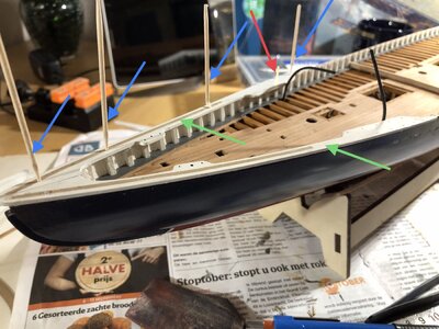
Below a picture of the first two bulwarks installed. The bulwark on the right hand/lower side is ready for touch-up, the left hand/upper side (as seen in the picture) bulwark is waiting for the adhesive to cure.
The red arrow indicates the fake chainplate, ensuring the bulwark doesn't move inwards, the blue toothpicks ensure robust retention of the position of the bulwark on the first plank. The green arrows indicate the bulwarks themselves.

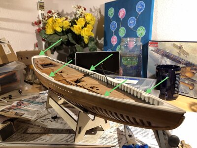
The following picture shows, see green arrows, five of the bulwarks installed.
Still two to follow. Apparently I build my BN about 4mm/0,16" too short; I need to shorten the last two bulwarks by just that amount.

One has to consider that free passage of the later to be installed chainplates has to be maintained, the stanchions are nicely covered by the bulwarks and that the offset of the outer edge of the bulwarks, relative planking of the hull, is similar over the length of the hull.
After much reading and tinkering with the bulwark parts I came to the following process;
- Use a 0,5mm/0.020" thin strip to simulate the chainplates and insert that through one of the chainplates holes, see also @Peter Voogt's build, it's his idea, I think.
- Align the inner edge of the bulwark at the fwd and aft end of the parts with the inner edges of the stanchions.
- Drill holes 0,8mm/0,037" through and through and use some small nails of matching diameters, together with the chain plate simulation, to fix the position of the bulwark.
- Determine two other locations to drill fixation holes, depending on the deviations between the pre-cut bulwark parts and the hull (which is, of course, perfectly build...)
- After insertion another two nails, check the overall dry fit of the bulwark. Not that there's much you can do about it after drilling holes...
- Once satisfied, apply adhesive, reposition the bulwark and insert toothpicks through the earlier drilled holes and apply some pressure to ensure proper seating of the bulwark gains the upper edge of the first plank.
- Clean up any excessive adhesive and after allowing the adhesive to cure, cut off the toothpicks and there it is, a bulwark installed.
Below a picture of the first two bulwarks installed. The bulwark on the right hand/lower side is ready for touch-up, the left hand/upper side (as seen in the picture) bulwark is waiting for the adhesive to cure.
The red arrow indicates the fake chainplate, ensuring the bulwark doesn't move inwards, the blue toothpicks ensure robust retention of the position of the bulwark on the first plank. The green arrows indicate the bulwarks themselves.

The following picture shows, see green arrows, five of the bulwarks installed.
Still two to follow. Apparently I build my BN about 4mm/0,16" too short; I need to shorten the last two bulwarks by just that amount.

Good thinking and making a plan is for this part necessary. And you did it well, Johan.After dragging my feet for awhile, I could no longer postpone the installation of the bulwarks. The reason for delaying this step was that I had no idea how to position the partsforming the bulwarks onto the hull in a robust manner.
One has to consider that free passage of the later to be installed chainplates has to be maintained, the stanchions are nicely covered by the bulwarks and that the offset of the outer edge of the bulwarks, relative planking of the hull, is similar over the length of the hull.
After much reading and tinkering with the bulwark parts I came to the following process;
- Use a 0,5mm/0.020" thin strip to simulate the chainplates and insert that through one of the chainplates holes, see also @Peter Voogt's build, it's his idea, I think.
- Align the inner edge of the bulwark at the fwd and aft end of the parts with the inner edges of the stanchions.
- Drill holes 0,8mm/0,037" through and through and use some small nails of matching diameters, together with the chain plate simulation, to fix the position of the bulwark.
- Determine two other locations to drill fixation holes, depending on the deviations between the pre-cut bulwark parts and the hull (which is, of course, perfectly build...)
- After insertion another two nails, check the overall dry fit of the bulwark. Not that there's much you can do about it after drilling holes...
- Once satisfied, apply adhesive, reposition the bulwark and insert toothpicks through the earlier drilled holes and apply some pressure to ensure proper seating of the bulwark gains the upper edge of the first plank.
- Clean up any excessive adhesive and after allowing the adhesive to cure, cut off the toothpicks and there it is, a bulwark installed.
Below a picture of the first two bulwarks installed. The bulwark on the right hand/lower side is ready for touch-up, the left hand/upper side (as seen in the picture) bulwark is waiting for the adhesive to cure.
The red arrow indicates the fake chainplate, ensuring the bulwark doesn't move inwards, the blue toothpicks ensure robust retention of the position of the bulwark on the first plank. The green arrows indicate the bulwarks themselves.
View attachment 331965
The following picture shows, see green arrows, five of the bulwarks installed.
Still two to follow. Apparently I build my BN about 4mm/0,16" too short; I need to shorten the last two bulwarks by just that amount.
View attachment 331966
Adjusting the last 2 parts is more easy then adjusting the hull to those parts.

I also had to adjust them in length. That 4mm is partly depending how far you have let the planking extend at the bow and stern. And the complex transom can also make a difference.
I have every confidence that this section will be neat and tidy.
Then up to the Main- Monkey- and Buffalo rail. I see that you have left some part free of paint to let the glue works. Also here: good thinking!
Regard, Peter
- Joined
- Sep 3, 2021
- Messages
- 5,199
- Points
- 738

Thanks for your compliments, Peter.Good thinking and making a plan is for this part necessary. And you did it well, Johan.
Adjusting the last 2 parts is more easy then adjusting the hull to those parts.
I also had to adjust them in length. That 4mm is partly depending how far you have let the planking extend at the bow and stern. And the complex transom can also make a difference.
I have every confidence that this section will be neat and tidy.
Then up to the Main- Monkey- and Buffalo rail. I see that you have left some part free of paint to let the glue works. Also here: good thinking!
Regard, Peter
The (over)thinking and planning is probably a left over from another life in the aircraft industry, although this tendency can be observed all over the SOS-board...
And yes, there's an awfull lot of planning to be done for the bulwarks and monkey rails; basically all parts need to have paint applied, prior to installation, since after that there's little to no access to those surfaces, plus you still have to have unpainted surfaces to apply your adhesive to for the installation of the other parts.
Luckily others (
- Joined
- Sep 3, 2021
- Messages
- 5,199
- Points
- 738

Adjusting the last 2 parts is more easy then adjusting the hull to those parts.
 Good heavens, adjusting the hull...
Beautiful work Johan. Yes, overthinking is available in abundance on this forum. And just when we think we have it all just right we look again and exclaim: "what was I thinking?"
- Joined
- Sep 4, 2022
- Messages
- 127
- Points
- 113

Roger that!The (over)thinking and planning is probably a left over from another life in the aircraft industry, although this tendency can be observed all over the SOS-board...

- Joined
- Jan 9, 2020
- Messages
- 10,566
- Points
- 938

Very meticulous and exact planning, Johan which will stand you in good stead with the steps to come. But then - this what I have come to expect of you - I know that the final results will justify all the time spent contemplating!
- Joined
- Sep 3, 2021
- Messages
- 5,199
- Points
- 738

Thanks Heinrich!Very meticulous and exact planning, Johan which will stand you in good stead with the steps to come. But then - this what I have come to expect of you - I know that the final results will justify all the time spent contemplating!
I always try to plan ahead and envision the end result. But all too frequently I'm pulling my hairs and sigh: "what was I thinking" (@dockattner, thanks Paul), followed by "apparently not".
There's this suspicion I have that every kit being build requires planning ahead and this Bluenose kit is no exception to the rule. And given that the building instructions are very basic, one simply has to use the available grey matter.
Were you able to enjoy another day on the water?
- Joined
- Sep 3, 2021
- Messages
- 5,199
- Points
- 738

The first railings are in place, the process I used and described earlier worked like a charm.
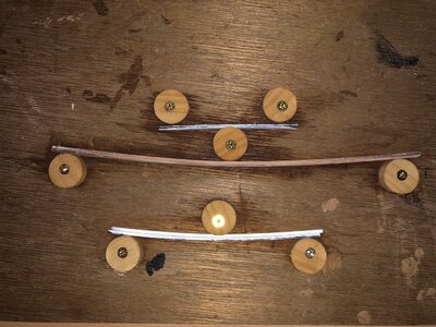
Now the vertical parts of the monkey rail are work-in-progress. The vertical parts follow the contours of the hull, meaning they have a curvature. When bonding the parts to the first railing parts, I want to have the least possible tension. That's why I preform the parts to match the desired curvature. Based on the YQ drawings, I determined the maximum deviation between a straight line, drawn between the two extreme ends of the parts and measuring the maximum distance between the chord and the curvature.
These dimensions were transferred to a board, where I used discs from a broomstick with some screws, securing the discus to the board. I drilled a slightly off-center hole, in order to be able to adjust the curvature. Then I placed the pre-soaked parts in this set-up and let the parts sit for the night.
A first dry-fit this morning indicated some more tweaking was in order, but so far I'm pleased with the results.
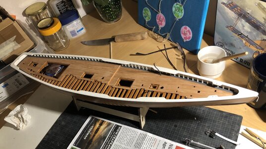
First seven bulwark parts installed:

The bending set-up:

Now the vertical parts of the monkey rail are work-in-progress. The vertical parts follow the contours of the hull, meaning they have a curvature. When bonding the parts to the first railing parts, I want to have the least possible tension. That's why I preform the parts to match the desired curvature. Based on the YQ drawings, I determined the maximum deviation between a straight line, drawn between the two extreme ends of the parts and measuring the maximum distance between the chord and the curvature.
These dimensions were transferred to a board, where I used discs from a broomstick with some screws, securing the discus to the board. I drilled a slightly off-center hole, in order to be able to adjust the curvature. Then I placed the pre-soaked parts in this set-up and let the parts sit for the night.
A first dry-fit this morning indicated some more tweaking was in order, but so far I'm pleased with the results.
First seven bulwark parts installed:

The bending set-up:

Last edited:
The base for the railing looks good.

Regards, Peter
And again: good thinking, Johan.I used discs from a broomstick with some screws, securing the discus to the board. I drilled a slightly off-center hole, in order to be able to adjust the curvature. Then I placed the pre-soaked parts in this set-up and let the parts sit for the night.
Regards, Peter
- Joined
- Sep 4, 2022
- Messages
- 127
- Points
- 113

Nice bending jig that I likely will adapt for myself when I get needing one. Your pic does give me the idea of one tweak that I'll make when I do it; I'll drill the broom plugs off-center making them adjustable " cam lobes" for more or less bend tension. Thanks for showing this.The first railings are in place, the process I used and described earlier worked like a charm.
Now the vertical parts of the monkey rail are work-in-progress. The vertical parts follow the contours of the hull, meaning they have a curvature. When bonding the parts to the first railing parts, I want to have the least possible tension. That's why I preform the parts to match the desired curvature. Based on the YQ drawings, I determined the maximum deviation between a straight line, drawn between the two extreme ends of the parts and measuring the maximum distance between the chord and the curvature.
These dimensions were transferred to a board, where I used discs from a broomstick with some screws, securing the discus to the board. I drilled a slightly off-center hole, in order to be able to adjust the curvature. Then I placed the pre-soaked parts in this set-up and let the parts sit for the night.
A first dry-fit this morning indicated some more tweaking was in order, but so far I'm pleased with the results.
First seven bulwark parts installed:
View attachment 332252
The bending set-up:
View attachment 332251
alf in Iowa
EDIT: Aw gimminy my head must've been up and locked (old aviation talk) when I was reading. You already mentioned the off center cam lobe thing. I'm sorry (hang head down)
Last edited:

