YUANQING BLUENOSE - Heinrich

On my keel assembly - and I have no idea if this is peculiar to the way that I built the keel - the unbeveled part of Part #18 does not lie level with the sternpost -
Heinrich,
Have you added the "cheek" layers at the sternpost--part #22 on either side, which lies over part #15--this should fill out the depth of the sternpost and raise the level to equal that of the unbeveled part of #18. See the image below.20201229_224056.jpg
 
Last edited:
Hello Everyone
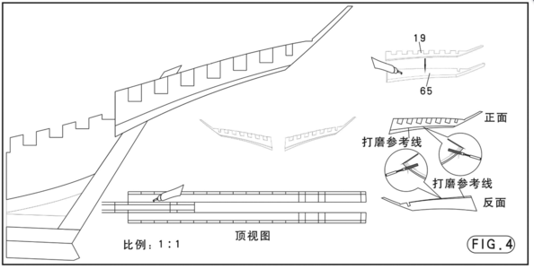
I want to share my "modification" that I mentioned last night. As you will recall, I explained how Parts #19 and #65 are combined (by gluing together) and then beveled.

View attachment 202508

Here you can see how the #19/65 combination is glued to the keel - one on either side. For this, YuanQing has provided us with with a 1:1-scale drawing. This allows you to place the keel exactly over the drawing and then align the combined Part #19/65 in its correct - position. No problem here! :)

But now let's take a look at the picture below.

View attachment 202507

On my keel assembly - and I have no idea if this is peculiar to the way that I built the keel - the unbeveled part of Part #18 does not lie level with the sternpost - it is slightly higher (it is the same on the other side). This means that my combination Part #19/65 will not lie flush with the unbeveled section of Part #18 and the sternpost. My solution was as follows:

View attachment 202509

I simply cut out the piece (as is indicated in yellow) on the backing sheet which housed Part #18 making sure that I followed the exact lines of Part #18.

View attachment 202510

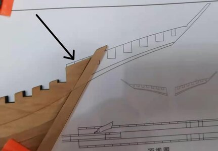
It is better illustrated on this drawing where the two sections that I cut out are marked in red and pointed out by the bold, black arrow. These I then glued onto the sternpost and once the glue had dried I cut off the overhang at the back.

View attachment 202511

The inserted piece on the Port Side.

View attachment 202512

And on the starboard side.

Now everything is flush and ready to accommodate our combination part #19/65. As mentioned before, I don't know if you will be affected by the same issue, but if you are, you know what you can do.

Kind regards - Heinrich
Good thinking Heinrich.Okay
And a nice solution.

And Eric gives the hint. Thumbs-Up
Nice acting as a team!

Regards, Peter
 
Last edited:
Eric

You beauty. NO I HAVE NOT !!!!!:eek::mad:RedfaceRedfaceRedface
Heinrich,
Have you added the "cheek" layers at the sternpost--part #22 on either side, which lies over part #15--this should fill out the depth of the sternpost and raise the level to equal that of the unbeveled part of #18. See the image below.View attachment 202536
 
@Pathfinder65 Jan I did do the fine work in daylight and was very proud of what I have done - until I read from Eric that it was completely unnecessary. It could have been accomplished - and CORRECTLY accomplished in 5 minutes. And all, because I did not read the plans properly!
 
Hello Everyone

I want to share my "modification" that I mentioned last night. As you will recall, I explained how Parts #19 and #65 are combined (by gluing together) and then beveled.

View attachment 202508

Here you can see how the #19/65 combination is glued to the keel - one on either side. For this, YuanQing has provided us with with a 1:1-scale drawing. This allows you to place the keel exactly over the drawing and then align the combined Part #19/65 in its correct - position. No problem here! :)

But now let's take a look at the picture below.

View attachment 202507

On my keel assembly - and I have no idea if this is peculiar to the way that I built the keel - the unbeveled part of Part #18 does not lie level with the sternpost - it is slightly higher (it is the same on the other side). This means that my combination Part #19/65 will not lie flush with the unbeveled section of Part #18 and the sternpost. My solution was as follows:

View attachment 202509

I simply cut out the piece (as is indicated in yellow) on the backing sheet which housed Part #18 making sure that I followed the exact lines of Part #18.

View attachment 202510

It is better illustrated on this drawing where the two sections that I cut out are marked in red and pointed out by the bold, black arrow. These I then glued onto the sternpost and once the glue had dried I cut off the overhang at the back.

View attachment 202511

The inserted piece on the Port Side.

View attachment 202512

And on the starboard side.

Now everything is flush and ready to accommodate our combination part #19/65. As mentioned before, I don't know if you will be affected by the same issue, but if you are, you know what you can do.

Kind regards - Heinrich
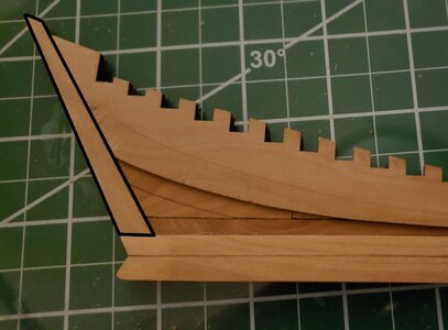
This jig-saw puzzle assembly of small pieces amazes me as to how it was conceived by the model designer with the multitude of laser cut pieces. Being thin planar surfaces though they are not asking for carving/filing to obtain the same shapes from a more thick piece of wood. Fascinating. RIch
 
Just a quick update everyone.

After yesterday's "OOPS" - which I could rescue just in time - it was time to move on to attaching the Combination Parts #19/65 to the keel.

Untitled.png

微信图片_20210101211615.jpg

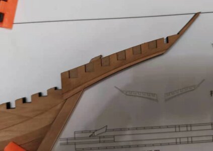
I first clamped the drawing to the building board and after aligning the keel with the drawing, clamped that as well. IAs I was 100% sure that the keel was properly aligned with the drawing, was puzzled by the oddly protruding section at the top (see arrow). A quick check with YuanQing's test builders confirmed that this was indeed correct .

微信图片_20210101211659.jpg

I applied glue to the combination part (thinly) and placed it into position obviously taking great care that all angles were lined up. I did not dare clamp it, for fear of the part shifting under the clamp. I just applied finger pressure and left it for an hour. When I was sure that I had a proper alignment I clamped it for another hour. Then I repeated the process with the other side.

微信图片_20210101211625.jpg

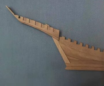
Starboard side completed as well. The alignment of the two parts is PERFECT!

微信图片_20210101211709.jpg

And this is what the keel/transom assembly looks like tonight. Back to making frames tomorrow!
 
Just a quick update everyone.

After yesterday's "OOPS" - which I could rescue just in time - it was time to move on to attaching the Combination Parts #19/65 to the keel.

View attachment 202810

View attachment 202812

I first clamped the drawing to the building board and after aligning the keel with the drawing, clamped that as well. IAs I was 100% sure that the keel was properly aligned with the drawing, was puzzled by the oddly protruding section at the top (see arrow). A quick check with YuanQing's test builders confirmed that this was indeed correct .

View attachment 202813

I applied glue to the combination part (thinly) and placed it into position obviously taking great care that all angles were lined up. I did not dare clamp it, for fear of the part shifting under the clamp. I just applied finger pressure and left it for an hour. When I was sure that I had a proper alignment I clamped it for another hour. Then I repeated the process with the other side.

View attachment 202814

Starboard side completed as well. The alignment of the two parts is PERFECT!

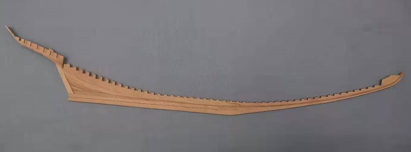
View attachment 202815

And this is what the keel/transom assembly looks like tonight. Back to making frames tomorrow!
And if you ever find yourself in a tight spot late at night in a dark alley it will make for a fine weapon of defense!
 
Don. I owe you an answer on that one. I have not read and translated that far yet. I will comment on those details on Wednesday/Thursday when it is my "weekend".
 
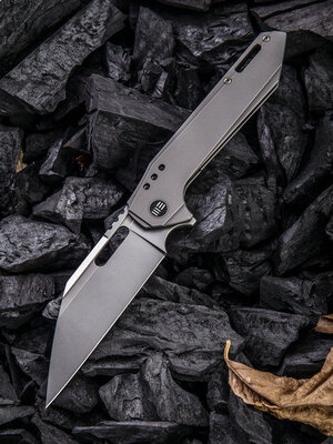
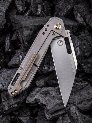
@dockattner @PT-2 Paul & Rich - It is quite funny that you refer to the Bluenose's keel as an edged instrument - you have inadvertently stumbled upon one of my other BIG interests. On its way to me (hopefully) is the Roxi 4 folder - designed by Seth & Terryl Todd from Montana and manufactured by WE KNIVES in Guangdong, China. (6AL4V Titanium Framelock / Ball-raced Flipper mechanism / 4"-long SV35N Wharncliffe blade.

11541SO8-0.jpg
11541R916-3.jpg

And with that little side-distraction out of the way, I thought it best to pay some attention to the instruction manual and the procedure described therein that pertains to the mounting of the frames.

Ass 1.png
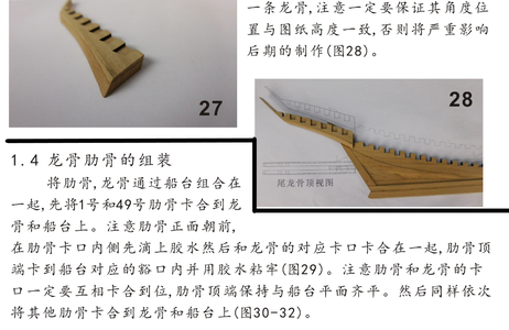
The translation of is of this page and refers to the section in the black-outlined "box".

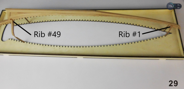
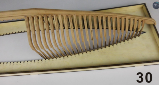
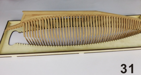
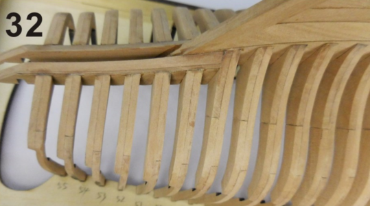
The ribs and keel are assembled via the use of the building jig. First Frame #1 and #49 are glued to the keel. Place the glue in the notch of the frame and then glue it together with the corresponding keel notch (i.e.) Frame #1 will go into the first keel notch. Make sure that this fit is perfect. TAKE THE TIME TO CLEAN/SAND parts accordingly. The top parts of the rib frames are then glued and stuck into the corresponding notches of the building jig. Make sure that the rib frames are completely flush with the top side of the building jig. Follow the same procedure with the other ribs (Figures 29-32).

For the benefit of all, I have supplied you with colour pictures place of the Black-and-White ones of the instruction manual.

Ass 2.png

Ass 3.png

Ass 4.png
Ass 5.png
So you can see there is no mention being made of any upside-down construction techniques (at least not during this phase of the assembly process. However, I will ask YuanQing on Monday about those posted pictures and get them to comment.

Happy Bluenose building guys!
 
Back
Top