HMS Victory Cross Section, POF ,Scale 1:48 by Raymond Deliz

Hello everyone,
I know its been a few days since my last post but I picked up my grandson and had him stay with me in order to spend time together.

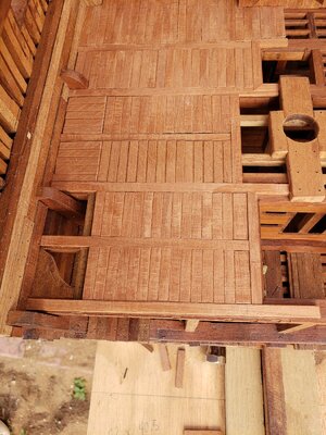
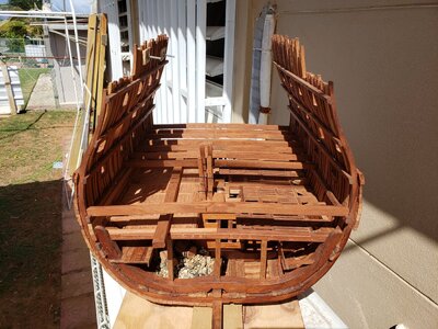
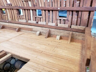
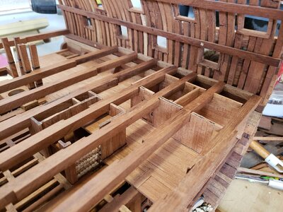
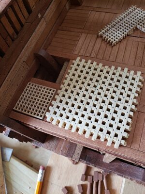
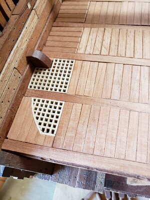
I continued working on the orlop deck, mainly the removable sections over the hold. There are two areas that have not yet been planked due to me having to wIt for grating material I ordered. I did make gratings and know how to make them but my tablesaw is just too damn big and I do not really like the scale of it.

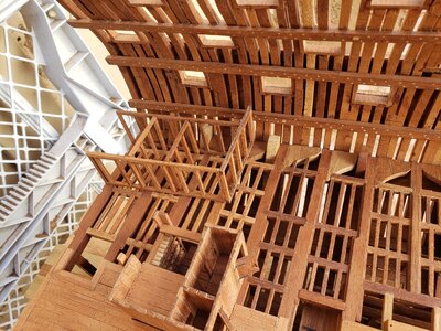
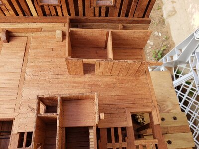
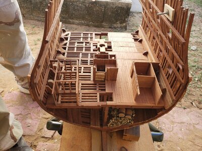
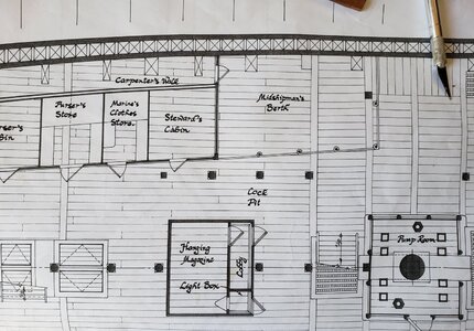
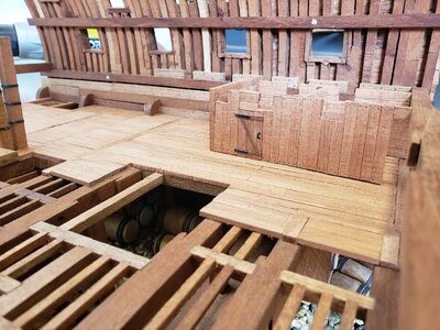
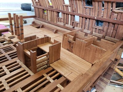
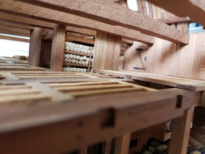
After completing the deck, (up to a point) I looked it over and thought something else was missing. As you all know, I want to keep the port side of my build drastically open to appreciate the construction of the Victory. Since I already did the starboard side captain's and lieutenant's storeroom, I figured how can I add the port side's storeroom without blocking views of the rough construction. It then dawned on me that I could just frame up these rooms so that a person can view it and know that these areas did have something. I was able to frame up the carpenter's walk, the steward's cabin, the Marine's clothes store, and the purser's store.

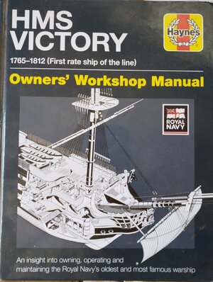
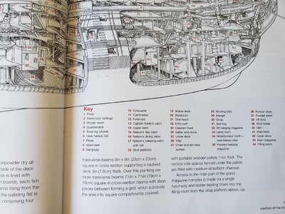
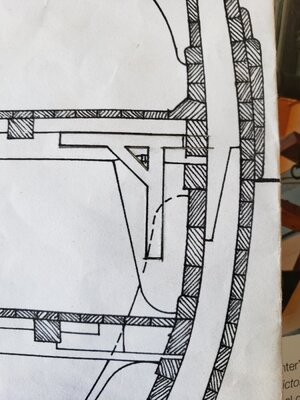
Now that these areas are complete, I am looking at the area in the plans that shows the midshipman's berthing area. Normally, other people have constructed the Victory and have neglected this area and left it open. I have been thinking that I would highlight this area as a roped off section with red rope as a means of establishing the area of the ship where Nelson died. In my Victory plans and AOTS Vicory, this information is not shown. However, the Hayne's HMS Victory Owners' Workshop Manual it is clearly shown in item number 34.20210225_095631.jpg20210225_095638.jpg20210225_095646.jpg20210225_095701.jpg20210225_095713.jpg20210225_103844.jpg20210225_103720.jpg20210225_102737.jpg20210225_103658.jpg20210225_103758.jpg20210225_102813.jpg
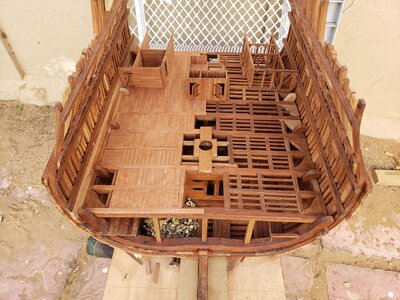
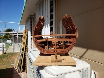
Above are a few photos to show what I have so far and a few photos showing information of the midshipmans berthing area.

Raymond
 
Hello everyone,
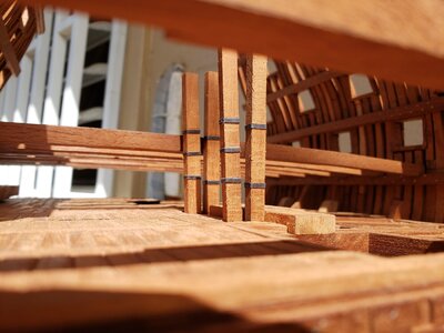
Yesterday I decide to work on all of the lower deck beams as a means of establishing total height of the storeroom and hanging magazine of the orlop deck. I first started with the beam at frame 17 and then jumping to the beam at frame (B). I chose this method so that I could use a straight edge between them thus knowing the height of all other beams between them. I was on the verge of completing all the beams when my bandsaw blade broke. I went to Home Depot (large chain hardware store) to see if they had a replacement blade to no avail. I then turned to the always reliable source, Amazon.com. I was able to find two packs of two blades each. One set was 70 1/2" by 3/8" with 6 teeth per inch (TPI) and the other set was 70 1/2" by 1/4" with 14 TPI. All in all, four blades for $41.90 was, in my opinion, an offer too good to let go.

Raymond20210227_143945.jpg20210227_143950.jpg20210227_144007.jpg20210227_144029.jpg
 
Hello everyone,
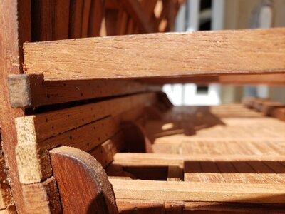
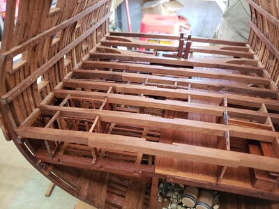
Yesterday work continued on my Victory. I mainly concentrated on the spacing material on the actual lower gun deck clamp which separates my beams. Once the beams were actually situated in place with no movement, I placed the starboard side storerooms and marked the area that needed to be cut away. I gradually worked from the aft side working forward. The first three beams we easy due to only having to worry about the storeroom. For beams four and five I also had to incorporate the hanging magazine. Little by little I was able to configure these cuts and get the beams put in place.

Today I will concentrate on the port side storeroom. This will be a little more time consuming due to having to brace certain framed areas in order to avoid having the storerooms get completely disassembled. Below are a few photos showing what I have so far.

Raymond 20210301_113649.jpg20210301_113732.jpg20210301_113750.jpg20210301_113942.jpg20210301_114202.jpg
 
Hello everyone,
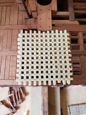
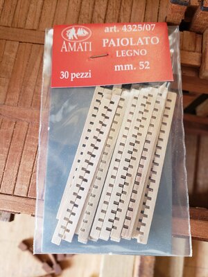
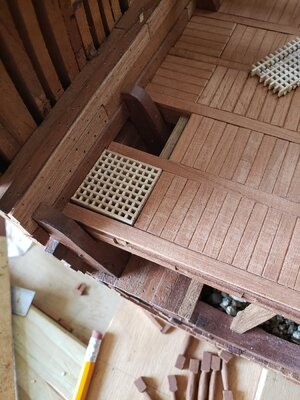
Last evening, as I was relaxing on the porch, the mailman came by and dropped off a package. When I opened it I realized that my gratings from Amati finally came in. As I was going over the quantity of the gratings (15 packs of 30 strips) I could not be more amazed at how thin and delicate this material was. As you guys may recall, I tried and made some gratings and I thought that I did pretty good. But as I was placing it on the Victory, I thought that the scale wasn't right which was the reason I purchased the gratings from Amati.

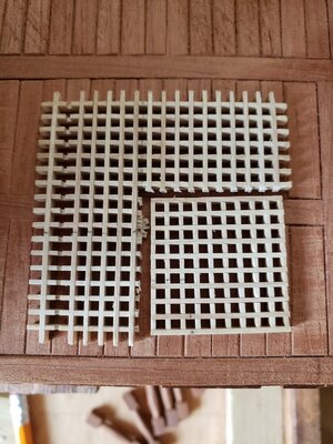
I am glad that I decided to buy the gratings. The difference between what I made and what Amati sells is quite noticeable (to put it mildly). I made an 11 strip x 11 strip square grating which is twice the size of Amati's 10 strip x 10 strip grating. Needless to say, I will be using Amati's gratings from this moment onward. Below are a few photos of what I have been doing.

Raymond 20210302_104315.jpg20210302_104325.jpg20210302_104354.jpg20210302_104404.jpg20210302_104414.jpg20210302_163042.jpg
 
Much much better in scale, but the workmanship of your was very good, just out of scale -> you need a saw with 1mm blade

according my knowledge the real gratings are laid out on a 50 mm pattern, meaning that the full battens are 50 mm x 50 mm cross-section at 50 mm intervalls - giving 50 mm x 50 mm holes
the french had slightly different pattern with spacing of 2 inches (French) to 2 inches 1/2 -> (54 and 68 mm)
Important was, that a bare feet of a seaman can easily walk over, any hole bigger than about half the width (!) of a foot would not be safe.

With a scale of 1:48 or 1:50 it would be between 1,5 and 1mm, which is looking very small but in scale correct
You have the Amati 4235/07 with 1,5mm, but also the Amati 4235/06 with 1mm would fit theoretically also in scale 1:48
Hello Uwe,
I really appreciate the feedback. I do enjoy your input due to your vast knowledge of ships. When it comes to ships and nautical knowledge you are a human encyclopedia.

Raymond
 
Hello everyone,
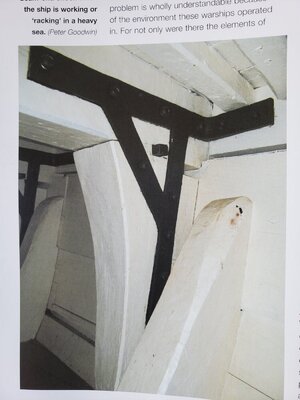
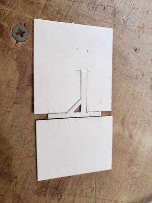
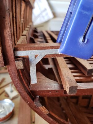
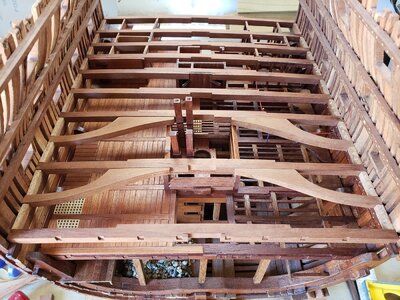
Since I have the orlop deck basically complete I drew my attention to how I would tackle the lower gundeck beams. They are already cut and shaped with the chamfer so it was just a matter of thinking about the hanging knees. Hanging knees, in general are pretty straightforward but they require metal bracing and I thought that I would either buy material to make them or use card stock.
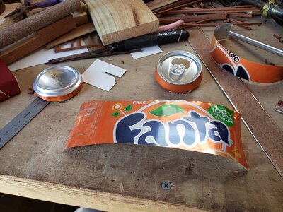
The term scratch build popped into my mind and I figured I already deviated once (or twice) and bought cannons and gratings (well worth it). So I figured I would scratch build the metal bracing thinking card stock the whole time while taking a drink of orange Fanta, (don't judge me). It then occurred to me that the aluminum can was very thin and thought it would be possible to make the metal bracing with aluminum.
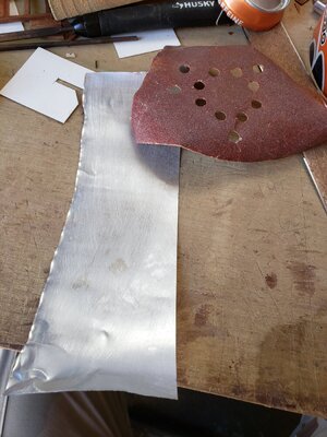
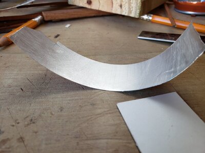
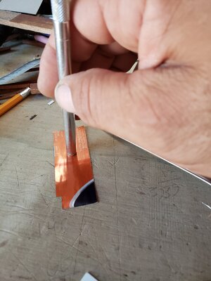
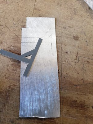
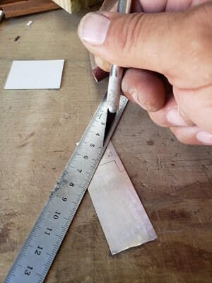
Once done with my soda, I rinsed it out in the sink and proceeded to cut the top and bottom off. Once they were removed I made a cut lengthwise and opened her up and then cut it into manageable sections. These strips had muscle memory and wanted to curl up on me. I flipped it over and used the back end of my xacto knife and gently rubbed the strips until they straightened out. Once straight, i used a pencil to see if I could transfer my pattern onto the aluminum and realized that I could not. I grabbed sandpaper and sanded the inside of the can removing the protective coating. Once done I was able to transfer my pattern. Pattern in place, I used a straight edge and my xacto and proceeded to lightly score the aluminum until it cut through (approximately 3 to 5 passes). Once cut, I reused the back end of my xacto to straighten out the edges and now I can officially say that my metal braces are scratch built.

Here are a few photos showing what I have done.

Raymond20210304_151357.jpg20210304_151405.jpg20210304_145339.jpg20210304_145405.jpg20210304_145453.jpg20210304_150536.jpg20210304_150711.jpg20210304_150725.jpg20210304_151001.jpg20210304_151025.jpg20210304_151037.jpg
 
Hello everyone,
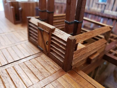
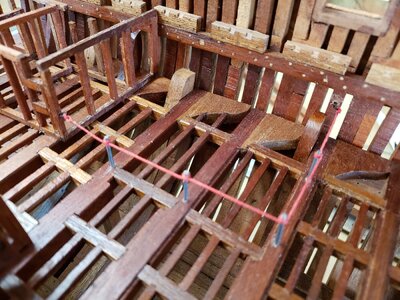
Today I installed the pump room and started working on the beam arms. Once the beam arms were made, I removed them in order to mark off or high light the midshipman's berthing area. I wanted to do this simply as a means of honoring Lord Horatio Nelson. I've seen many models of the Victory but have never seen someone emphasize this area.

I was wondering how I would go about doing this when I thought that I would rope it off with red lanyard the way they prepare walk lanes/aisles like they do in banks. The stanchions are 15mm tall and start forward of the port side storerooms upto the aft side of the pump room.

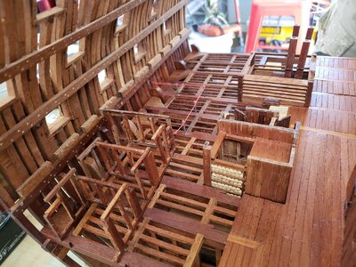
I have also started to mark and carve out the areas for the carlings. Since I started at frame (B) going aft towards frame 17, I am making sure that I carve out these beams on either side. Many cross sections omit the carving for the carlings. I am unsure if people neglect this detail or just do not think about it but my mind thinks three dimensionally and I think about the following beam that would have connected to it.

Here are the photos of what I have so far.

Raymond
20210311_134736.jpg20210311_134747.jpg20210311_134800.jpg20210311_135130.jpg20210311_135142.jpg
 
Hello Everyone,
It has been over a year since I've retired from the military and I finally find myself at liberty to follow my dream, construction of a cross section of the HMS Victory. I must confess that the liberty I am currently enjoying is a break from the my wife's "Honey-Do" list so I will try to get as much done as possible. Please do not misunderstand that I will sacrifice details in order to speed through the process but rather understand that I will give 100% attention to the construction of my project while also trying to please my wife. Everyone here should understand the, "Happy Wife, Happy Life" concept so if I disappear for a spell, know this, my wife is the Admiral and what she says goes.

I fell in love with the aspect of one day being able to scratch build a cross section of the HMS Victory. I acquired the AOTS The 100-gun ship Victory by John Mckay and HMS Victory Owners' Workshop Manual by Peter Goodwin. Both books have extensive details and I must point out that Mr. Goodwin's book has a lot more historical information and plenty of colored photos from different areas aboard the HMS Victory for reference. There is plenty of information within both books for a person to feel comfortable enough to take on this challenge. The challenging part for me was to decide how large of a cross section I wanted to build. I previously constructed a cross section of the HMS Triton but did not add enough frames to incorporate the full main channel, thus not having enough space to add all of the ratlines. With this in mind, I decided to go ahead and order plans from Mr. Mckay.

After doing research and finally getting an email address, I was able to get in contact with Mr. Mckay back in January 2019. Mr. Mckay was an absolute delight to work with and after discussing which sheets of his drawings I wanted at 1:48 scale, we exchanged information so as to send him his funds via Paypal. Once the funds cleared, Mr. Mckay sent me my drawings and I could not have been more pleased with them. If Mr. Mckay is any sign of Canadian hospitality and professionalism, then I must say that Mr. Mckay is an ambassador for our neighbors to the North. So Mr. Mckay, if you ever read this post, many thanks for your hospitality and professionalism.

Now that I have the drawings on hand, I am able to decide how large of a cross section I want to tackle. Since I want to add all of the main mast's ratlines, I have decided to start from frame (B) going aft to frame 17 in order to have the full main channel on my cross section. I also want to add the main mast all the way up to the main pole mast. Once completed, the cross section will be massive. She will be 55 1/2 inches (140.97 cm) tall from sole plate to main pole mast and 31 inches (78.74 cm) wide from either side of the main lower studding sail booms.

Since I decided to go from frames (B) to frame 17, I placed tracing paper of the drawings and finally have patterns to work with. I chose this method because I did not want to ruin the original drawings so as to keep them pristine as long as possible. After completing the drawings, I could not resist and wanted to compare one of my drawings to one of the drawings of guild's group project, the Blanford. Talk about one huge difference. The Blandford, at frame 1, is a modest 7 inches (17.78 cm) wide while the Victory, at frame (B) is a whopping 12 1/2 inches (31.75 cm) wide.

Below are a few photos of what I have thus far. Please enjoy and I look forward to updating everyone with my progress.

Raymond
Hallo Raymond alias @ziled68
we wish you all the BEST and a HAPPY BIRTHDAY
Birthday-Cake
 
Hello everyone,
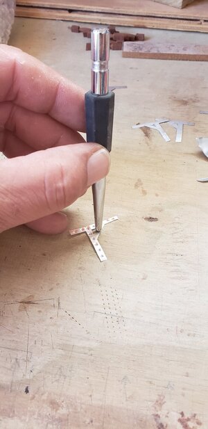
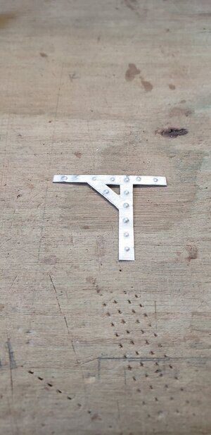
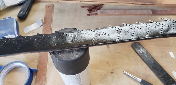
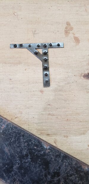
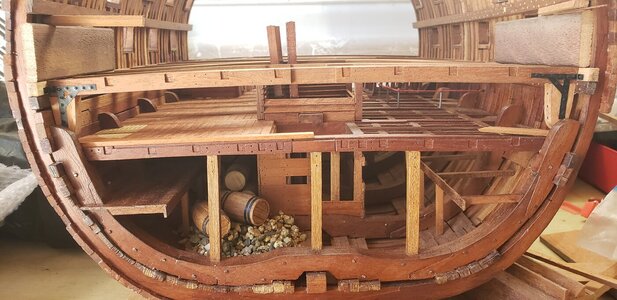
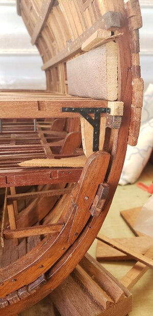
It's been almost 10 months to the day that I have had the opportunity to work on my cross section. Now that family affairs are in order and roof repairs are complete, I am hoping to get back on the saddle and continue working. Since I felt a little rusty, I decided to continue working on the metal bracing that secure the lower deck beams to its hanging knees.

The whole time I was cuting the braces, I kept thinking about how I would represent the bolts. At first I thought I would just add small drops of glue with a toothpick. My wife told me that it could be possible the paint would not stick to the glue so I had to come up with another way. What I came up with was to use an awl and lightly tap his with a small hammer and was delighted with the result. The following photos will show you what I have so far.20220103_125051.jpg20220103_125103.jpg20220103_161749.jpg20220103_125521.jpg
 
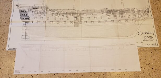
On a side note, today I received my L'Egyptienne planset. L'Egyptienne will be a rather large build and I plan to work on her frames every other week going from my Victory cross section and L'Egyptienne 1:48 full build. Here is a photo showing the size of L'Egyptienne compared to the Victory.

Raymond
20220103_173504.jpg
 
Hello everyone,
It's been almost 10 months to the day that I have had the opportunity to work on my cross section. Now that family affairs are in order and roof repairs are complete, I am hoping to get back on the saddle and continue working. Since I felt a little rusty, I decided to continue working on the metal bracing that secure the lower deck beams to its hanging knees.

The whole time I was cuting the braces, I kept thinking about how I would represent the bolts. At first I thought I would just add small drops of glue with a toothpick. My wife told me that it could be possible the paint would not stick to the glue so I had to come up with another way. What I came up with was to use an awl and lightly tap his with a small hammer and was delighted with the result. The following photos will show you what I have so far.View attachment 280429View attachment 280430View attachment 280431View attachment 280432
Well done. This makes me happy!
 
Back
Top