Bluenose - Model Shipways MS2130 - 1/64 - By JeffT [COMPLETED BUILD]

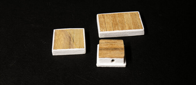
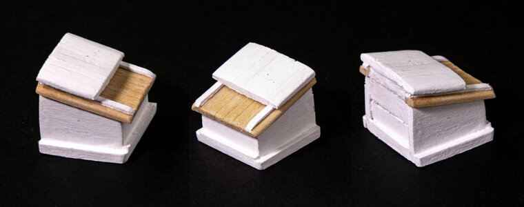
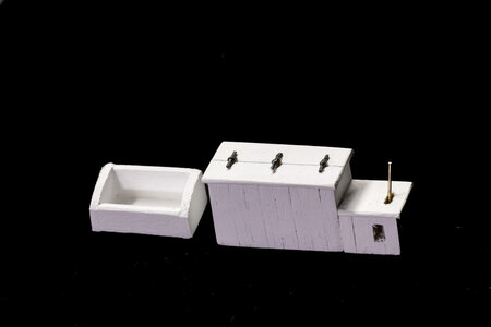
The main cabin was constructed by gluing planks to paper cutouts of the plans. This gave some rigidity as well as getting the correct size. Framing material was added around the outside and strips were glued on the inside to further strengthen and square the cabin structure. I like the planked look as opposed to making the sides and tops out of sheet material.
View attachment 372283View attachment 372281View attachment 372282
Thin walnut strips were added to the long sides to simulate bait cutting boards. The beginning construction on the entryway was started.
View attachment 372284

The roof of the cabin entryway was also glued in place.
View attachment 372285

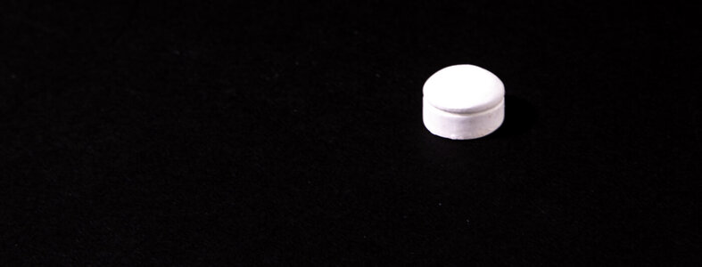
The final cabin ready for gluing to the deck. I place sandpaper on the deck (sanding side up) to sand the deck curve into the bottom of the assembly. The smoke vent was made from dowel cut at 90 degrees and glued at a right angle.
View attachment 372286
The Captain will be happy with this cabin, Jeff. Nice work!
Regards, Peter
 
The main cabin was constructed by gluing planks to paper cutouts of the plans. This gave some rigidity as well as getting the correct size. Framing material was added around the outside and strips were glued on the inside to further strengthen and square the cabin structure. I like the planked look as opposed to making the sides and tops out of sheet material.
View attachment 372283View attachment 372281View attachment 372282
Thin walnut strips were added to the long sides to simulate bait cutting boards. The beginning construction on the entryway was started.
View attachment 372284

The roof of the cabin entryway was also glued in place.
View attachment 372285

The final cabin ready for gluing to the deck. I place sandpaper on the deck (sanding side up) to sand the deck curve into the bottom of the assembly. The smoke vent was made from dowel cut at 90 degrees and glued at a right angle.
View attachment 372286
That's one neat looking aft cabin! Kudos!
 
The main cabin was constructed by gluing planks to paper cutouts of the plans. This gave some rigidity as well as getting the correct size. Framing material was added around the outside and strips were glued on the inside to further strengthen and square the cabin structure. I like the planked look as opposed to making the sides and tops out of sheet material.
View attachment 372283View attachment 372281View attachment 372282
Thin walnut strips were added to the long sides to simulate bait cutting boards. The beginning construction on the entryway was started.
View attachment 372284

The roof of the cabin entryway was also glued in place.
View attachment 372285

The final cabin ready for gluing to the deck. I place sandpaper on the deck (sanding side up) to sand the deck curve into the bottom of the assembly. The smoke vent was made from dowel cut at 45 degrees and glued at a right angle.
View attachment 372286
Good morning Jeff. You owned it! Cheers Grant
 
Looking real good Jeff. You’re giving me something seriously nice to shoot for.
 
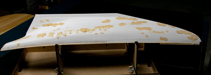
I finished the building of the hull some time ago. Here's what it looked like after applying the first coat of primer and then another round of putty.
IMG_7218.jpg

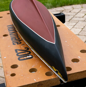
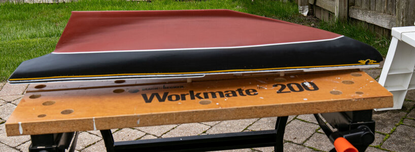
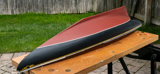
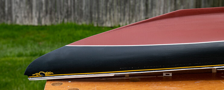
Today was a milestone day. I have puttied, sanded, primed, painted and varnished the hull. Here's a few pictures of the hull.
IMG_7250.jpgIMG_7251.jpgIMG_7254.jpgIMG_7257.jpg

I thought I was going to have to strip the entire hull after my first coat of varnish. I applied a coat of matte acrylic varnish that I have used
successfully numerous times before, but it caused cloudy coating to form over the paint. I intended to apply a couple of coats of the matte and then a couple of coats of Vallejo Premium Acrylic Polyurethane Satin Varnish. Before sitting in a corner to cry, I decided to apply a coat of the Vallejo varnish. Amazingly (and thankfully!) it dealt with the cloudy finish well and the pictures are of the hull after 5 coats of the Vallejo.
IMG_7260.jpg

The yellow scrollwork at the bow was printed on a 3D printer at about 0.5mm thickness, painted and glued in place. The "hawse lips" were added after the scrollwork was attached.
 
I finished the building of the hull some time ago. Here's what it looked like after applying the first coat of primer and then another round of putty.
View attachment 373212

Today was a milestone day. I have puttied, sanded, primed, painted and varnished the hull. Here's a few pictures of the hull.
View attachment 373215View attachment 373216View attachment 373217View attachment 373218

I thought I was going to have to strip the entire hull after my first coat of varnish. I applied a coat of matte acrylic varnish that I have used
successfully numerous times before, but it caused cloudy coating to form over the paint. I intended to apply a couple of coats of the matte and then a couple of coats of Vallejo Premium Acrylic Polyurethane Satin Varnish. Before sitting in a corner to cry, I decided to apply a coat of the Vallejo varnish. Amazingly (and thankfully!) it dealt with the cloudy finish well and the pictures are of the hull after 5 coats of the Vallejo.
View attachment 373219

The yellow scrollwork at the bow was printed on a 3D printer at about 0.5mm thickness, painted and glued in place. The "hawse lips" were added after the scrollwork was attached.
I like the matted black and red finish, Jeff. Sometimes you are halve way on a painting job and it shows bad.
And then surprisingly enough, it stands out very well after a new layer. A nice job done.
Regards, Peter
 
I finished the building of the hull some time ago. Here's what it looked like after applying the first coat of primer and then another round of putty.
View attachment 373212

Today was a milestone day. I have puttied, sanded, primed, painted and varnished the hull. Here's a few pictures of the hull.
View attachment 373215View attachment 373216View attachment 373217View attachment 373218

I thought I was going to have to strip the entire hull after my first coat of varnish. I applied a coat of matte acrylic varnish that I have used
successfully numerous times before, but it caused cloudy coating to form over the paint. I intended to apply a couple of coats of the matte and then a couple of coats of Vallejo Premium Acrylic Polyurethane Satin Varnish. Before sitting in a corner to cry, I decided to apply a coat of the Vallejo varnish. Amazingly (and thankfully!) it dealt with the cloudy finish well and the pictures are of the hull after 5 coats of the Vallejo.
View attachment 373219

The yellow scrollwork at the bow was printed on a 3D printer at about 0.5mm thickness, painted and glued in place. The "hawse lips" were added after the scrollwork was attached.
Good morning Jeff. Great job. Cheers Grant
 
I finished the building of the hull some time ago. Here's what it looked like after applying the first coat of primer and then another round of putty.
View attachment 373212

Today was a milestone day. I have puttied, sanded, primed, painted and varnished the hull. Here's a few pictures of the hull.
View attachment 373215View attachment 373216View attachment 373217View attachment 373218

I thought I was going to have to strip the entire hull after my first coat of varnish. I applied a coat of matte acrylic varnish that I have used
successfully numerous times before, but it caused cloudy coating to form over the paint. I intended to apply a couple of coats of the matte and then a couple of coats of Vallejo Premium Acrylic Polyurethane Satin Varnish. Before sitting in a corner to cry, I decided to apply a coat of the Vallejo varnish. Amazingly (and thankfully!) it dealt with the cloudy finish well and the pictures are of the hull after 5 coats of the Vallejo.
View attachment 373219

The yellow scrollwork at the bow was printed on a 3D printer at about 0.5mm thickness, painted and glued in place. The "hawse lips" were added after the scrollwork was attached.
Looking great
 

Attachments

  • Bluenose Scroll Work - Port & Starboard (1).stl
    290.5 KB · Views: 19
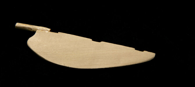
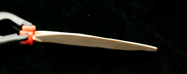
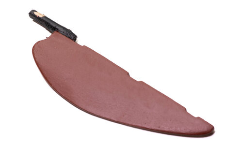
I finished the rudder. This is a laser cut pierce that requires some shaping as per the plans. It is thinner on the trailing edge that it is on the edge next to the stern post. A post is glued to the rudder that goes into the slot at the stern of the hull. I ended up pinning it with a small nail to give it a bit more rigidity. The rudder was painted to match the lower part of the hull.

IMG_7214.jpgIMG_7217.jpgIMG_7272.jpg
 
I finished the rudder. This is a laser cut pierce that requires some shaping as per the plans. It is thinner on the trailing edge that it is on the edge next to the stern post. A post is glued to the rudder that goes into the slot at the stern of the hull. I ended up pinning it with a small nail to give it a bit more rigidity. The rudder was painted to match the lower part of the hull.

View attachment 374534View attachment 374535View attachment 374536
Good morning Jeff. Looking great. The rudder kin the BN always finishes off the shape of that beautiful hull. Looking forward to it being installed. Cheers Grant
 
More deck structures assembled.

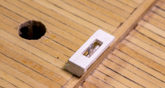
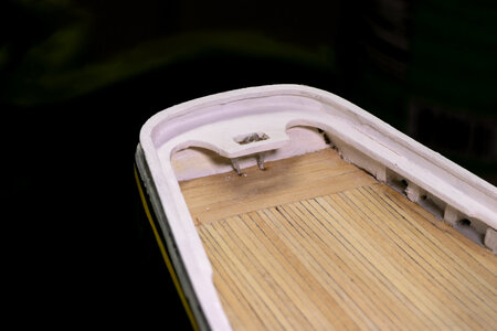
Sheet boom buffers. The one in the stern was problematic. The legs were too short, so I had to cut them off, drill holes and add some 0.5mm nails for the legs. Along with being too short, I should have installed the piece before doing the stern rail. I could not find a way to install the piece under the rail so it would extend into the slot in the rail correctly. I ended up cutting the slot for the sheet buffer boom off of the rail and then installing the piece. Once in place I glued, puttied, sanded and repainted the slot area of the rail.
IMG_7246.jpgIMG_7249.jpg

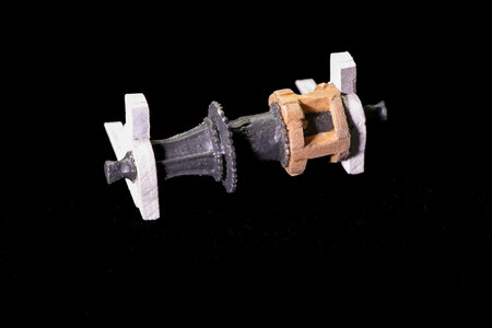
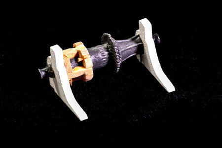
Next was working on the bow machinery. Once you have spent some time studying the plans drawings it makes some sense regarding where everything goes. I started with the windlass. This part requires the port end built for hauling chain and the starboard end built for hauling rope. Brass wire was glued to the port end of the windlass and a wooden "cage" was built around the starboard end. The windlass was painted and then the laser cut supports were assembled with the windlass. I painted the moving parts of the machinery a grimy black/grey color and the non-moving parts black. Wooden supports are white.
IMG_7265.jpgIMG_7266.jpgIMG_7269.jpg

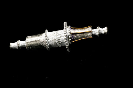
The next piece I worked on was the drive from the engine. There is a large gear that needs to fit onto the supplied Britannia metal shaft unit. The difficult part is that the unit has to have the shaft removed and replaced with a new axle to fit the separate larger gear. So, I cut the Britannia shaft off and drilled the faired ends and the small sprocket. I use a long brass nail for the new axle.
IMG_7263.jpg

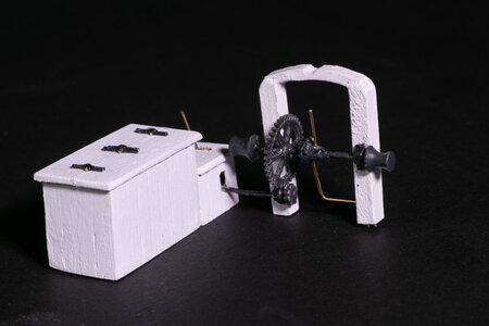
Onto the engine box and the box for extra chain. The engine box was made from 2 solid pieces of scrap covered with thin planking. The cover was made and then scored more deeply to represent a 2-part hinged cover. Hinges were mad from small brass rod and copper strips (scrounged from extra materials from my whaleboat build). Slots were cut into the lower part of the engine box for the sprocket shaft and the handle for engaging the gears inside the box. For those builders who are interested the plans show the equipment that would need to be made if you wanted to have the hinged top open.
IMG_7271.jpg

Finally, the last piece was constructed and the gears put into place. I simulated the lever that engages the chain sprocket with a L-shaped piece of brass wire. Here's what the engine box and gearing will look like on the deck.
IMG_7275.jpg
 
More deck structures assembled.

Sheet boom buffers. The one in the stern was problematic. The legs were too short, so I had to cut them off, drill holes and add some 0.5mm nails for the legs. Along with being too short, I should have installed the piece before doing the stern rail. I could not find a way to install the piece under the rail so it would extend into the slot in the rail correctly. I ended up cutting the slot for the sheet buffer boom off of the rail and then installing the piece. Once in place I glued, puttied, sanded and repainted the slot area of the rail.
View attachment 376776View attachment 376777

Next was working on the bow machinery. Once you have spent some time studying the plans drawings it makes some sense regarding where everything goes. I started with the windlass. This part requires the port end built for hauling chain and the starboard end built for hauling rope. Brass wire was glued to the port end of the windlass and a wooden "cage" was built around the starboard end. The windlass was painted and then the laser cut supports were assembled with the windlass. I painted the moving parts of the machinery a grimy black/grey color and the non-moving parts black. Wooden supports are white.
View attachment 376781View attachment 376782View attachment 376783

The next piece I worked on was the drive from the engine. There is a large gear that needs to fit onto the supplied Britannia metal shaft unit. The difficult part is that the unit has to have the shaft removed and replaced with a new axle to fit the separate larger gear. So, I cut the Britannia shaft off and drilled the faired ends and the small sprocket. I use a long brass nail for the new axle.
View attachment 376780

Onto the engine box and the box for extra chain. The engine box was made from 2 solid pieces of scrap covered with thin planking. The cover was made and then scored more deeply to represent a 2-part hinged cover. Hinges were mad from small brass rod and copper strips (scrounged from extra materials from my whaleboat build). Slots were cut into the lower part of the engine box for the sprocket shaft and the handle for engaging the gears inside the box. For those builders who are interested the plans show the equipment that would need to be made if you wanted to have the hinged top open.
View attachment 376784

Finally, the last piece was constructed and the gears put into place. I simulated the lever that engages the chain sprocket with a L-shaped piece of brass wire. Here's what the engine box and gearing will look like on the deck.
View attachment 376785
Good morning Jeff. Good plan to make the stern boom bigger fit- you pulled it off. Your engine box and windlass are great. Well done on the hinges as I see many guys struggle with these. Cheers Grant
 
More deck structures assembled.

Sheet boom buffers. The one in the stern was problematic. The legs were too short, so I had to cut them off, drill holes and add some 0.5mm nails for the legs. Along with being too short, I should have installed the piece before doing the stern rail. I could not find a way to install the piece under the rail so it would extend into the slot in the rail correctly. I ended up cutting the slot for the sheet buffer boom off of the rail and then installing the piece. Once in place I glued, puttied, sanded and repainted the slot area of the rail.
View attachment 376776View attachment 376777

Next was working on the bow machinery. Once you have spent some time studying the plans drawings it makes some sense regarding where everything goes. I started with the windlass. This part requires the port end built for hauling chain and the starboard end built for hauling rope. Brass wire was glued to the port end of the windlass and a wooden "cage" was built around the starboard end. The windlass was painted and then the laser cut supports were assembled with the windlass. I painted the moving parts of the machinery a grimy black/grey color and the non-moving parts black. Wooden supports are white.
View attachment 376781View attachment 376782View attachment 376783

The next piece I worked on was the drive from the engine. There is a large gear that needs to fit onto the supplied Britannia metal shaft unit. The difficult part is that the unit has to have the shaft removed and replaced with a new axle to fit the separate larger gear. So, I cut the Britannia shaft off and drilled the faired ends and the small sprocket. I use a long brass nail for the new axle.
View attachment 376780

Onto the engine box and the box for extra chain. The engine box was made from 2 solid pieces of scrap covered with thin planking. The cover was made and then scored more deeply to represent a 2-part hinged cover. Hinges were mad from small brass rod and copper strips (scrounged from extra materials from my whaleboat build). Slots were cut into the lower part of the engine box for the sprocket shaft and the handle for engaging the gears inside the box. For those builders who are interested the plans show the equipment that would need to be made if you wanted to have the hinged top open.
View attachment 376784

Finally, the last piece was constructed and the gears put into place. I simulated the lever that engages the chain sprocket with a L-shaped piece of brass wire. Here's what the engine box and gearing will look like on the deck.
View attachment 376785
You made some nice small parts, Jeff. The engine box and driving gear for the windlass have nice small details.
Regards, Peter
 
Some more details.
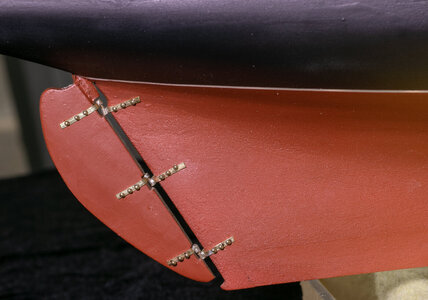
What are the 2 most difficult tasks (for me at least) when building a ship? Ladders (thankfully the Bluenose doesn't have any) and attaching the rudder. Pintles and gudgeons were made using 1/16" brass strips with brass tubing and a brass rod to hold the parts together. I put this step off about as long as I could. After a few false starts with soldering tubing to the brass strips I finally ended up with 3 that were acceptable. The rudder evens moves as it should.
IMG_7302.jpg

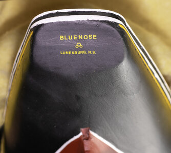
I found some yellow rub on letters of various sizes online and used them to add the ship's name and home port on the stern. I painted Vallejo Satin Varnish over them to add some protection to the letters.
IMG_7277.jpg
 
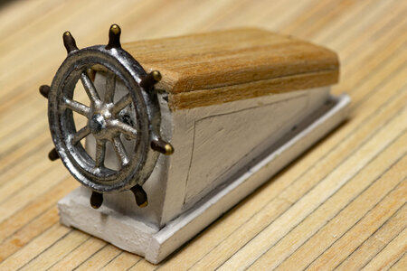
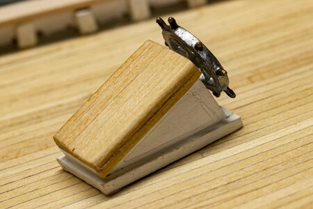
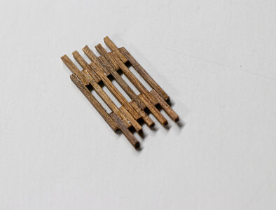
I have nearly completed the deck structures. There is a platform next to the ship's wheel that needed to be fabricated. I used some 1/64 square stock from a previous build for this. I glued strips and spacers together and then cut it to size. After sanding it was mounted to the deck next to the wheel. I was suprised now much difficulty this little piece gave me. I think I made 3 versions to get the final piece.
IMG_7279.jpg

Here it is on the ship with other stern deck structures.
IMG_7285.jpg

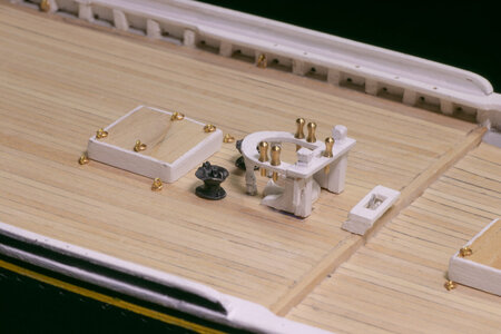
The fife rail was constructed according to plans and using laser-cut, stock square wood, and metal pedestals. I still need to add the piece under the rail for the foresail boom crutch to set in. After looking at the picture I set the rail knees onto to the deck as opposed to the raised position shown in the picture.
IMG_7305.jpg

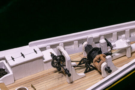
Here's the completed machinery on the fore deck. It was a lot of work, but I am pleased with the overall appearance. Just noticed that I lost my lever in the gearbox. I'll have to replace that. Also I need a bit of deck cleanup under the gears.
IMG_7300.jpg

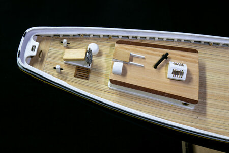
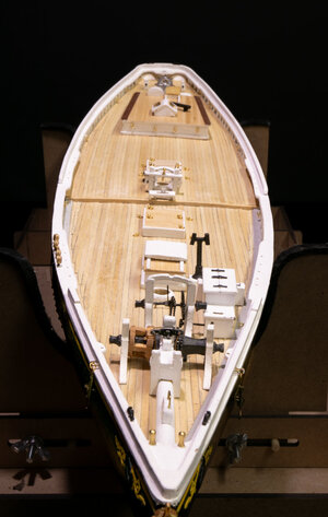
And finally, the bow to stern view of the deck as it is today. I have not assembled the catheads or anchors yet. The catheads appear to be quite fragile and I am certain I would bend/break them while rigging. I hope to add them after most of the rigging has been completed.
IMG_7307.jpg
 
I have nearly completed the deck structures. There is a platform next to the ship's wheel that needed to be fabricated. I used some 1/64 square stock from a previous build for this. I glued strips and spacers together and then cut it to size. After sanding it was mounted to the deck next to the wheel. I was suprised now much difficulty this little piece gave me. I think I made 3 versions to get the final piece.
View attachment 377260

Here it is on the ship with other stern deck structures.
View attachment 377261

The fife rail was constructed according to plans and using laser-cut, stock square wood, and metal pedestals. I still need to add the piece under the rail for the foresail boom crutch to set in. After looking at the picture I set the rail knees onto to the deck as opposed to the raised position shown in the picture.
View attachment 377263

Here's the completed machinery on the fore deck. It was a lot of work, but I am pleased with the overall appearance. Just noticed that I lost my lever in the gearbox. I'll have to replace that. Also I need a bit of deck cleanup under the gears.
View attachment 377262

And finally, the bow to stern view of the deck as it is today. I have not assembled the catheads or anchors yet. The catheads appear to be quite fragile and I am certain I would bend/break them while rigging. I hope to add them after most of the rigging has been completed.
View attachment 377264
Good evening Jeff. All the little details are adding to your BN. It is a busy Schooner as of stating to look so. Well done. Cheers Grant
 
Back
Top