• Win a Free Custom Engraved Brass Coin!!!
    As a way to introduce our brass coins to the community, we will raffle off a free coin during the month of August. Follow link ABOVE for instructions for entering.

School for Shipmodel Building School for model ship building

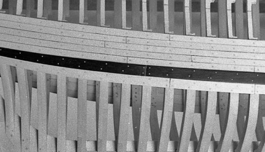
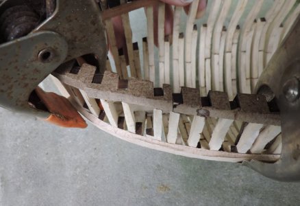
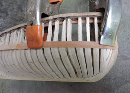
Adding the wales depend on the wood you select and the type of hull a solid hull, plank on bulkhead or plank on frame. It is clear a framed hull makes holding the wales in place much easier than trying to hold them against a solid hull. Because wales are thicker than the planking it helpful to soak the end in hot water. Here you see the difference in color before the orange clamp and after the clamp. The end section was soaking in hot water for about 15 minutes.
wale8.jpg

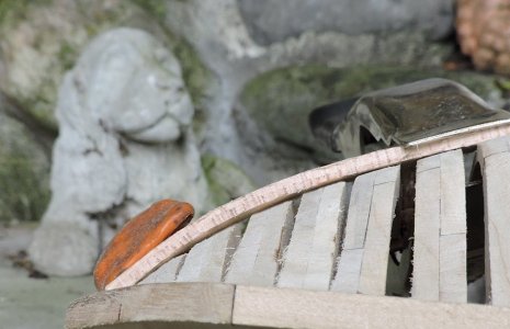
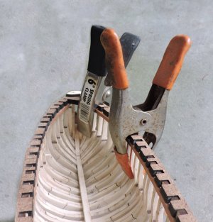
The advantage to a frames hull or a hull built as a solid shell, you can clamp the wales to the hull.

wale9.jpgwale10.jpg

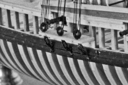
so for the wood, because wales are usually black builders will try and use Ebony. Which was used by mater builders. The problem with Ebony is it does not like to bend, it is somewhat brittle. What Hahn did was to laminate thin ebony to a bendable wood. A wale at the bow not only bends along the hull but it also has a twist so Hahn created a positive and negative "mold of the bow and clamped the wale between the two.
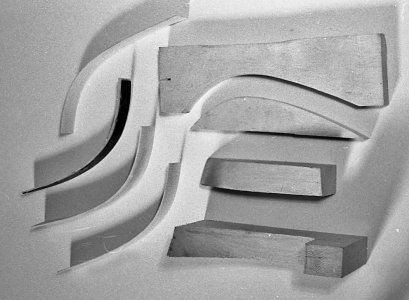
xconfed62.jpg

You can see on some of his models the laminate wale.
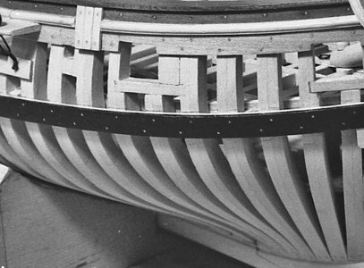
wale7.jpg

Other solutions is to use a bendable wood and stain it black or use a darker wood besides Ebony. Some woods just do not like to bend while others bend well. What you see being used here is Red Maple also called Soft Maple which is really not that soft, but it takes bending quite well. In general, the softer the wood the better it will bend but soft wood when soaked in water will dent from clamping. hard wood will not dent as easy but harder to bend. The answer is not too hard and not to soft. There are woods in the rosewood family that are dark and will bend, the problem is gluing, they have an oil in them that glue will not hold. Thickness also plays a roll in bending wales. The thicker the material the better chances of it bending. That sounds counter intuitive but the thinner the wood is it gets to a point its structure becomes weak and it will break before it bends.
 
Last edited:
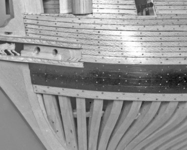
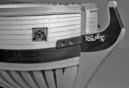
Wales can be one timber or made up of a number of strakes.

OH! another ship term lets define it before moving on

On a vessel's hull, a strake is a longitudinal course of planking or plating which runs from the boat's stempost (at the bows) to the sternpost or transom (at the rear)
.

lets take a look

here is a wale made up of one large plank

wale1.jpg

here are wales made up of a number of strakes


wale2.jpgwale3.jpgwale4.jpg

here is the Niagara and the wales have 5 strakes

wale5.jpg
 
Last edited:
The big problem builders run into is the fact a wale not only bends along the hull but it has a twist to it. Let me show you what i mean.
Looking at the top edge of the wale it bends nicely along the hull sitting tight to the frames.

wale11.jpg

But when you look at the bottom edge it is a different story the wale does not sit on the frame.


wale12.jpg

if your planking the hull this may not matter because the plank butting the lower edge of the wale might cover the void. but if you not planking the lower hull that void will show. How do you fix this? you can try to twist and clamp the wale but you run the chance of denting the wale from the pressure of the clamp plus the fact the wood your using may not take the bend and twist.
The solution is the "strakes" here you see a wale make up of one timber and what your trying to do it bend something that is straight to conform to a curves surface. If the wood is pliable enough you might succeed but that is a big maybe. The other example is breaking the wale into strakes now the narrower pieces will conform to the curved surface of the frame. to make this work the edges of the strakes have a bevel so they fit tight to one another.

Planning the wales there is a limit in the number of strakes you can use in model building. Planking in model building is thicker than what was actually used. A two inch thick plank at 1:48 scale is .040 quite thin and depending on the wood at its limit of strength for bending. Using slightly thicker helps from sanding through the planking and thicker is stronger. Breaking down a wale into strakes you do not want the thickness to exceed the width because then you will be trying to bend a timber edge wise which is harder to do. The limit is square.


wide planks.jpg
 
ok class dismissed

chance are there will not be a class next Saturday because the wife and i are going on vacation to celebrate 45 or 46 or 47 years together i lost count a long time ago. We are leaving tomorrow with an open end of returning. No model work this coming week.
 
I may have missed something, but what is your method for fairing the interior of the POF frames for truly smooth transitions?

you did not miss anything, i did not cover fairing the interior of the hull. The sir Edward Hawke project is somewhat of simplified build with the idea of "if you do not see it don't bother with it." This project is more for a first time semi scratch builder wanted to build a framed-up hull.
However you do bring up a valid and worthy subject to discuss so i will cover it in another build.
 
Richard
Hold on for expert advice from Dave.
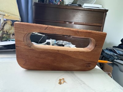
In the meantime here’s what I use for interior fairing. It’s called a sanding sled. The bottom corners are rounded so as to not catch on frames that are standing proud of the others.
Works great.

View attachment 543039
Interesting. I guess it would be sized to the project scale and particularly good for taking the bulk of the material off. Ii was thinking of high grit sandpaper stuck to a thin flexible plank for the very fine top layer?
 
Hull Lines & Planking Thickness: while I agree with Dave that while hull lines are USUALLY drawn to the inside of the planking such is not always the case. Here, I am talking about original drafts as one would order from Royal Museums Greenwich, not one specifically drawn for POF modeling like Harold Hahn’s.

Lines drawings drawn for building ships; wooden or steel are drawn to Moulded Dimensions (inside of planking or plating). This is necessary to provide the mould loft with information to lay out accurate frame shapes. Otherwise, the lofts men would have to deduct this thickness during the lofting process. This would also be true when half models were used instead of drawings.

On the other hand, when the Royal Navy captured foreign vessels they would sometimes record the hull lines. Chapelle writes that they had specially equipped drydocks for this purpose. This process would produce a Table of Offsets that would then be used to make a drawing. This drawing would be used to evaluate the captured vessel’s design not to build a new one. Since, this recording process involved measuring an existing vessel, these lines would be drawn to the OUTSIDE of the planking.

In other words, it depends on the situation.

My last project was a 1:32 scale RN longboat. My series of warships’ boats feature carved outside and inside hulls so it was necessary to adjust the lines on the Admiralty draught to ADD the planking thickness.

Roger
I did a lot of small boat and yacht designing as part of my boatbuilding career and design offsets were always to the outside of the hull. This was to obtain the correct volume of the vessel for displacement calculations etc. The vessel was then lofted onto a floor and the corrected lines and body plan had the planking thickness taken off for the construction frames to be built. I built a number of boats from a range of designers - Laurent Giles, Sparkman and Stephens, Gary Mull, John Specer, Alan Wright,to name a few and all the table of offsets were to the outside of the hull.
 
I am a graduate of the Naval Architect and Marine Engineering program at the University of Michigan. (Class of 1965). Back then it was a “big ship” program. The professors all had experience working in major shipyards building large steel hulled vessels. Small craft design was dismissed as an art rather than a science, not to be taught in a University Setting. In 1965, computers were large machines with very limited access to students and many faculty members so the computerized programs for analyzing small craft performance did not yetexist.

A beginning course, included making a lines drawing from a table of offsets (traced in ink- what a mess!). The vessel was the MV Ranger, a passenger vessel used to ferry visitors to and from Isle Royal on Lake Superior. Lines were drawn to the inside of the steel hull plating, as were lines drawn for other projects later on. In a large steel hulled vessel the shell plating is much smaller in proportion than that for a wooden hulled small craft. In 1965, it could be ignored in hull form calculations for large vessels and the loftsmen could use offsets from the design office without correcting for shell plating thickness.

That was American practice for large vessels way back in 1965.
Roger
 
Back
Top