• Ships of Scale has incorportated an extra level of security when you log In. Please follow on-screen prompts to acknowledge that you are not a robot via a "Check Box" or a "Pictorial Check Box Puzzle". This is needed due to higher level of AI Activity Security.
  • SUBSCRIBE TO SHIPS IN SCALE TODAY!

    The beloved Ships in Scale Magazine is back and charting a new course for 2026!
    Discover new skills, new techniques, and new inspirations in every issue.

    NOTE THAT OUR NEXT ISSUE WILL BE July/August 2026
  • Win a Free Custom Engraved Brass Coin!!!
    As a way to introduce our brass coins to the community, we will raffle off a free coin during the month of August. Follow link ABOVE for instructions for entering.

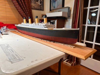
Titanic Trumpeter 1/200 by InkMot

Building the Display Base​


For my display base, I was inspired by Peter Davies-Garner’s book, “RMS Titanic: A Model Maker’s Manual”. In it, he states:


I chose an oak plank which I cut to 5’ (153cm) in length and added molding on all sides. I finished it with tung oil.

​

View attachment 617021View attachment 617018​

I used a track saw to cut the oak board to length. A regular circular saw would’ve been fine, but I wanted to make sure that my corners were perfectly square so that my trim miters would look clean.

View attachment 617020View attachment 617017View attachment 617023​

Lot’s of sanding: 60g/120g/220g/320g to make it smoooth. I like Osmo Polyx-Oil for projects like this. It wipes on with a cloth and preserves the feel of the oak.

View attachment 617022View attachment 617014
I taped several blank sheets of paper together to trace the shape of the hull, which I reduced to groups of strip lengths. Using the template, I marked out the locations for each strip length on the oak board. The strips (“blocks”) were made from 1/4” (7cm) poplar and cut to length using a small miter saw. Each was glued to the base using Gorilla wood glue and spaced using a scrap strip as a spacer.

View attachment 617008
Eventually, after much cutting and gluing, you get something like this.

​

Mounting the Hull on the Base​

The hull was attached to the base using three (3) No 8, brass wood screws. One screw is amidships with the other two spaced 10” forward and 10” aft, along the centerline.
View attachment 617010

I inserted a short strip in the space between the mounted strips to provide mounting points for the hull and to drill the pilot hole through from the top. This helped later to locate the hole when I drilled another pilot hull from beneath up into the hull and countersunk the hole.

View attachment 617009
The model was carefully centered fore and aft and left to right on the base. I then held it in place using painter’s tape and a 25lb dumbbell. This arrangement kept things steady while I drilled pilot holes up into the hull from the bottom and then drove the screws.
View attachment 617024
One of the brass, counter-sunk screws holding the model to the base.

View attachment 617011View attachment 617013

I’m satisfied with the result. Now that the model is mounted, I can proceed with installing the propellers and the boat deck structures. Of course, moving now involves carrying the entire base and ship assembly, but at least the model has more protection.
Great Work!

With the 3D printed funnels, are you going to drill in holes from the stays?

The drydock method looks great on your Titanic. Its the same plan I will use on my 1:350 Titanic when I get to that point. I haven't thought about the layout yet, but your method looks great and I will probably use it when I get there. Thank you for the inspiration on you build

Pete
 
Great Work!

With the 3D printed funnels, are you going to drill in holes from the stays?

The drydock method looks great on your Titanic. Its the same plan I will use on my 1:350 Titanic when I get to that point. I haven't thought about the layout yet, but your method looks great and I will probably use it when I get there. Thank you for the inspiration on you build

Pete
Thanks!

I’m still researching the material I’ll eventually use for the stays. I’ll likely secure whatever I choose using a dot of CA. The material of the 3D funnels is brittle and would not likely allow for a clean hole. Also, at 1/200 scale, any hole I’d drill would equate to a foot or more in diameter in scale.

I found that laying out the strips for the cribbing to be more trial and error. You’ll need to place your hull on them while they’re loose to see what looks best to you. For example, you can do a gradual tapering of length along the hull or you can opt to change sizes in groups like I did. I spent months pondering my decision. ;)
 
Thanks!

I’m still researching the material I’ll eventually use for the stays. I’ll likely secure whatever I choose using a dot of CA. The material of the 3D funnels is brittle and would not likely allow for a clean hole. Also, at 1/200 scale, any hole I’d drill would equate to a foot or more in diameter in scale.

I found that laying out the strips for the cribbing to be more trial and error. You’ll need to place your hull on them while they’re loose to see what looks best to you. For example, you can do a gradual tapering of length along the hull or you can opt to change sizes in groups like I did. I spent months pondering my decision. ;)
Thanks for the info.
Yup I was wondering about the brittleness of the funnels. I considered seeing if clipped fishhooks (the eyelets would be reserved and used) for stays. That way I could use a very small drill bit to make a pin hole for the eyelet to attach to the funnel and use that as my stay anchor point. But then you run into the brittleness issue again.

looking forward to your solution

Pete
 
I'll probably use the PE shakes that came with my KA detail kit.

You can see a video of Ben at the Midwest Model Shop installing his here:

image.jpg
 

Navigation Bridge (Part 2)​

Whereby I (some may say) unnecessarily add more detail to the roof of the bridge and assemble the side walls, etc.

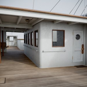
The Titanic's Navigation Bridge had beams supporting its roof that ran transversely. There were also larger supports running fore and aft with two support columns. Since the bridge is open on either side - even with the side walls installed, I felt this would make a nice touch.
IMG_3064.JPG
Here's a nice rendering from Titanic Honor and Glory

IMG_3067.jpeg
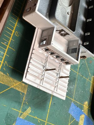
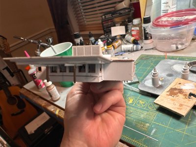
I bult my beams with styrene strips. The support columns are brass rods. I added glazing and frames to all of the windows and inserted the PE interior wall details from the MK1 detail kit.


IMG_3071.jpeg

IMG_3081.jpegIMG_3080.jpeg
Navigation Bridge in place with side walls installed. The ceiling beams can be seen...if you look. ;-)
 

Compass Platform​

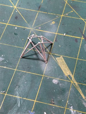
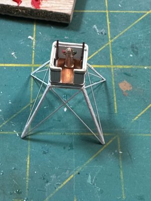
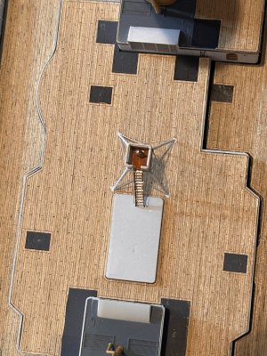
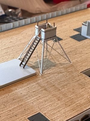
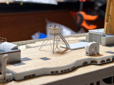
I used the platform from the MK1 PE detail kit combined with the support legs from the Trumpeter kit to create my compass platform. The 3D-printed MK1 platform was much more accurate while the Trumpeter stock support legs were thinner and closer to scale than the MK1 3D-printed legs. The access ladder came from the MK1 PE.

IMG_3221.jpegIMG_4081.jpeg
The Trumpeter support legs are on the left, the MK1 legs are on the right. While the MK1 legs had more detail, they are twice as thick as they should be. I figured that the scale of the legs was more important that the inclusion of a few ridges, etc.

IMG_3223.jpeg
Together, they make a nice pair.

IMG_3229.jpegIMG_3227.jpegIMG_3954.jpeg
Here is the compass platform in place on the Boat Deck. Note the staircase and compass binnacle are installed.
 

Funnel Details​

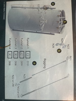
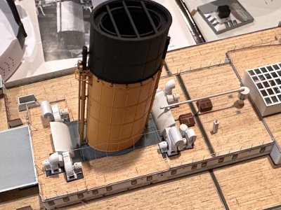
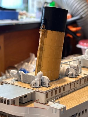
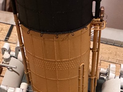
There are several areas of detail work that are required for the funnels. I elected to go with the Model Monkey (MM) 3D-printed funnels (see more information about this here: https://shipsofscale.com/sosforums/threads/titanic-trumpeter-1-200-by-inkmot.13004/post-494192). The MM funnels already include a lot of detail, specifically the pulleys mounted on the top rim that support the climbing rigging needed for funnel maintenance. While the MK1 kit provided these pulleys in PE, they seemed out of scale to me and redundant to the MM pulleys. Plus, and this is more important, I am lazy. So, no PE pulleys. This leaves the build out of the forward maintenance platform, access ladder and the pad eyes for the funnel stays.

IMG_3792.jpeg
This photo shows the MK1 PE maintenance platform in place (sorry, no build photos) and the steam whistles mounted. The steam whistles are included with the MM funnels.

IMG_3851.jpegIMG_4082.jpeg
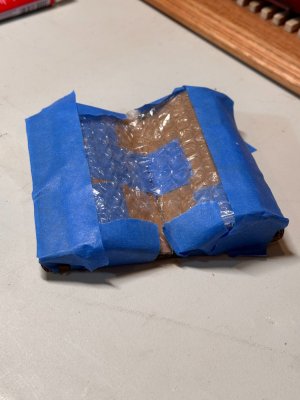
I used the access ladders from the MK1 PE and folded the sides in, rather than leave them flat. I think this is more to scale. I built a cradle for each funnel to rest in while I added details (right photo). This prevented damage and made mounting the tiny PE parts easier.

IMG_3795.jpeg
The funnel stay pad eyes have been glued in place and painted with black enamel for more support. The funnel stay PE parts will connect here and run to the Boat Deck. @PeteG

After all of the details were installed on each funnel, the funnels were secured to the deck using E6000 cement and a couple of drops of CA. This was so that I could adjust the funnels after placing them to ensure that they were aligned. I'm still not completely satisfied and I'll likely move Funnel 1 a tiny bit before installing the stays.
 
Last edited:

Boat Deck Details​

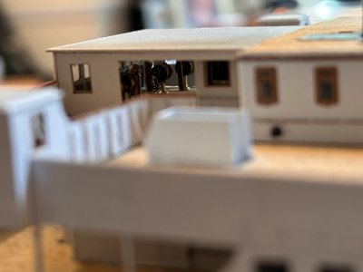
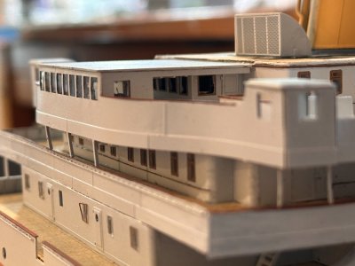
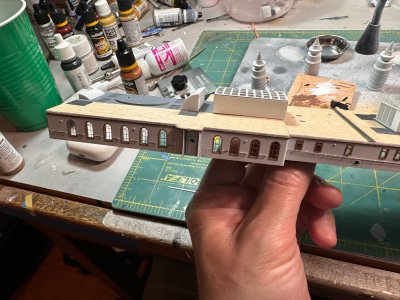
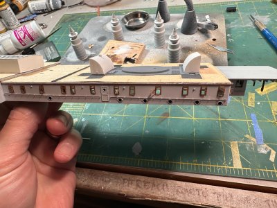
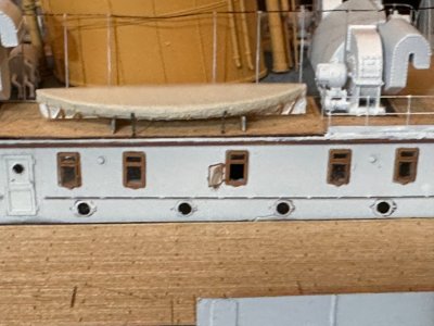
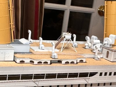
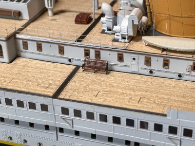
I've been slowly working my way aft, installing railings, awning supports, ventilators, benches, and collapsible boats A and B, etc. It's been slow-going. A key milestone to starting this detail work was mounting the funnels. You don't want to be threading the funnels around deck details.


IMG_3069.jpegIMG_3068.jpeg
Each deck house had to get hand rails installed and painted. Here's an examples of the hand rail work. Each one of these structures was glued to the deck with good 'ol Tester's model cement and a bunch of heavy weight (I use steel 3-2-1 blocks).

IMG_4019.jpeg
The awning supports over the officer's quarters were pretty finicky to install. The vertical stanchions are painted white and the connecting cable is black. I still need to adjust the forward stanchion on the port side. (sigh)

IMG_4051.jpegIMG_4055.jpeg
After installing the railings and ventilators, etc. on the Officer's quarters roof, I was able to paint up the collapsible boats (MK1 detail) and mount them on their PE stands with PE tie-downs. This was more work than you'd think.

IMG_4015.jpeg
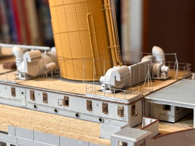
Moving aft, I've begun installing more ventilators (note that they all have grills made of PE installed, several ventilators are in two parts. All of the ventilators are mounted on PE plates, painted a dark grey. Railings are installed alongside of this work.


IMG_4083.jpegIMG_4053.jpeg
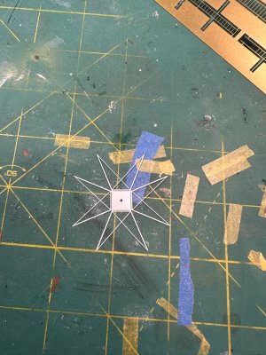
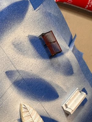
Note the first set of MK1 benches in place. My first two were a learning experience. You form them from flat PE, using the template on the lower right of the photo. You then add a center support and the two end pieces with hand rests. The trick is to get them all aligned so that the bench sits level and square, which is quite a struggle. ;-)


All of this detail work in the center of the Boat Deck needs to be completed so that I can add the funnel stays and then move to the lifeboats.

IMG_4085.jpeg

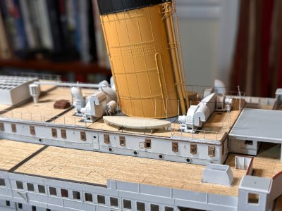
Anyway, here's where I'm at as of 27 September, 2026
 
Back
Top