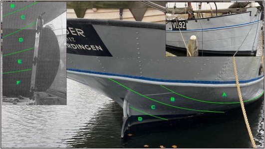
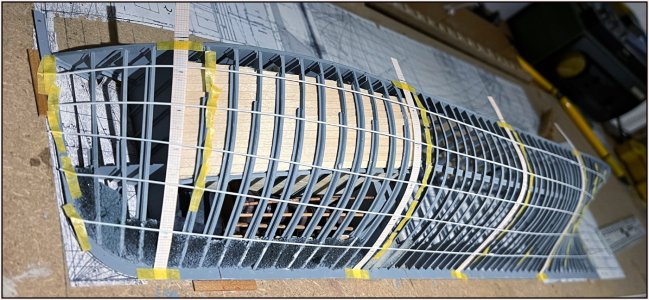
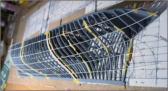
I want to combine the application of the cement in the triangle between the keel beam and the keelson with the application of at least the 1st row of hull plates. The row that is connected to the keel beam.
But to make that I need to have the plan ready for all hull plates.
From the keel to the corner profile on the side of the deck there are 6 row of plates. On top of that comes the 7th for the bulwark.
I had already made a 1st design, but that was more freehand:
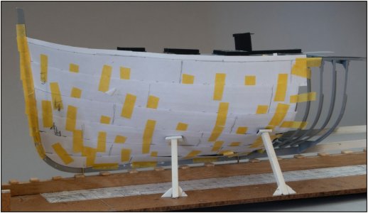
At that time I had already recognized that I had to work out the progression over the entire length.
I have now worked that out in a more arithmetic and geometrical way.
Unlike a wooden model where you can wet the hull planks and bend them into the shape of the hull and sheer, I have to cut the plates from a flat piece of Evergreen. And then start deforming them into all the curves.
Therefor I have to project all the curves of the hull in a flat plane.
For those who don't like ‘theoretical nonsense’, skip the text and perhaps the photos will make something clear.
The height of the 6 rows is not the same. I measured these using the old drawing of the main frame. I printed the frame on A3 and measured them separately:
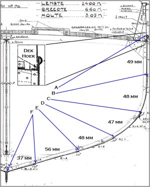
Always to the top of the next row. I will add the overlaps later when I make the plates. Now it is time to set out the lines of the 6 rows.
As can be seen in the enlarged insert, row A protrudes a bit above the outer corner profile of the waterway. The plate of the bulwark comes against it on the inside and is butted on the corner profile.
I converted the values found into percentage values in an Excel spreadsheet with some formulas:

-In yellow the individual dimensions of the rows.
-In green the values row by row added together.
-In blue the percentage length in relation to the total length.
-In grey the check whether the total is correct.
The bottom row F is smaller but bends over on the keel.
The projected length from keel to top of deck angle profile is 285 mm.
The reason for this calculations will hopefully become clear in a moment.
On the model I measured the projected length of the largest frame with a strip of mm paper. That was on frame 27:
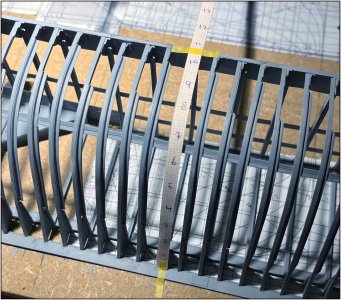
That is 10.65 cm to the top of the angle profile. Add 1.5 mm for what protrudes above. That is a total of 10.80 cm.
I entered this value in my spreadsheet where I can calculate the height of my rows based on the individual percentage blue values:

-In yellow the individual dimensions of the rows.
-In green the values row by row added together.
Which is very easy for the next step.
Under my ruler of mm paper I have placed a blank strip:

And on it I have marked the relevant values of all rows.
Started with F on the right side and worked to the left. Then the separately added values are much easier.
Up to 2 digits is in principle exaggerated. But now I know whether the line should be at the top or bottom of the mm box. 1 digit is just too coarse and you have to mark everything on the line.
With this spreadsheet I can now calculate and draw all the desired strips for different frames.
Here I have placed several and on the lines I can now check the progression with thin Evergreen:

More from below:

Now it's a matter of working through to the complex back side, removing some small irregularities and placing marking lines on the other frames. And using those lines to make the templates for the row of plates.
Regards, Peter


