OMG what can I say, it looks sensational, I'm glad you were able to repair the damage. The whole frame structure looks so fantastic, hats off, what an achievement. I really have to see it in person.
-

Win a Free Custom Engraved Brass Coin!!!
As a way to introduce our brass coins to the community, we will raffle off a free coin during the month of August. Follow link ABOVE for instructions for entering.
-

PRE-ORDER SHIPS IN SCALE TODAY!
The beloved Ships in Scale Magazine is back and charting a new course for 2026!
Discover new skills, new techniques, and new inspirations in every issue.
NOTE THAT OUR FIRST ISSUE WILL BE JAN/FEB 2026
You are using an out of date browser. It may not display this or other websites correctly.
You should upgrade or use an alternative browser.
You should upgrade or use an alternative browser.
BALDER, Vlaardingen Herring Lugger from 1912, scratch build scale 1:50 Plate-On-Frame
- Thread starter Peter Voogt
- Start date
- Watchers 65
Thanks for the compliments, Tobias.OMG what can I say, it looks sensational, I'm glad you were able to repair the damage. The whole frame structure looks so fantastic, hats off, what an achievement. I really have to see it in person.
When you are in The Netherlands you are always welcome.
Perhaps is this meeting in 2025 again nearby Frankfurt?
Regards, PeterEvery year my german friends are organizing a special event
ANNOUNCEMENT:
In May some members of the german Association "Arbeitskreis Historischer Schiffbau e.V." and of the german forum "Segelschiffsmodellbau" will meet for one day in Dieburg in the south of Frankfurt / Germany, in order to talk, show their models, look and chat.
Hi Peter,Thanks for the compliments, Tobias.
When you are in The Netherlands you are always welcome.
Perhaps is this meeting in 2025 again nearby Frankfurt?
Regards, Peter
Maybe that is a good intention for 2025, visit our German colleagues meeting in May.
Yep. And see if there are some other interesting meetings besides Amsterdam in September.Hi Peter,
Maybe that is a good intention for 2025, visit our German colleagues meeting in May.
Regards, Peter
At first for all of you my best wishes for a New Year in good health and interesting posts in your build-logs.
To apply the cement for the floor, I provided all the compartments with pieces of foam cut to size:
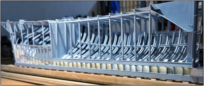
As mentioned before, with a normal hull it is a matter of filling the bottom to the desired height of the floor. With my half model it would then run out on the side.
That is why I tilted half and first filled the then flat side in steps. Once full and dry it could stand upright again:

I used again a filler that I diluted and 'greyed' with a few drops of black paint.
You can see that I have also started applying the interior of the holds. First started with the net hold. The old specifications state:
"The net hold, divided into two sections by a wooden bulkhead and accessible through two-part hatches. The panelling is smooth and made of pine. The floors are made of 1 1/2 pine with non-adjacent edges, laid on longitudinal underlays. The pumps housed in this hold are shot off with wood."
Started laying 3 floorboards with 'non-adjacent edges':
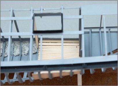
A 1.2 mm hole was drilled in the 3rd plank. The copper tube from the bottom of the pump will later go through there.
Note: On the left are the not yet completely finished parts of the floor in the barrel hold. That will be done later.
Following the floorboards, start panelling the wall:
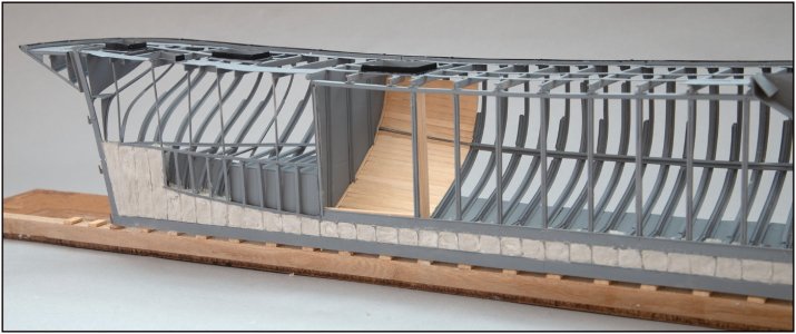
The curve of the hull distorts the course of the planks. In the direction of the bilge stringer they run parallel to it.
A skirting board along the side.
Started with the dry-fit of some test planks.
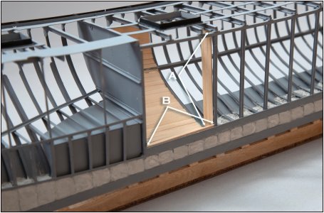
The standing planks are for the separation with the barrel hold. The two arrows 'A' point to the two U-profiles in which these planks will be placed. They should not be clamped but with a little bit of friction. Because 'clamping them just a little bit 10 times' might cause the deck beam to be pushed up.
The arrows 'B' point to the two U-profiles in which the weighing planks will be placed. The bottom one is just visible.
The planks that will be placed on top of that will have recesses:
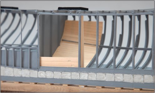
So that 'a ladder' is created to climb in and out of this hold.
A lot of fitting and measuring. The finish of the wall is not very tight like the forecastle. A net will be placed in the hold that will hide a large part from view. A bit against my habit, but sometimes: 'enough is enough'.
Regards, Peter
To apply the cement for the floor, I provided all the compartments with pieces of foam cut to size:

As mentioned before, with a normal hull it is a matter of filling the bottom to the desired height of the floor. With my half model it would then run out on the side.
That is why I tilted half and first filled the then flat side in steps. Once full and dry it could stand upright again:

I used again a filler that I diluted and 'greyed' with a few drops of black paint.
You can see that I have also started applying the interior of the holds. First started with the net hold. The old specifications state:
"The net hold, divided into two sections by a wooden bulkhead and accessible through two-part hatches. The panelling is smooth and made of pine. The floors are made of 1 1/2 pine with non-adjacent edges, laid on longitudinal underlays. The pumps housed in this hold are shot off with wood."
Started laying 3 floorboards with 'non-adjacent edges':

A 1.2 mm hole was drilled in the 3rd plank. The copper tube from the bottom of the pump will later go through there.
Note: On the left are the not yet completely finished parts of the floor in the barrel hold. That will be done later.
Following the floorboards, start panelling the wall:

The curve of the hull distorts the course of the planks. In the direction of the bilge stringer they run parallel to it.
A skirting board along the side.
Started with the dry-fit of some test planks.

The standing planks are for the separation with the barrel hold. The two arrows 'A' point to the two U-profiles in which these planks will be placed. They should not be clamped but with a little bit of friction. Because 'clamping them just a little bit 10 times' might cause the deck beam to be pushed up.
The arrows 'B' point to the two U-profiles in which the weighing planks will be placed. The bottom one is just visible.
The planks that will be placed on top of that will have recesses:

So that 'a ladder' is created to climb in and out of this hold.
A lot of fitting and measuring. The finish of the wall is not very tight like the forecastle. A net will be placed in the hold that will hide a large part from view. A bit against my habit, but sometimes: 'enough is enough'.
Regards, Peter
I love the interplay of the various materials.
Me to, Paul. The 'cold' steel and the 'warm' wood is a nice combination.I love the interplay of the various materials.
Regards, Peter
- Joined
- Oct 23, 2018
- Messages
- 886
- Points
- 403

Really wonderful, Peter. The concrete could be much smoother. You cut the hull in both parts. So you cut also the concrete.
Last edited:
Thanks, Christian. But about the smoothness I disagree. It's not a cut, it's a half-build. The top of the floor is also not evenly flat. It’s a working vessel.Really wonderful, Peter. The concrete could be much smoother. You cut the hull in both parts. So you cut also the concrete.
And …… no concrete ……. as written in post #664: “The ship is properly cemented between the frames …..with the best cosson cement and sharp river sand “
But it’s my AL-FI.
Regards, Peter
Last edited:
A happy and healthy New Year to you too, Peter. As Paul already mentioned, I also like the interplay of the different materials. Absolutely brilliant.
A happy and healthy New Year to you too, Peter. As Paul already mentioned, I also like the interplay of the different materials. Absolutely brilliant.
Thanks,Tobias and Stephan. In the combination of ‘Cold’ steel and ‘Warm’ wood I forgot the ‘Hard’ cement.A late happy New year. I agree with Paul. It is fascinating seeing all these different materials. I say it already before and keep saying it, a wonderful build.
Regards, Peter
Some side information:
What is nice and is mentioned in the Vlaardingen restoration book: During the inspection of the hold at the shipyard at the start of the 2nd restoration, a real cannon appeared to be lying in it. In the past, it was installed as extra ballast! Just before it went into the old iron container, an interested party showed up. The cannon has been moved to Groningen in the North of the Netherlands where it has been given a place at the museum 'de Wachter' in Zuidlaren. The cannon was probably fished up in the late 60s near Texel in the De Scheer gully.
Regards, Peter
Last edited:
The decision not to completely cover the hull with plating was the right one:
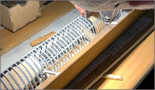
I could only tilt the planks in both U-profiles with tweezers between the frames. Each plank to size and the right curve. On the top side that of the deck and on the bottom side of the frame.
This is the result after almost 4 hours of cutting, sanding etc.:
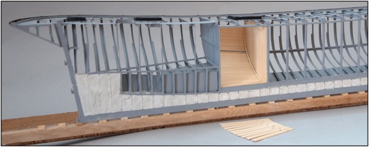
Also the skirting board, but that is partly against the side of the bottom U-profile. To mill a facet edge in that skirting board of 1.1 x 0.6 mm ......... , a challenge .......
 The fishing net will be placed over it anyway .....
On this side you can see that everything is nicely standing in the U-profile:
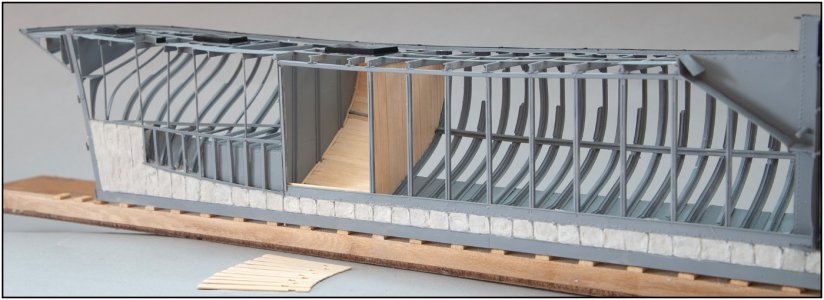
The 10 weighing planks in the lengthwise direction as a division between the two net holds:
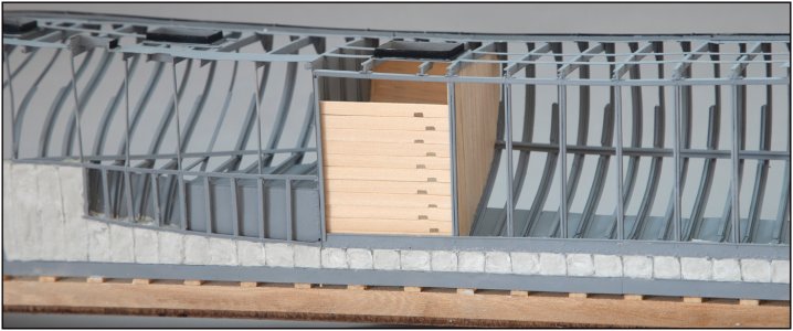
With the recesses for the 'ladder'.
Both halves still fit neatly together:

The port side section already becomes a sturdy whole thanks to both panelled compartments and the ballast over the entire length.
Regards, Peter

I could only tilt the planks in both U-profiles with tweezers between the frames. Each plank to size and the right curve. On the top side that of the deck and on the bottom side of the frame.
This is the result after almost 4 hours of cutting, sanding etc.:

Also the skirting board, but that is partly against the side of the bottom U-profile. To mill a facet edge in that skirting board of 1.1 x 0.6 mm .........
On this side you can see that everything is nicely standing in the U-profile:

The 10 weighing planks in the lengthwise direction as a division between the two net holds:

With the recesses for the 'ladder'.
Both halves still fit neatly together:

The port side section already becomes a sturdy whole thanks to both panelled compartments and the ballast over the entire length.
Regards, Peter
Oh Peter, what a distinguished art of work... Thanks for Sharing!
Thanks, Chris. For your visit, likes and new kind of complimentOh Peter, what a distinguished art of work... Thanks for Sharing!
Regards, Peter
In my enthusiasm I had let the mooring planks continue to the watertight bulkhead. In the middle, however, there is one of the two bilge pumps with panelling.
Started working on the pump.
The Amsterdam Scheepvaartmuseum had just digitalized a number of old drawings. I was given access to them to use. Also of the pumps nicely detailed with measurements accurate to the mm.
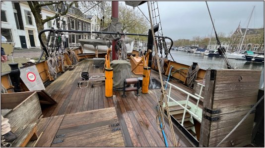
This is how they are on the Balder:
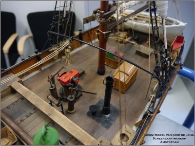
And on the model by Sybe de Jong that he made before the first restoration could start:
With this as a result:
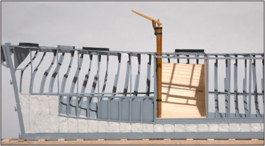
A slightly distorted image because the bulwark still has to be added.
I made the pump house from 5 mm beech round timber. At the top it is 4.6 mm and tapers towards the bottom to 3.6 mm. I made the pump rod and suction rod from 2 mm beech round timber. The brackets from strips of brass plate.
Striking to me in this photo: I already mentioned that the planks of the cladding on the inside of the hull have a strange course when viewed from different angles. At the bottom they connect to the straight floorboards, but towards the top they 'shift' parallel to the bilge gauge.
The shadows of the deck profiles and stringer plates running lengthwise run parallel to the planks in this image.
Not strange in itself because that was also visible in one of the photos of the curved bilge gauge, but seen diagonally from above it is still parallel between stringer plates for the deck hatches. A fascinating play of lines.
Back to the pump:
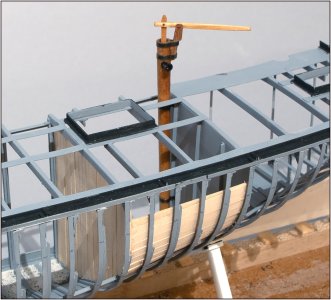
This is attached to the bulkhead with 2 brackets. And yes, the pump rod and suction rod are functional.
From another angle:
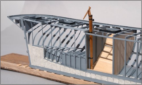
And the unforgivable macro:
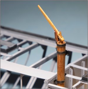
The pins are temporary. They will be replaced by brass ones. I want to be able to remove the fragile parts when I start working around it.
The next step is the cladding of the bilge pump.
Regards, Peter
Started working on the pump.
The Amsterdam Scheepvaartmuseum had just digitalized a number of old drawings. I was given access to them to use. Also of the pumps nicely detailed with measurements accurate to the mm.
This is how they are on the Balder:

And on the model by Sybe de Jong that he made before the first restoration could start:

With this as a result:

A slightly distorted image because the bulwark still has to be added.
I made the pump house from 5 mm beech round timber. At the top it is 4.6 mm and tapers towards the bottom to 3.6 mm. I made the pump rod and suction rod from 2 mm beech round timber. The brackets from strips of brass plate.
Striking to me in this photo: I already mentioned that the planks of the cladding on the inside of the hull have a strange course when viewed from different angles. At the bottom they connect to the straight floorboards, but towards the top they 'shift' parallel to the bilge gauge.
The shadows of the deck profiles and stringer plates running lengthwise run parallel to the planks in this image.
Not strange in itself because that was also visible in one of the photos of the curved bilge gauge, but seen diagonally from above it is still parallel between stringer plates for the deck hatches. A fascinating play of lines.
Back to the pump:

This is attached to the bulkhead with 2 brackets. And yes, the pump rod and suction rod are functional.
From another angle:

And the unforgivable macro:

The pins are temporary. They will be replaced by brass ones. I want to be able to remove the fragile parts when I start working around it.
The next step is the cladding of the bilge pump.
Regards, Peter
Last edited:
Thanks, Johan. Nice new description.Modeling extravaganza, that's what this is...
Regards, Peter
Fine work on the pump, Peter. The detailed work stands up to the macro images handsomely.


