- Joined
- Sep 3, 2021
- Messages
- 5,198
- Points
- 738

Always striving for perfection.For me ……. It’s almost ……
 |
As a way to introduce our brass coins to the community, we will raffle off a free coin during the month of August. Follow link ABOVE for instructions for entering. |
 |
 |
The beloved Ships in Scale Magazine is back and charting a new course for 2026! Discover new skills, new techniques, and new inspirations in every issue. NOTE THAT OUR FIRST ISSUE WILL BE JAN/FEB 2026 |
 |

Always striving for perfection.For me ……. It’s almost ……
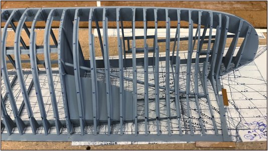


Thanks, Herman. As you can see above I could not wait till 2025 with the plates …….Awesome job and a challenging task lies ahead for 2025.
Also from my side a Merry Christmas and all the best for the next year.
……. Almost ……..Always striving for perfection.
Thanks, Paul. Yes, they have a overlap of 2,5 mm. Place for 2 of 3 rows of rivets. Length wise there will be a overlap of 1,5 mm for 1 rows.Wonderful progress, Peter. Will the plates overlap or abut one another?
How thick is the (evergreen) plating? Will you need to bevel the edges to preserve scale?Thanks, Paul. Yes, they have a overlap of 2,5 mm. Place for 2 of 3 rows of rivets. Length wise there will be a overlap of 1,5 mm for 1 rows.
Regards, Peter
It’s 0,13 mm thick. Perfect for wobbling ……. You won’t see a bevel …….How thick is the (evergreen) plating? Will you need to bevel the edges to preserve scale?
Thanks, Paul. Also for you and your beloved.Whew, that's thin stuff! Christmas blessings to you and your family, Peter. Your work is a joy to follow.
Thanks, Jim. Also for you and your beloved.Merry Christmas to you and all the Voogt family!! It is nice to make such progress towards finishing the calendar year! Enjoy as much as we are (definitely myself)




Thanks for the compliments, Mirek.Hello
It all looks beautiful Piotr. Greetings Mirek
Thanks, Paul. It is indeed a glue for plastic/styreen and acts like a solvent. Here is the link with the content: Faller 170490 The bottle has a needle point for very fine dosing.Fantastic Peter. I assume you are using glue for plastics. When I made my stove for the KF I used that and the working time was rather short and did not clean up well since it acts as a solvent. What has your experience been?
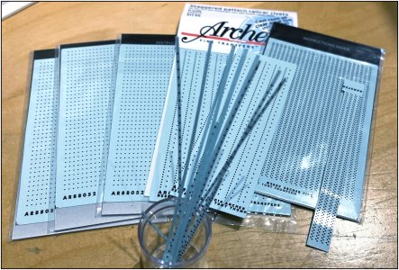
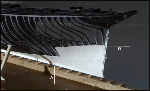
Good morning Peter. Wow at 0.13mm I would have thought the evergreen would concave in between each frame. So far very impressive. You have a gazillion rivets coming your wayAnd the second row with a picture from a lower view:
View attachment 492002
Still happy with the result .........
Back to the inside for the cement floor/ballast.
Regards, Peter
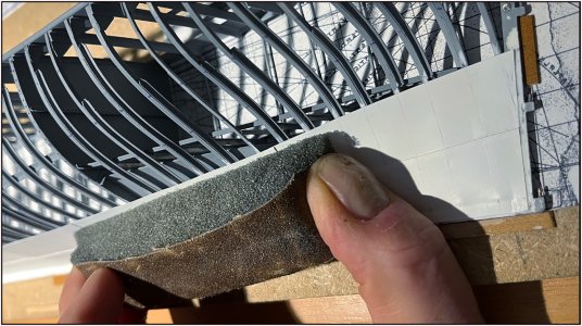
Thanks, Grant. When I apply a new plate I distribute the force over the frames with a piece of foam. The plate then retains its 'flow'. When I later slide a new plate under it from above, it distributes the force even more and the smooth line remains intact.Good morning Peter. Wow at 0.13mm I would have thought the evergreen would concave in between each frame. So far very impressive.
O yes. I don't think the current stock will be sufficient .........You have a gazillion rivets coming your way.Cheers Grant
