What you have created is a composite...there are no vertical wall additions to the gunport (you are committed now so that's a tip for the next model).Paul,
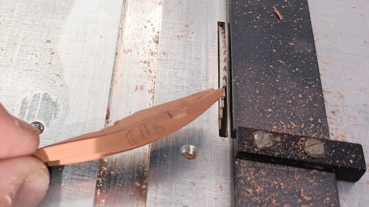
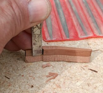
Yes, it's a challenge, once you start modifying the kits. As you can see from the first picture below, the horizontal cross members no longer fit, as my filing the header sills into the frames meant the header needed to be longer.
View attachment 430772
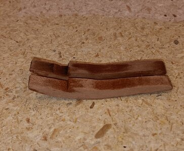
This meant I needed to make new headers/sills, just a hair longer. The good news: The upper ports all get narrower, so I can use the headers/sills from the deck below. This will keep the need to construct new pieces to a minimum. Below is a photo of the pieces dry fit in the gunport. I think the result is worth the extra work.
View attachment 430773
-

Win a Free Custom Engraved Brass Coin!!!
As a way to introduce our brass coins to the community, we will raffle off a free coin during the month of August. Follow link ABOVE for instructions for entering.
You are using an out of date browser. It may not display this or other websites correctly.
You should upgrade or use an alternative browser.
You should upgrade or use an alternative browser.
Bonhomme Richard - Pear Cross section kit (with scratch duplicate using alder) Unicorn Model
Two milestones:
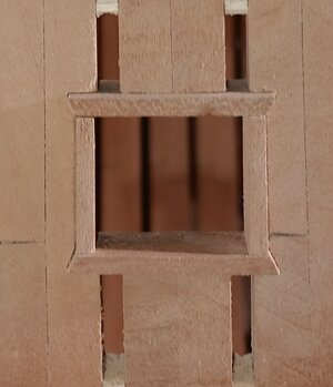
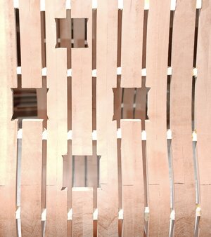
1) The composite ports, as Paul dubbed them, are carved out. As Paul pointed out, very rarely are there vertical timbers (only when frame spacing does not follow gunport spacing see photo 1). Unfortunately, I used the gunport templates in the kit which are extra wide, to allow for the vertical timbers to be included in the frame, so I was stuck with them (photo2). Photo three is the Starboard side with the frames cut out.
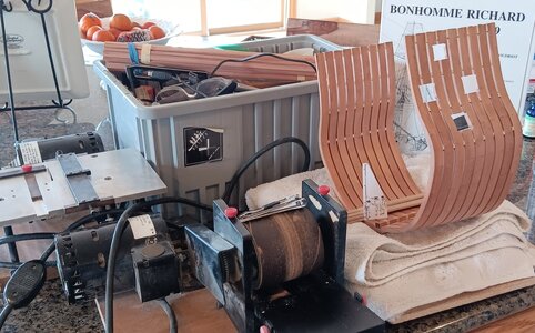
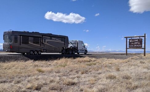
2) The Basement Shipyard is packed up and ready to move from 5,000feet to 9,000feet elevation. Photo 1 shows the Shipyard supervisors overseeing the packing of thickness mills, saws, the drydock, spare lumber and required tools for the month-long ski trip. The mobile shipyard (Photo 2) departs for Breckenridge tomorrow, after a snow delay today, which closed the I-70 mountain pass!
1) The composite ports, as Paul dubbed them, are carved out. As Paul pointed out, very rarely are there vertical timbers (only when frame spacing does not follow gunport spacing see photo 1). Unfortunately, I used the gunport templates in the kit which are extra wide, to allow for the vertical timbers to be included in the frame, so I was stuck with them (photo2). Photo three is the Starboard side with the frames cut out.


2) The Basement Shipyard is packed up and ready to move from 5,000feet to 9,000feet elevation. Photo 1 shows the Shipyard supervisors overseeing the packing of thickness mills, saws, the drydock, spare lumber and required tools for the month-long ski trip. The mobile shipyard (Photo 2) departs for Breckenridge tomorrow, after a snow delay today, which closed the I-70 mountain pass!


Last edited:
On the road again...
Stunning work Brad, i hope i can get them just as tidy as you

Very good and accurate work - have a good trip
I've determined how I will do the gunports. The kit shows them constructed with a frame that is flush with the inside and outside planking, like below:
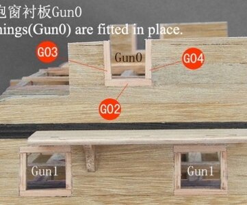
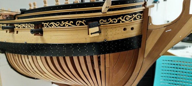
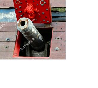
I plan to do the exterior ports like David Antscherl and Greg Herbert did on their Pegasus, with the planking going OVER the gunport frames but leaving a recess for the ports to close flush with (see 2 examples below):
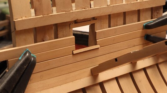
On the interior I will use the method the UWE did on his Bonhomme Richard, with planking OVER the gunport frames but the bottom of the frame standing out just a bit from the inside planking (see below):
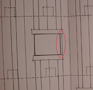
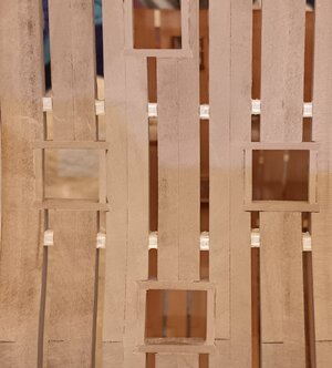
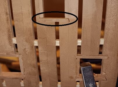
So, today I started chiseling and sanding the gunport frames to implement my plans (see below: 1st is the outside, with the gunport frames flush with the framing. The 2nd photo is the inside, where the bottom sill (circled in black) will stand out slightly from the inside planking):
I hope this method is fairly accurate and would provide a good weatherproof seal when the gunports are lowered/secured.
PS: The spring skiing in Breckenridge is awesome, so shipyard progress is somewhat slow.

I plan to do the exterior ports like David Antscherl and Greg Herbert did on their Pegasus, with the planking going OVER the gunport frames but leaving a recess for the ports to close flush with (see 2 examples below):


On the interior I will use the method the UWE did on his Bonhomme Richard, with planking OVER the gunport frames but the bottom of the frame standing out just a bit from the inside planking (see below):

So, today I started chiseling and sanding the gunport frames to implement my plans (see below: 1st is the outside, with the gunport frames flush with the framing. The 2nd photo is the inside, where the bottom sill (circled in black) will stand out slightly from the inside planking):


I hope this method is fairly accurate and would provide a good weatherproof seal when the gunports are lowered/secured.
PS: The spring skiing in Breckenridge is awesome, so shipyard progress is somewhat slow.
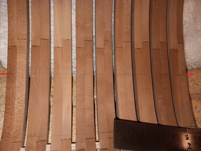
Today I marked the levels for decks 1-4.
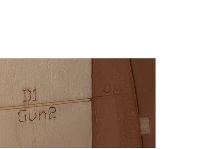
Photo 1 below shows the gauge/template provided in the kit. Use this gauge to mark the height of each deck clamp/deck support beam.
Then it is simple to align and fix a straight edge with the mark on each end. Photo 2 below:
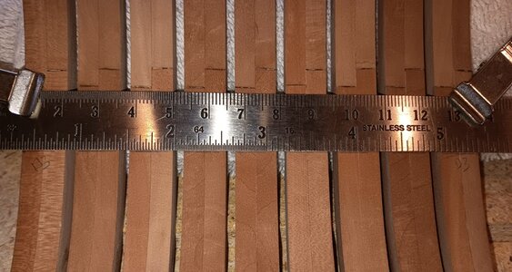
This line (red on each end) is where the deck clamps/deck support beams will be attached tomorrow.
Each deck clamp/support beam has a template which you use to determine where the beams are cut into the clamps (red lines).
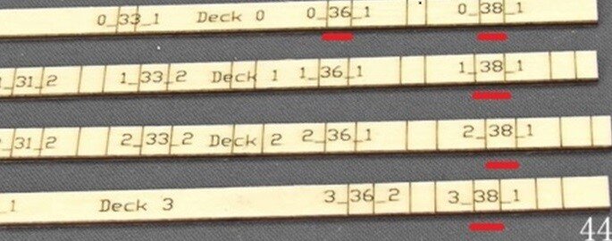
This will become clearer tomorrow, when the deck clamps are glued to the frames and the mortises for the beams are cut into the clamps.
Photo 1 below shows the gauge/template provided in the kit. Use this gauge to mark the height of each deck clamp/deck support beam.

Then it is simple to align and fix a straight edge with the mark on each end. Photo 2 below:

This line (red on each end) is where the deck clamps/deck support beams will be attached tomorrow.

Each deck clamp/support beam has a template which you use to determine where the beams are cut into the clamps (red lines).

This will become clearer tomorrow, when the deck clamps are glued to the frames and the mortises for the beams are cut into the clamps.
My second departure from the instructions sequencing. I drilled treenails on the bottom deck clamp/support beam and set it in place, trying to figure EXACTLY where to chisel the cutouts for the 3 main deck beams (see 2 photos below).

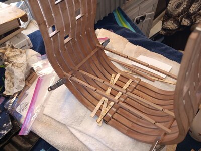
What I realized is the dozen or so cutouts that need to be chiseled into this beam are ALL dependent on the structures in the hold below it! I will wait to chisel cutouts, until all the beams that ride on this one are in place, to ensure my cutouts are perfectly aligned and not miscalculated. The template provided is a 1.5mm too long, so I don't fully trust it.
SO, I switched my efforts to the mast support structure (main mast step), the thick stuff and planking toward the keel. First photo shows how the main mast step is progressing.
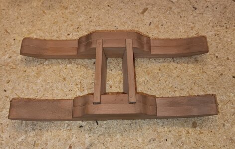
I will wait to glue it all together and add the middle rider untill the deck and thick stuff are installed so everything is flush and neat. I also experimented with making the bolt heads to be drilled into the main mast step. Here is the process I used.
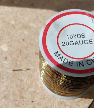
1. Cut 20 gauge wire (appox .8mm/.032in) which equates to just over a 1.5inch bolt head.
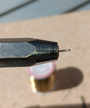
2. I placed the wire in a pin vise in my drill and made the base narrower, so it will drive into a 0.6mm hole snugly.
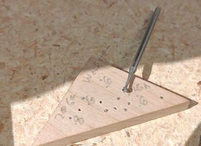
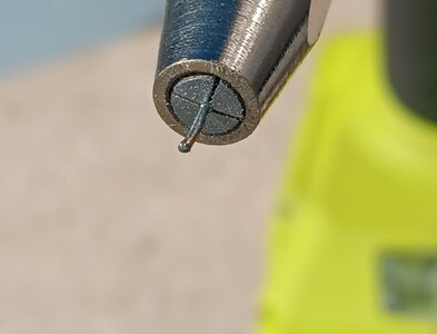
3. Then I used a small cup burnisher to round out and polish the bolt head . Below photo shows 3 bolts (in a triangle) using this method. I did not push them in completely, so they stand out slightly. There are other attempts using wood and different gauge wire, in different diameter holes, then sanded flush. The final result looks more like a rivet than a bolt but I'm happy with the bolt head simulation. Second photo shows the burnished bolt head while still in the pin vise.
Sorry for the long post. I've never made metal bolts or treenails before, so I felt I should document how a beginner made his bolts. Many thanks to Yuri for his recent tutorial on making simulating bolts with wire and nails!!!


What I realized is the dozen or so cutouts that need to be chiseled into this beam are ALL dependent on the structures in the hold below it! I will wait to chisel cutouts, until all the beams that ride on this one are in place, to ensure my cutouts are perfectly aligned and not miscalculated. The template provided is a 1.5mm too long, so I don't fully trust it.
SO, I switched my efforts to the mast support structure (main mast step), the thick stuff and planking toward the keel. First photo shows how the main mast step is progressing.

I will wait to glue it all together and add the middle rider untill the deck and thick stuff are installed so everything is flush and neat. I also experimented with making the bolt heads to be drilled into the main mast step. Here is the process I used.
1. Cut 20 gauge wire (appox .8mm/.032in) which equates to just over a 1.5inch bolt head.

2. I placed the wire in a pin vise in my drill and made the base narrower, so it will drive into a 0.6mm hole snugly.

3. Then I used a small cup burnisher to round out and polish the bolt head . Below photo shows 3 bolts (in a triangle) using this method. I did not push them in completely, so they stand out slightly. There are other attempts using wood and different gauge wire, in different diameter holes, then sanded flush. The final result looks more like a rivet than a bolt but I'm happy with the bolt head simulation. Second photo shows the burnished bolt head while still in the pin vise.


Sorry for the long post. I've never made metal bolts or treenails before, so I felt I should document how a beginner made his bolts. Many thanks to Yuri for his recent tutorial on making simulating bolts with wire and nails!!!
Excellent work. 
Yesterday I placed bolts on the mast step and they turned out decent. See below photo.
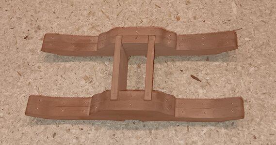
My first problem with a Mobile Shipyard: I lost a piece for the Main Rider somewhere during the shift from home to the RV (see photo below). Tonight, I will make a replacement while I'm removing char and glueing the Rider. Easy fix, as it is a mirror image of the piece on the other side.


My first problem with a Mobile Shipyard: I lost a piece for the Main Rider somewhere during the shift from home to the RV (see photo below). Tonight, I will make a replacement while I'm removing char and glueing the Rider. Easy fix, as it is a mirror image of the piece on the other side.

Very good result with these bolts 
That is a great result Brad. have fun on your ski trip
Peter,
We got close to a half meter (16 inches) of new powder over the last week, so skiing was great (photos below) but it slowed shipyard work considerably!

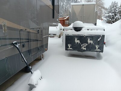
Workers have been working on small and simple tasks at the new 9,000ft altitude, while recovering from skiing and shoveling snow! I managed to saw all the thick stuff to length. I used a small template to place pin-holes with a thumbtack, to make the treenail pattern and guide the .4mm drill.
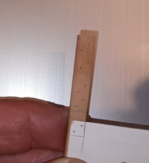
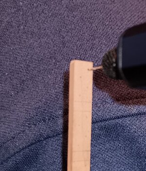
I then used a drawplate and drill to bring toothpicks down to .5mm, placed them in the holes and then sanded flush.
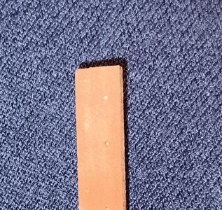
I'm pleased with the results and think the thick stuff and deck planking will look correct and to scale. The treenails should look nice and not too contrasting, when treated with a light coat of WATCO Danish wood oil.
We got close to a half meter (16 inches) of new powder over the last week, so skiing was great (photos below) but it slowed shipyard work considerably!


Workers have been working on small and simple tasks at the new 9,000ft altitude, while recovering from skiing and shoveling snow! I managed to saw all the thick stuff to length. I used a small template to place pin-holes with a thumbtack, to make the treenail pattern and guide the .4mm drill.


I then used a drawplate and drill to bring toothpicks down to .5mm, placed them in the holes and then sanded flush.

I'm pleased with the results and think the thick stuff and deck planking will look correct and to scale. The treenails should look nice and not too contrasting, when treated with a light coat of WATCO Danish wood oil.
Slowly making progress.
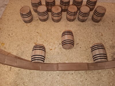
1. Completed the Main Rider and added 20gauge (.5mm) bolt heads. Plus a dozen large barrels completed, with two dozen small barrels nearing completion.
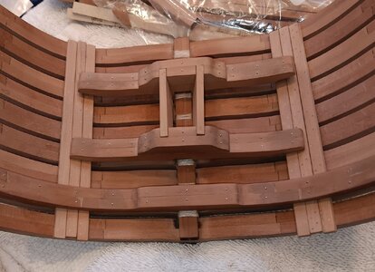
2. A quick dry fit the Main Rider, mast step and thick stuff. I slightly rounded the top edges of the thick stuff and beveled the edges to match the concavity of the hull. All look like they will fit well together.
3. Next step is glueing the keel, the thick stuff and the floor, toward the keel.
1. Completed the Main Rider and added 20gauge (.5mm) bolt heads. Plus a dozen large barrels completed, with two dozen small barrels nearing completion.

2. A quick dry fit the Main Rider, mast step and thick stuff. I slightly rounded the top edges of the thick stuff and beveled the edges to match the concavity of the hull. All look like they will fit well together.

3. Next step is glueing the keel, the thick stuff and the floor, toward the keel.
Looking great Brad! Pear sure gives a nice look, doesn't it?
Paul, The pear is superb, and it has no oil on it yet! It should really pop when the oil brings out the grain.Looking great Brad! Pear sure gives a nice look, doesn't it?
Question on Limber strakes and holes. Should I include them or not?
Last edited:
Wouldn't the Bonhomme Richard have had short Limber Boards to cover the Limber Channel, along the keel??
The Boudroit plans I have DO NOT show a Limber Channel but I believe all ships of this era had short Limber Boards (with holes to allow removal) running along the keel. These boards allowed access and cleaning (or un-clogging) of the Limber Channel.
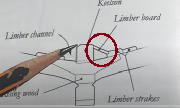
Would it be wrong to include these on this build, as neither the ZHL Kit or the Boudroit plans have Limber Boards??
The Boudroit plans I have DO NOT show a Limber Channel but I believe all ships of this era had short Limber Boards (with holes to allow removal) running along the keel. These boards allowed access and cleaning (or un-clogging) of the Limber Channel.

Would it be wrong to include these on this build, as neither the ZHL Kit or the Boudroit plans have Limber Boards??


