No, I have it though…. I am doing Bluenose ( well, after RC Glider season is over) and I am thinking I might get the Granado and do it before Enterprise and use it as a learning project. (Better instructions and jig?) transpose lessons learned (and your experience) to Enterprise?  . I like CAF Models and I think Tom’s kits are improving with each project!
-

Win a Free Custom Engraved Brass Coin!!!
As a way to introduce our brass coins to the community, we will raffle off a free coin during the month of August. Follow link ABOVE for instructions for entering.
-

PRE-ORDER SHIPS IN SCALE TODAY!
The beloved Ships in Scale Magazine is back and charting a new course for 2026!
Discover new skills, new techniques, and new inspirations in every issue.
NOTE THAT OUR FIRST ISSUE WILL BE JAN/FEB 2026
You are using an out of date browser. It may not display this or other websites correctly.
You should upgrade or use an alternative browser.
You should upgrade or use an alternative browser.
Build Log "CAF" HMS Enterprise
- Thread starter Paul132
- Start date
- Watchers 40
-
- Tags
- caf model enterprise pof
Here to help guys, but I'm just an average hack model builder.
- Joined
- Apr 20, 2020
- Messages
- 6,241
- Points
- 738

you are doing wonderful workYesterday finished the head/hawse timbers, some sanding still needed, will be beveled to fit frame 1 later, and mu usual 3 frames a day, now have completed 7-33
- Joined
- Jan 31, 2021
- Messages
- 566
- Points
- 353

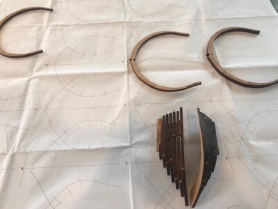
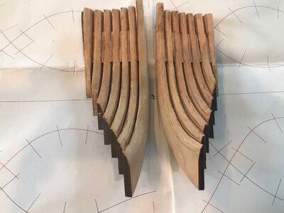
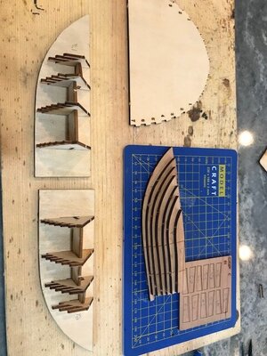
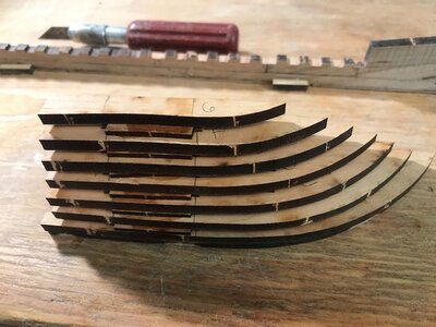
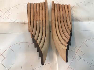
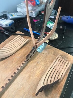
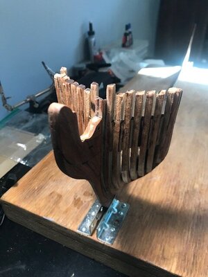
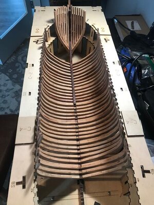
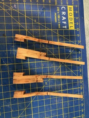
Ok, back at it the last few days, the Head/Hawse Timbers gave me a challenge, as the first time doing them. I used the supplied jigs to build the head timbers, then fitted and attached cant frame 1 to the keel/stem. Then attempted to attache the completed head timber sets on both port and starboard sides, beveling the interior to line up to Frame 1. Did not like the results of this, so removed the head timbers(they werent glued in yet, and then removed the cant frame 1(which were glued in). Then I actually attached the head timber set to the stem on both sides first, then re beveled them to fit cant frame 1 in on both sides. It was a learning experience! If anyone has a proven method on this, please share! Pictures show the completed head timbers out of the jig, Cant frame 1 installed first, then the completed bow section on the main jig, and finally all together, Bow section and Frames 8-39. Nothing has been glued in at this point nor frames exteriors beveled.


Last edited by a moderator:
- Joined
- Jan 31, 2021
- Messages
- 566
- Points
- 353

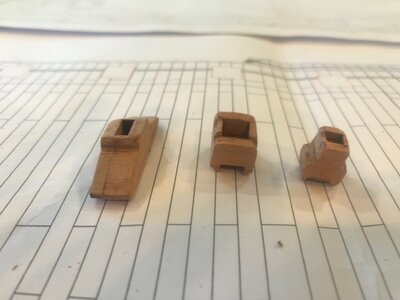
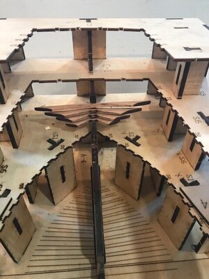
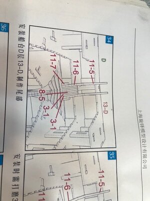
Started the Stern components yesterday, by cutting, fitting, and beveling wing transom and filling transoms, and attached them. Today I built some of the other stern components, but partially built them outside the jig, the plans show them installed in the jig. Then I installed them in the jig. Also set frames 8-16 today.
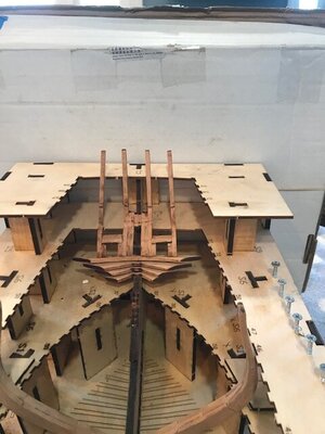


Last edited by a moderator:
Wow Paul, that’s a lot, those hawse timber’s look good - I wondered how the best way to bevel those would be, looks like you figured it unit for the rest of us. It also looks like those stern timber’s are going to be a bear also, fitting those first stern cant frames to the wing transom pieces will be a custom fit as well?
- Joined
- Jan 31, 2021
- Messages
- 566
- Points
- 353

Lou, yes the cant frames are difficult, there hard to see inside the jig and see the fit, I will fit the stern cant frames individually, beveling as needed, the hawse head timbers were more of a pain than the stern so far, if I had to do over, I would probably attach Cant frame 1 first and the fit the hawse timbers individually, rather than as a complete unit.
- Joined
- Jan 31, 2021
- Messages
- 566
- Points
- 353

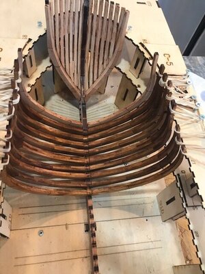
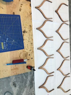
Made good progress today, finished building Aft Cant frames( still need sanding). Also, attached to the keel frames 9 thru 36, as well as 46. I am missing two pieces to finish the build up of the stern, Tom at CAF was very quick and is mailing them to me. Also, you may notice, I haven taken all the char off the interior of the frames, and stained them a mini wax golden oak, I debated this, but I tested it on some leftover wood, and it brought the grain out of the wood nicely. Also, in sanding all the frames, taking the char off, test fitting them all, and then staining them. The installation of the frames was a breeze. Have attached the keelson from the bow to past midships as well to give the frame some more solidity.
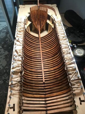
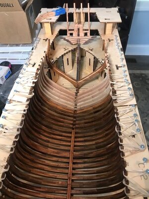


Last edited by a moderator:
Very good progress - step by step, better frame by frame you are creating a hull 
- Joined
- Jan 31, 2021
- Messages
- 566
- Points
- 353

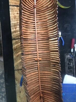
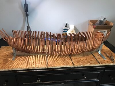
Folks, All the frames are now complete and have been attached, stern is complete as it can be(still waiting on 2 pieces from Caf). Interesting time taking it out of the jig, had to take the top layer of the jig off to get it out. Next step will be interior deck stringers to give the hull some strength, then back in the jig to begin the deck beams.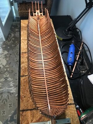
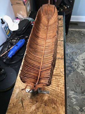


Last edited by a moderator:
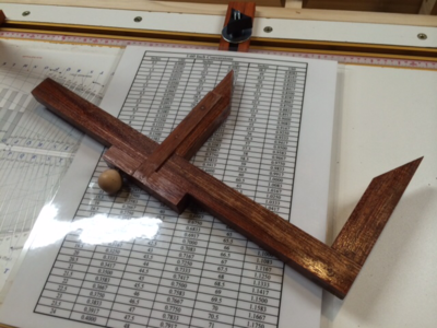
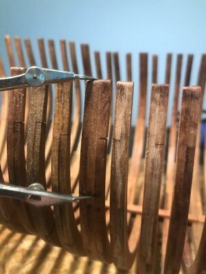
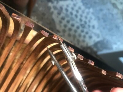
No, but other builds I have only seen measurement taken from the keel upwards for decks, gunports, etc. Here is a pic of some calipers as made per Ed Tosti’s HMS Niaid books, every thing is measured from the build board, (bottom of keel) upwards, marked on outer side of frames and transferred to the inside (when needed, deck clamps etc.)

- Joined
- Jan 31, 2021
- Messages
- 566
- Points
- 353

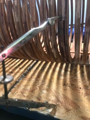
Ok, here is how I measured for the Deck Stringers, hope this works, seems accurate to the line drawing. 1. Measured from bottom of False keel to Stringer Line on Line Drawing. 2. Transfered this to the Exterior of the Hull. 3. Measured from Stringer line to top of frame. 4. Then Transferred this to interior of the frame. Will be putting it back into the jig and attaching the Mid Frame Stringer first on both sides. More to come on this one.....Hope it works out!!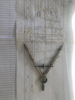


Last edited by a moderator:


