-

Win a Free Custom Engraved Brass Coin!!!
As a way to introduce our brass coins to the community, we will raffle off a free coin during the month of August. Follow link ABOVE for instructions for entering.
-

PRE-ORDER SHIPS IN SCALE TODAY!
The beloved Ships in Scale Magazine is back and charting a new course for 2026!
Discover new skills, new techniques, and new inspirations in every issue.
NOTE THAT OUR FIRST ISSUE WILL BE JAN/FEB 2026
You are using an out of date browser. It may not display this or other websites correctly.
You should upgrade or use an alternative browser.
You should upgrade or use an alternative browser.
Thank You John and I wish you the best with your build. Please start a log and I among others will follow along
I am having a short sabbatical to work on Santisima Trinidad but will resume work on Imara when weather warms up a bit
I am having a short sabbatical to work on Santisima Trinidad but will resume work on Imara when weather warms up a bit
I am back on this build after recent issues with my chest where I wanted to keep away from Epoxy etc whilst I recovered.
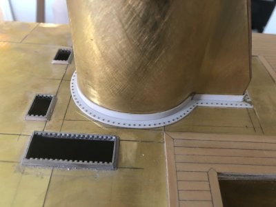
Whilst waiting for Epoxy to dry whilst plating the funnel (pictures to follow) I have done a trial of my rivet detail.
First picture shows what 3000 0.5mm brass nails from Drydock models and parts looks like.
Other pictures show what they look like installed. I am more than happy with the results. I had two big concerns, they would be too prominent and secondly they would be too sloppy in a freehand drilled 0.5mm hole. A hole is rarely the true size when the item is not fixed in a machine.
I have a plan for a Drilling guide which I will show in a later post.


Last edited:
NMBROOKI am back on this build after recent issues with my chest where I wanted to keep away from Epoxy etc whilst I recovered.
Whilst waiting for Epoxy to dry whilst plating the funnel (pictures to follow) I have done a trial of my rivet detail.
First picture shows what 3000 0.5mm brass nails from Drydock models and parts looks like.
Other pictures show what they look like installed. I am more than happy with the results. I had two big concerns, they would be too prominent and secondly they would be too sloppy in a freehand drilled 0.5mm hole. A hole is rarely the true size when the item is not fixed in a machine.
I have a plan for a Dillingers guide which I will show in a later post.
View attachment 504092View attachment 504093View attachment 504094
Great idea for rivet details. Can’t wait to see how it will look.
I have completed the initial plating of the funnel after a plethora of filling and sanding to take out the asymmetry and irregularity of the fibreglass moulding.This plating was in 0.12mm brass which enabled it to be able to rap around the curve sections.
The creases were bent using my PE folder in the last picture.
Work is now focused on preparing the funnel top to take a large white metal casting supplied in the kit
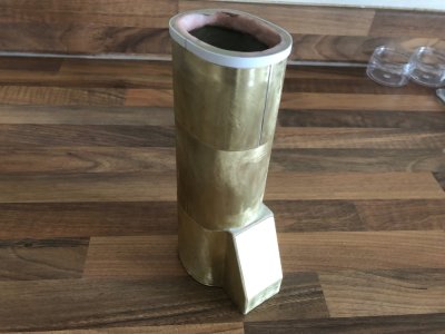
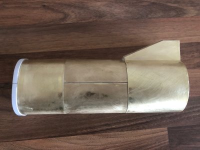


The creases were bent using my PE folder in the last picture.
Work is now focused on preparing the funnel top to take a large white metal casting supplied in the kit


The fibreglass funnel had full plating detail that was lost when I sorted the irregularities of it’s shape.Same approach as the superstructure moulding.
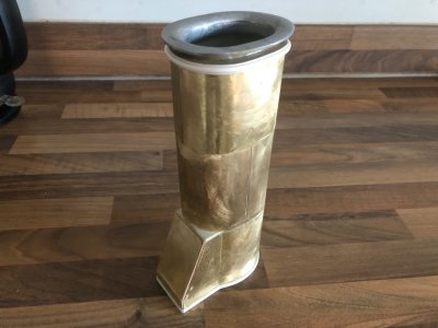
I have now fitted the supplied cast funnel top and finished the rib detail below with a plastic D moulding. There is another of these bands to add on the base of the top row of funnel plating but I will fit this later as it gets in the way of my drill guide.
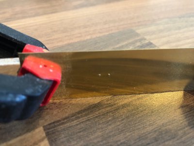
My hacksaw blade drill guide works a treat as in the second picture. Simply tape to the funnel and rest the drill tip against the vee of every other saw tooth (18 TPI blade)
The last picture shows the hull placed on the superstructure. The bottom flange of the angle has been glued and "riveted" to the top of the structure. Rivet detail will be added to the section of plastic at the base of the funnel.
The two plastic sections will be glued together but the strength will come from fibreglassing the inside of the funnel to the inside of the superstructure top.
You will notice the kit supplied grill surrounds have been fitted with the superstructure cut out to make these working vents as the prototype. Any air passage I can get into the hull is a bonus with the steam plant.


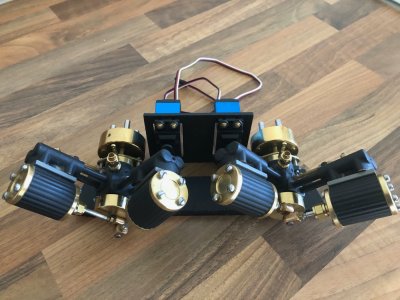
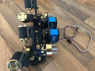
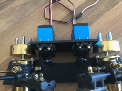
Apologies for my absence. I have been busy both at work and on this model. A lot has been done in the development of the interior layout of the steam plant and I shall post photos in a little while once I have something understandable to display.
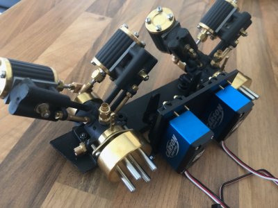
For now here are some photos of the finally painted engine assembly complete with my home-brew designed and machined engine/throttle servo mount.This complete assembly can be removed from the model as a unit for maintenance and is only held in the model by two bolts.
I have gone through the learning curve of bending and silver soldering steam pipework. I have made the exhaust sections to run up to the Steam condenser so far. As I side note I drilled and tapped the exhaust ports out in the engine blocks the same as I did on the inlet to take 1/4 x 40 fittings as they seemed a tad small. no pictures just yet as the pipe "lagging" is currently waiting on the last coat of white enamel
One kick in the teeth, somehow I have lost one of the screws that holds the gland to one of the cylinders,don't ask me how but hey ho. Replacement screw on order from PM Research in Brooklyn NY via the UK distributor.The thread size I know from others is a spurious American size so not simply a case of ordering one locally.I should imagine the screw will only be a few cents so the postage will probably ten fold.
I am taking the engine assembly with me to the model shop tomorrow to find suitable linkages for the servos to throttles. I have seen something suitable online but no sizes are given, believe they are for model aircraft undercarriages so much easier to say "what have you got that fits this?"
The servos BTW are Carson waterproof metal gear CS9s with 9kg of pull.They will get wet and do have to work against the throttle compression sealing washer, hence my choice.


Last edited:
Thanks Bluebeard but I have to say yes and no.Whilst the steam engines themselves and servos are are fairly new to the market, the engine design is probably fifty years old. Everything other than these has been designed and machined by my fair hand and there aint nothing high tech about me


No Cad, drawn on paper with the help of a calculator and machined with no CNC just Vernier calipers as these were made prior to acquiring my new mill with DRO. I can't even claim the prop shaft dog drive principle as mine, it has been around for decades before I was born.
However, I do feel very happy though that everything has worked together, lots to deal with as space was tight height wise and width wise plus the servos only miss the flywheels by a few mm as designed to ensure the servo arms do not clash at their full travel (about 5mm between them, like I say, tight). Contra rotating props mean the servo arms will point towards each other going in one direction, yet to be determined when I steam them. I have servo reverse on my transmitter so that is not an issue.
I do know know that the engine room will resemble the under bonnet of an old V12 jaguar XJS, I know now that with everything fitted and plumbed it is going to be very busy in there. I have, unlike the Jaguar, come up with a design that allows ease of pond side maintenance with everything removable with ease using no special tools. I know others mount everything on a tray and the whole lot comes out in one go. Because the outermost cylinders go under the decks, I would have had to have removable sections to allow the engines to pass through the opening. I wished to avoid this as it would compromise the integrity of a very heavy model and more deck planking to get to line through on the joints
A brief explanation on plumbing production.
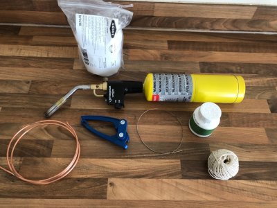
Here is a list of what I use;
Copper tube, 5/32" in this case supplied in roll format
Silver solder supplied in rod
Water soluble flux powder
Tube bending pliers
Fire bricks
Rothenberger professional blowtorch
Citric acid in powder form
String
Not shown in the first photo
Plumbing fittings
Cyano glue
White enamel paint
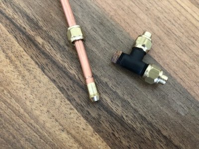
The second picture shows how the pipework joins to the fittings, prior to soldering the nipple.
A brass coned nipple is silver soldered onto the end of each pipe after first sliding on the brass compression nut.
It is basically a case of straightening the copper tube, soldering nipples on each end then pickling
The citric acid powder is added to water in a pan on the stove and boiled up.
The plumbing parts are placed in this solution and boiled for around ten minutes. This removes all traces of oxide, heat discolouration and flux.The parts are then rinsed in water
Too weak a solution and it takes longer, too strong and you have a sticky film left on the parts that comes off with scrubbing in hot soapy water.
Best part is the citric acid is freely available on Amazon and is food grade. Yes I use a normal saucepan for the job !
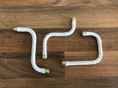
After cleaning, the parts a "lagged" with string wrapped around their length with the help of Cyano to hold the string in place. I then apply further thin CA to the strung to soak in and firm it up.
Finally the pipe lagging has three coats of white enamel paint applied.
This lagging helps prevent burns from hot pipework when working on the model whilst being operated. It also stiffens the pipework up. Just need to take care that the compression nut can still rotate after doing all this. I found a light twist on the nut with a spanner freed off the paint holding onto it.
The last picture shows the three completed sections that run from the exhaust ports to the steam condenser.


During the planning of the installation I have made some changes and additions to the original plan as follows;
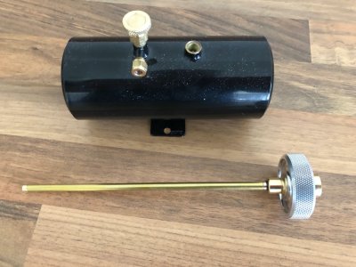
Refillable gas tank. The original idea of using a camping cylinder in the model wouldn't work as it simply was too large especially when you include the valve and flex hose. This tank is filled from a camping refill using the bottle adapter also shown in the picture
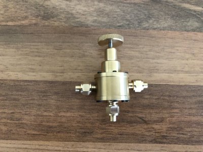
Gas attenuation valve.This fits in the gas line to the burner and takes a feed from the boiler.The feed from the boiler controls the valve at a preset pressure via the knurled knob.Basically when the boiler reaches a set pressure the valve reduces the gas to a pilot setting to conserve both gas and steam. Mine will be set at 50PSI. The boiler safety valve is set at 60PSI should not be needed under normal running. This should result in longer running times between boiler refills
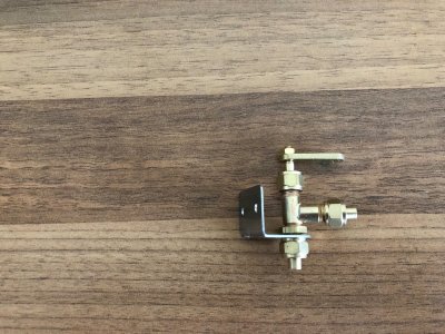
Gas shut off valve. This simply does what it says and is installed immediately next to the gas tank. Should the model suffer a breakdown in the middle of the pond, the gas can be shut of using RC via a servo connected to the arm on the valve. Without this, the boiler could boil dry whilst waiting for the model to be recovered
Refillable gas tank. The original idea of using a camping cylinder in the model wouldn't work as it simply was too large especially when you include the valve and flex hose. This tank is filled from a camping refill using the bottle adapter also shown in the picture

Gas attenuation valve.This fits in the gas line to the burner and takes a feed from the boiler.The feed from the boiler controls the valve at a preset pressure via the knurled knob.Basically when the boiler reaches a set pressure the valve reduces the gas to a pilot setting to conserve both gas and steam. Mine will be set at 50PSI. The boiler safety valve is set at 60PSI should not be needed under normal running. This should result in longer running times between boiler refills

Gas shut off valve. This simply does what it says and is installed immediately next to the gas tank. Should the model suffer a breakdown in the middle of the pond, the gas can be shut of using RC via a servo connected to the arm on the valve. Without this, the boiler could boil dry whilst waiting for the model to be recovered

Last edited:
Update as to where the hull is now up to
The aft end has been boxed in to provide support to take a 1.5mm ply subdeck as yet unfitted.This includes a mounting for the rudder servo which is just plonked in position for now.Excuse the masking on the stainless propshaft oiler tubes. This is staying put for now as more painting to do once the ply deck is fitted. There are two longitudinal beams to fit outside of these tubes to form part of a combing structure for the engine house which will be removable to access receiver,rudder servo and radio battery.
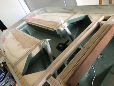
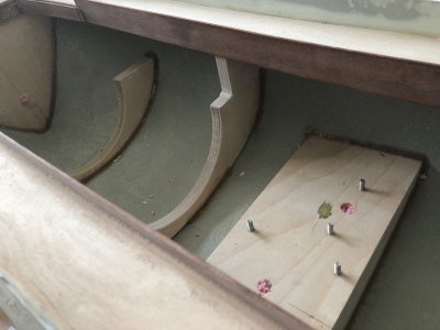
Supports have been added inside the hull for the boiler and a platform with Stainless mounting studs for the condenser and gas tank. The pink in the pictures is 4 hour fire rated expanding foam. This has been injected in all enclosed compartments to seal everything and offer addition strength. The holes will be cleaned out and filled with wood filler.
The bow section has been boxed in forward of the boiler which meant installing the s. These are supplied now as a 3D print in the kit and are very detailed. These are bonded and sealed inside the hull as they only sit an inch or so above the waterline.
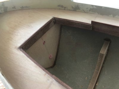
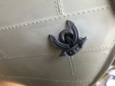
One massive modification I have made is a section of the deck at the bow is now attached to the superstructure. This is solidly built as the mast will fit into this. This change gives me unhindered access to the boiler twin burners and visibility of both water level sight glass and boiler pressure gauge.It also means the boiler can easily be removed straight upwards as there is insufficient room to slide backwards had it hooked under the deck.Added bonus is that I can install lighting, battery and switch all independently in the superstructure as I was adamant there would be no electrical wires linking hull to superstructure. Also having the mast attached to the superstructure makes the model much easier to transport.
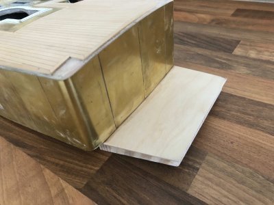
This takes me up to where the model currently stands progress wise. Next on the agenda is to fit threaded studs to hold boiler retaining bands then instal the boiler engines and gas tank to enable me to make up all the rest of the plumbing. I can then take everything apart and finish painting the interior.
I chose the shade of green as it was a nice "period" colour that suits the vessel and will go well with the rest of the steam installation.The hatch combings I plan on varnishing the mahogany. The paint is actually Wickes "garden paint" and fairly inexpensive for 2.5 litres. I did a trial on a piece of plywood, applying three coats, allowing them to dry for 24 hours then pouring boiling water over it straight from the kettle. It withstood this without any issues and given it has a five year guarantee for use outside, I figured it was fit for purpose
The aft end has been boxed in to provide support to take a 1.5mm ply subdeck as yet unfitted.This includes a mounting for the rudder servo which is just plonked in position for now.Excuse the masking on the stainless propshaft oiler tubes. This is staying put for now as more painting to do once the ply deck is fitted. There are two longitudinal beams to fit outside of these tubes to form part of a combing structure for the engine house which will be removable to access receiver,rudder servo and radio battery.

Supports have been added inside the hull for the boiler and a platform with Stainless mounting studs for the condenser and gas tank. The pink in the pictures is 4 hour fire rated expanding foam. This has been injected in all enclosed compartments to seal everything and offer addition strength. The holes will be cleaned out and filled with wood filler.

The bow section has been boxed in forward of the boiler which meant installing the
 s. These are supplied now as a 3D print in the kit and are very detailed. These are bonded and sealed inside the hull as they only sit an inch or so above the waterline.

One massive modification I have made is a section of the deck at the bow is now attached to the superstructure. This is solidly built as the mast will fit into this. This change gives me unhindered access to the boiler twin burners and visibility of both water level sight glass and boiler pressure gauge.It also means the boiler can easily be removed straight upwards as there is insufficient room to slide backwards had it hooked under the deck.Added bonus is that I can install lighting, battery and switch all independently in the superstructure as I was adamant there would be no electrical wires linking hull to superstructure. Also having the mast attached to the superstructure makes the model much easier to transport.


This takes me up to where the model currently stands progress wise. Next on the agenda is to fit threaded studs to hold boiler retaining bands then instal the boiler engines and gas tank to enable me to make up all the rest of the plumbing. I can then take everything apart and finish painting the interior.
I chose the shade of green as it was a nice "period" colour that suits the vessel and will go well with the rest of the steam installation.The hatch combings I plan on varnishing the mahogany. The paint is actually Wickes "garden paint" and fairly inexpensive for 2.5 litres. I did a trial on a piece of plywood, applying three coats, allowing them to dry for 24 hours then pouring boiling water over it straight from the kettle. It withstood this without any issues and given it has a five year guarantee for use outside, I figured it was fit for purpose
Last edited:
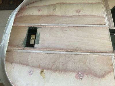
I don't normally do much modelling during the week as I currently work 11.5 hour nightshifts but I have set myself a goal.
On Sunday 25th May ( 5 weeks yesterday) it is Kirklees model Boat club live `steam open day. Anyone can come along with their Steam powered models and sail on the lake provided you have a current boiler certificate ( which I have )
My Goal is to get the model running and sail that day. Yes it will be far from finished but the next stage will be to strip the internals and focus just on the scale modelling aspect of the build before final installation of the steam plant.
So the next couple of jobs crossed of the LONG list
Rudder linkages intstalled and tested. I used carbon pushrods as these are more rigid given the distance between rudder and servo
Final section of subdeck fitted. This was prepainted underneath before fitting. The whole aft subdeck will be subject to further sanding to refine the transition between camber and sheer.
On Sunday 25th May ( 5 weeks yesterday) it is Kirklees model Boat club live `steam open day. Anyone can come along with their Steam powered models and sail on the lake provided you have a current boiler certificate ( which I have )
My Goal is to get the model running and sail that day. Yes it will be far from finished but the next stage will be to strip the internals and focus just on the scale modelling aspect of the build before final installation of the steam plant.
So the next couple of jobs crossed of the LONG list
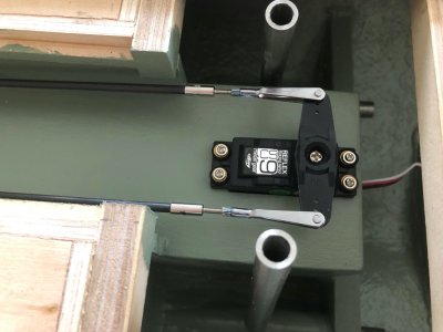
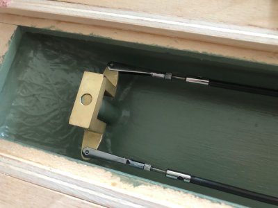
Rudder linkages intstalled and tested. I used carbon pushrods as these are more rigid given the distance between rudder and servo


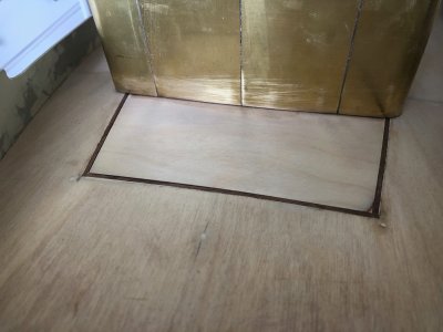
Final section of subdeck fitted. This was prepainted underneath before fitting. The whole aft subdeck will be subject to further sanding to refine the transition between camber and sheer.

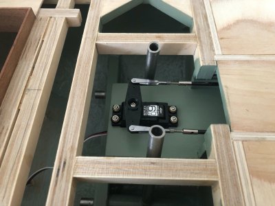
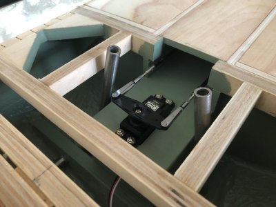
A small update from today's work but I thought I would post it as the aft deck will be on the next updates.
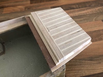
Two birch ply beams have been fitted which act as support for the deck combing that takes the removable aft section of superstructure.Angling the bandsaw table means the tops follow the deck camber eliminating the need to fair the top face of these and ensuring the side faces are perpendicular to the waterline.
Two birch ply beams have been fitted which act as support for the deck combing that takes the removable aft section of superstructure.Angling the bandsaw table means the tops follow the deck camber eliminating the need to fair the top face of these and ensuring the side faces are perpendicular to the waterline.


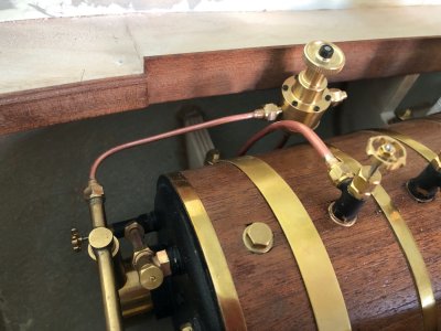
Plumbing,plumbing and more plumbing........
With everything placed in the hull I am in the middle of making and trial fitting all the pipework.
The first picture shows the gas Attenuator valve in position with gas feed to the burners and pressure feed from the boiler using an additional steam valve as a takeoff.
The displacement lubricators are connected to the steam feed pipe via Globe valves. These enable me to shut either engine down and run the other to help with diagnostics. This assembly is temporarily chocked up to enable me to make the steam feed manifolds for each engine at the same time ensuring the gas tank can be removed for refilling and I have enough space for the gas shut off servo.
As a side note the exposed brass of the condenser will be clad in Mahogany as the boiler
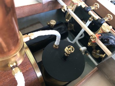
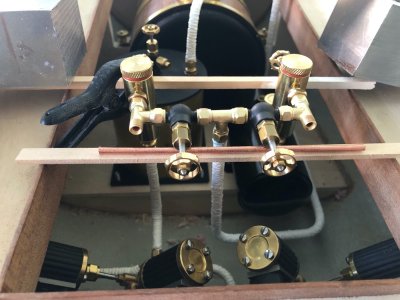
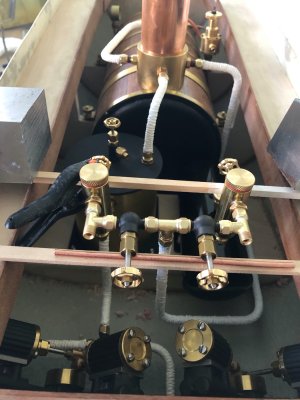


Hi Nigel,Plumbing,plumbing and more plumbing........
With everything placed in the hull I am in the middle of making and trial fitting all the pipework.
The first picture shows the gas Attenuator valve in position with gas feed to the burners and pressure feed from the boiler using an additional steam valve as a takeoff.
The displacement lubricators are connected to the steam feed pipe via Globe valves. These enable me to shut either engine down and run the other to help with diagnostics. This assembly is temporarily chocked up to enable me to make the steam feed manifolds for each engine at the same time ensuring the gas tank can be removed for refilling and I have enough space for the gas shut off servo.
As a side note the exposed brass of the condenser will be clad in Mahogany as the boiler
View attachment 517352View attachment 517353View attachment 517354View attachment 517355
Coming along very nicely.
Do you intend to rely on the pipe work to support the displacement lubricators and globe valves or is there going to be some sort of support for that assembly?
Cheers,
Stephen.


