-

Win a Free Custom Engraved Brass Coin!!!
As a way to introduce our brass coins to the community, we will raffle off a free coin during the month of August. Follow link ABOVE for instructions for entering.
-

PRE-ORDER SHIPS IN SCALE TODAY!
The beloved Ships in Scale Magazine is back and charting a new course for 2026!
Discover new skills, new techniques, and new inspirations in every issue.
NOTE THAT OUR FIRST ISSUE WILL BE JAN/FEB 2026
You are using an out of date browser. It may not display this or other websites correctly.
You should upgrade or use an alternative browser.
You should upgrade or use an alternative browser.
I next glued in place the gun deck framing flooring and waterways as I did the previous decks.
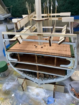
I am fitting the gun deck side walls in place. To fit well it requires enlarging 2 of the notches on each side. Of course that caused the sidewalls to break and I had to glue the sections again. ATTENTION: I edited this in after discovering a serious mistake I made. You can see it in the posting down below. The 2 gun deck walls are NOT symmetrical it was only mentioned in passing in the instructions that there are a port and starboard deck wall. The port and starboard are not labeled as such and you have to figure it out. One way is to take the Exterior gun and spar walls and set them up as they would be on the ship. There are 2 gun ports and a lower section when the walkway to the ship fits. This lower section goes to the stern of the ship. Once you temporarily fit these into place you can see which wall will align with the gun ports on which side. The gun ports are not placed equally along this inner wall. Mark the port and starboard walls.
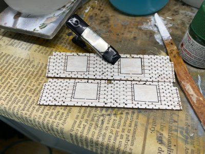
While enlarging the notches I realized that the exterior and interior wall here have to line up for the gun ports to align. The exterior walls are not to go on until later. I have to investigate how to make sure they align before I put these walls in. I intend to do as much as I can before the walls go in.

I am fitting the gun deck side walls in place. To fit well it requires enlarging 2 of the notches on each side. Of course that caused the sidewalls to break and I had to glue the sections again. ATTENTION: I edited this in after discovering a serious mistake I made. You can see it in the posting down below. The 2 gun deck walls are NOT symmetrical it was only mentioned in passing in the instructions that there are a port and starboard deck wall. The port and starboard are not labeled as such and you have to figure it out. One way is to take the Exterior gun and spar walls and set them up as they would be on the ship. There are 2 gun ports and a lower section when the walkway to the ship fits. This lower section goes to the stern of the ship. Once you temporarily fit these into place you can see which wall will align with the gun ports on which side. The gun ports are not placed equally along this inner wall. Mark the port and starboard walls.

While enlarging the notches I realized that the exterior and interior wall here have to line up for the gun ports to align. The exterior walls are not to go on until later. I have to investigate how to make sure they align before I put these walls in. I intend to do as much as I can before the walls go in.
Last edited:
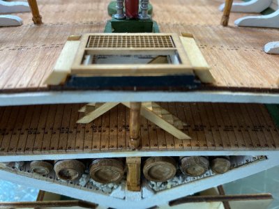
I decided next to put the bilge pump bodies into place. This makes sense as the are more centrally located and will be more easily manipulated. As you can see the pump bodies have to be shortened a bit to fit flush with the deck.

You then had to slide and glue the collar under the pump body before securing it into place which was a bit tricky.

Each pump body had to be individually fitted, filing down the end for a proper fit. If i were to do it again I would not place the hatchway in place until these pump bodies were properly fitted.

Finally everything is looking shipshape!
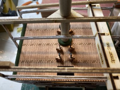

You then had to slide and glue the collar under the pump body before securing it into place which was a bit tricky.

Each pump body had to be individually fitted, filing down the end for a proper fit. If i were to do it again I would not place the hatchway in place until these pump bodies were properly fitted.

Finally everything is looking shipshape!

They would have you make eyebolts for the sidewalls, but my kit included eyebolts. While I was blackening them with brass black. I noticed that the holes in the side walls were not in the same position as in the instruction book. The are along side and slightly diagonal from the bottom sided of the gunports in the book.

on the actual piece they are well below and far away from the gunports. I am not sure how this error can be made with a laser cut piece, but I will see if others had this problem. The same problem was noted by Tom Culb in his build log. He elected to go along with the pre drilled holes and used double eyebolts in a few of them. I will do the same thing.

on the actual piece they are well below and far away from the gunports. I am not sure how this error can be made with a laser cut piece, but I will see if others had this problem. The same problem was noted by Tom Culb in his build log. He elected to go along with the pre drilled holes and used double eyebolts in a few of them. I will do the same thing.
Last edited:
Gok
Good morning Rob. I really like those pumps. Very cool indeed. Cheers GrantI decided next to put the bilge pump bodies into place. This makes sense as the are more centrally located and will be more easily manipulated. As you can see the pump bodies have to be shortened a bit to fit flush with the deck.
View attachment 505095
You then had to slide and glue the collar under the pump body before securing it into place which was a bit tricky.
View attachment 505096
Each pump body had to be individually fitted, filing down the end for a proper fit. If i were to do it again I would not place the hatchway in place until these pump bodies were properly fitted.
View attachment 505097
Finally everything is looking shipshape!
View attachment 505098
Thank you Grant for all your kind words and encouragement!Gok
Good morning Rob. I really like those pumps. Very cool indeed. Cheers Grant
Rob
Eyebolts were next put into place on the sidewalls. Instead of making double eyebolts as suggested by the manual, I just bent eyebolts at an angle and inserted 2 where I needed double eyebolts. The eyebolts were secured with CA cement.
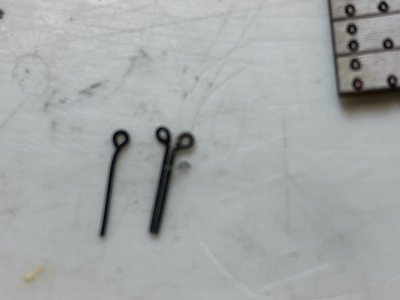
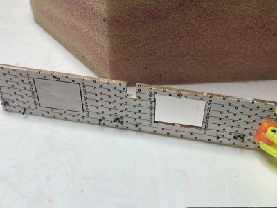
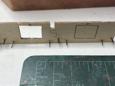
Once the CA dried I put a dab of wood glue, allowed that to dry and then snipped the ends of the eyebolts off.


Once the CA dried I put a dab of wood glue, allowed that to dry and then snipped the ends of the eyebolts off.
The metal parts of the pump mechanisms were filed to get rid of any flash, which was minimal.

The metal was then primed and painted flat black using enamel paints. The dual pumps were assembled first and fit into place nicely. everything was attached with CA.
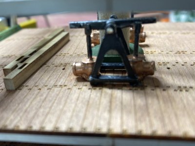
The pump handle extesions were painted brown on the handle part to resemble wood and glued one at a time in place. Care was taken to make sure the handles did not interfere with the bitt posts as stated in the manual.


The metal was then primed and painted flat black using enamel paints. The dual pumps were assembled first and fit into place nicely. everything was attached with CA.

The pump handle extesions were painted brown on the handle part to resemble wood and glued one at a time in place. Care was taken to make sure the handles did not interfere with the bitt posts as stated in the manual.

The quadruple pumps were next take care of. Other builders have noted a problem with the hatchway fairing interfering with the pump supports, but I found no problem. The support fitted right nxt to the fairing with no real interference.
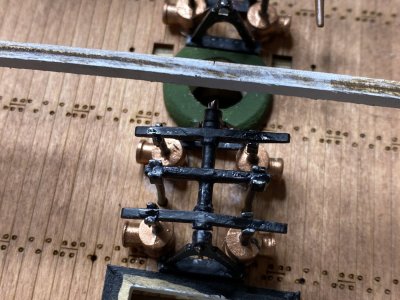
Once the CA set the pump handles were glued into place.
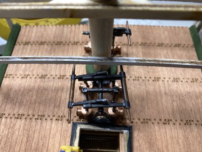
The hatchway fairing was then glued into place.
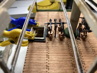

Once the CA set the pump handles were glued into place.

The hatchway fairing was then glued into place.

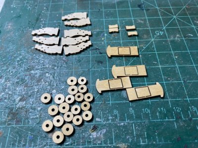
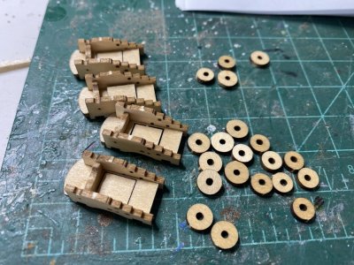
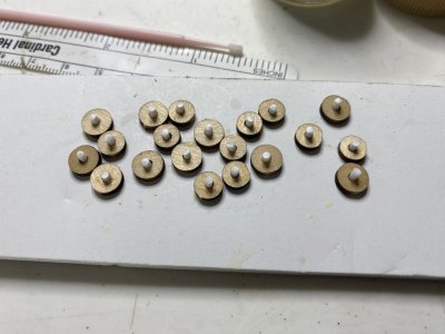
The manual would have you take 3/32nd square stock and have you carve round axles on each end. I decided to use the method Tom Culb did and glue short pieced of round rod into the wheels to simulate axles and then glue the wheels onto the stock. I cut 3/32nd square stock into one half inch lengths and then glued them into place.
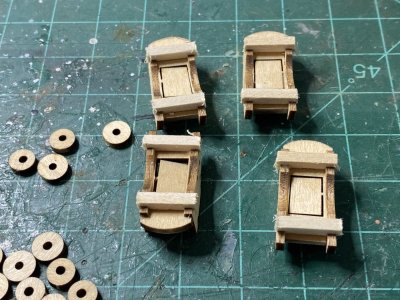
I then used some 1/16th inch round plastic rod I had to simulate the axle.
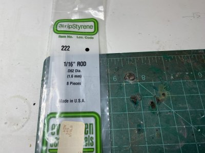

I then used some 1/16th inch round plastic rod I had to simulate the axle.

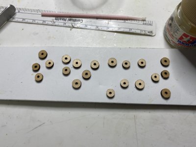
I secured the wheels to a piece of foam board by using a piece of tape folded upon itself to make double sided tape. The wheels and axles were then painted with flat black paint.

Although I could not find in the instructions which wheels go in the front, my research on the internet indicate that the small wheels go to the rear of the cannon.

Although I could not find in the instructions which wheels go in the front, my research on the internet indicate that the small wheels go to the rear of the cannon.
When I was cleaning the flash off the cannons in preparation to paint them, I noted that one of the cannons was missing the cascable, the rear part where the breeching line is wrapped around. After thinking about it for a while, I thought I could repurpose one of the brass belaying pins that are included in the kit.
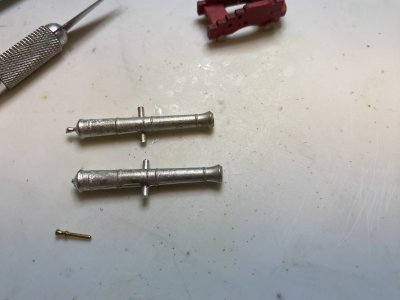
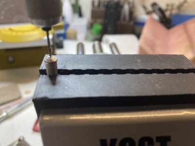
I sanded the end of the cannon a little bit flat so it would be easier to drill. I mounted the cannon in my vise and using a small drill bit with a pin vise, I was easily able to drill a hole into the cannon.
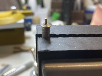
I cut the end of the belaying pin down a bit and glued it into place using CA glue.
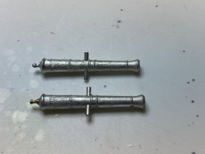
I think that the repaired cannon looks better than the originals.

I sanded the end of the cannon a little bit flat so it would be easier to drill. I mounted the cannon in my vise and using a small drill bit with a pin vise, I was easily able to drill a hole into the cannon.

I cut the end of the belaying pin down a bit and glued it into place using CA glue.

I think that the repaired cannon looks better than the originals.

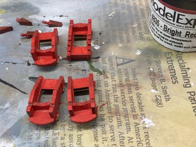
The wheels were attached to the carriages.
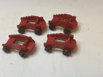
The cannons were primed to get them ready for black enamel paint.

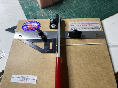
To make the trammels to hold the cannon trummels in place, I took the supplied brass strip and annealed it by heating it until it was red hot. It was then cut into small strips. I took a 1/16th inch rod and taped it down on the cutting board. The annealed brass rod was then pressed into place on the rod using the jaws of a small needle nose pliers.
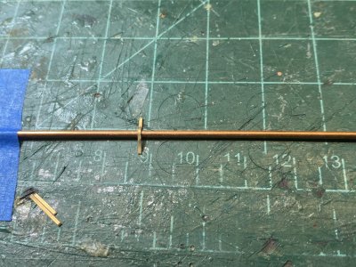

The cannons were primed to get them ready for black enamel paint.

To make the trammels to hold the cannon trummels in place, I took the supplied brass strip and annealed it by heating it until it was red hot. It was then cut into small strips. I took a 1/16th inch rod and taped it down on the cutting board. The annealed brass rod was then pressed into place on the rod using the jaws of a small needle nose pliers.

I set some cannons up on the model deck to see how they look. In my opinion, the trunnions on the cannons are to short by about a 32nd of an inch. They just barely fir across and once I have them positioned properly I will glue them into place.
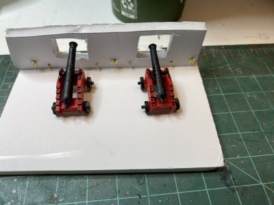
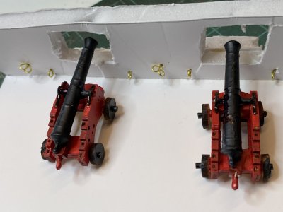
Above you can see the cannons set in place with the quoins set into place that control their elevation.
As suggested by the instructions I soaked the breeching lines (and I guess other line in the future) and stretched them out using 2 "helping hands" until they dried. This definitely make the line easier to handle and took out the "kinks" set in by folding then line when shipped. I think that the line that is included for the breeching line is too thick. Tom Culb in his building log used a smaller diameter line and I may do the same. Looking at photos of the modern Constitution cannons, their line is smaller. However the original ropes may have been much thicker. An online discussion of breaching line says "It was roughly 1/3 the diameter of the shot, and was long enough (3 times the length of the cannon bore) to allow the cannon to move about a foot or two inboard of the bulwark to give the gun crew room to swab and load the cannon." If it was 1/3 the diameter of the shot, the lines supplied are too thick.

Last edited:
Using the thinner line I seized some of what are described as "large" hooks onto the line. I am really quite new to doing this and luckily you tube has a few people demonstrating how they seize lines. I found the method used by J Brent to be very helpful.
"Helping hands" are a real necessity (at least for me) when seizing the lines. The hook is held in a clamp after I threaded the line through it. It smaler thread used for seizing has one end taped to the clamp while the other is formed into a loop and then wound around the breeching line.
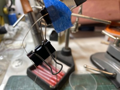
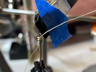
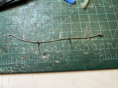
After the line was seized, I put a drop of CA to prevent the threads from unraveling. Two eyebolts which are to be inserted into the gun carrage are placed before the other end of the line has its hook seized into place.
"Helping hands" are a real necessity (at least for me) when seizing the lines. The hook is held in a clamp after I threaded the line through it. It smaler thread used for seizing has one end taped to the clamp while the other is formed into a loop and then wound around the breeching line.


After the line was seized, I put a drop of CA to prevent the threads from unraveling. Two eyebolts which are to be inserted into the gun carrage are placed before the other end of the line has its hook seized into place.

The middle of the breeching line was then wrapped around the cascabel of the cannon and affixed with a small drop of CA.
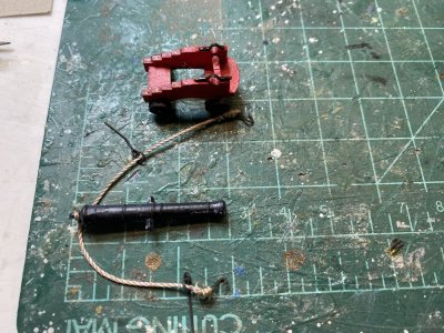
The cannon was then seated on its carriage, The quoims were glued into place to place the barrels at the elevation I wanted. The eyebolts stems trimmed and using CA fixed into the carriage.
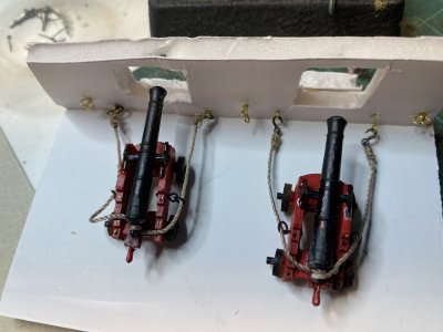

The cannon was then seated on its carriage, The quoims were glued into place to place the barrels at the elevation I wanted. The eyebolts stems trimmed and using CA fixed into the carriage.

Last edited:


